
The evolution of gear manufacturing has been profoundly shaped by the pursuit of efficiency and precision in producing complex gear forms, with spiral bevel and hypoid gears standing as prime examples. These gears represent one of the most intricate forms of power transmission, and their production has historically been synonymous with complexity—both in the multi-step machining processes and in the elaborate, mechanically adjusted machines required to execute them. My work focuses on harnessing the power of modern Computer Numerical Control (CNC) to revolutionize this domain. The transition from traditional mechanical gear generators to fully CNC gear milling machines, often termed “Free-Form” or “Gleason-Type” machines, marks a paradigm shift. While these advanced machines dramatically simplify mechanical architecture by replacing complex gear trains and cams with multi-axis servo drives, the underlying intellectual challenge of controlling the tool-workpiece relationship to generate the correct tooth geometry remains. Therefore, the true potential of a fully CNC gear milling machine is unlocked only by a sophisticated, dedicated software system that translates design intent into flawless machine motion. This article details the development of such an integrated CNC gear milling software system, from fundamental principles and architectural design to practical implementation and validation through cutting tests.
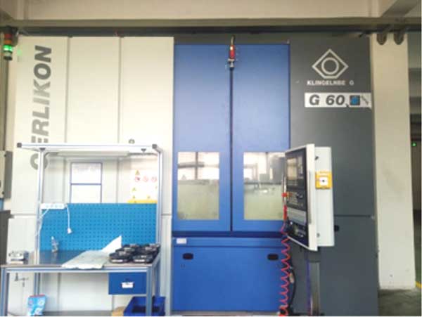
Principles of Gear Milling on Fully CNC Machines
The core objective in bevel gear milling is to generate the desired tooth flank geometry through the enveloping motion of a rotating cutter (the tool) relative to the gear blank (the workpiece). In a traditional mechanical machine, this relative motion is achieved through a fixed kinematic chain involving a cradle (simulating the generating gear), various slides for positioning, and a mechanical differential for roll. A fully CNC gear milling machine deconstructs this fixed chain into independent, programmable axes. The machine’s capability is defined by its ability to coordinate these axes to replicate—and extend beyond—any relative motion possible on a mechanical machine.
The typical configuration involves five or six axes of motion. The fundamental gear milling action, which is the generating roll between the imaginary crown gear (cradle) and the workpiece, is achieved through synchronized motion of the cutter spindle’s virtual rotation (simulated by linear axes) and the workpiece rotation. The key lies in mapping traditional mechanical adjustments to CNC axes:
| Traditional Mechanical Adjustment | CNC Axis Implementation | Description |
|---|---|---|
| Cradle Roll (C) | Synchronized Linear Axis (X) and Rotary Cutter (B) | The cradle’s rotary motion is emulated by coordinated linear movement of the cutter head and its own rotation. |
| Workpiece Rotation (A) | Rotary Axis (A) | Directly controlled by a rotary table axis. |
| Sliding Base (Horizontal & Vertical) | Linear Axes (Y, Z) | Positions the workpiece center relative to the cutter center. |
| Machine Root Angle | Rotary Axis (Ctilt) | Tilts the workpiece axis to set the root angle. |
| Cutter Tilt & Swivel (for Modified Roll) | Integrated into Cutter Spindle Axes (e.g., B-axis tilt) | Used for advanced methods like Modified Roll (Tilt) or Helical Motion. |
This mapping allows the CNC machine to execute all conventional gear milling methods—Single Side, Duplex, Spread Blade, Formate, and Helixform—by precisely controlling the toolpath. More importantly, it enables free-form gear milling for advanced flank corrections that are difficult or impossible to achieve on mechanical machines.
The mathematical foundation is the spatial kinematics of the machine tool. The position of the cutter blade tip relative to the workpiece coordinate system is defined by a chain of homogeneous transformations. For a given machine configuration, the cutter location (CL) point \(\mathbf{P}_{c}\) in cutter coordinates is transformed to the workpiece coordinate system \(\mathbf{P}_{w}\):
$$
\mathbf{P}_{w} = \mathbf{T}_{A}(\theta_A) \cdot \mathbf{T}_{C_{tilt}}(\gamma) \cdot \mathbf{T}_{Y}(y) \cdot \mathbf{T}_{Z}(z) \cdot \mathbf{T}_{X}(x) \cdot \mathbf{T}_{B}(\theta_B) \cdot \mathbf{P}_{c}
$$
Where:
- \(\mathbf{T}_{A}, \mathbf{T}_{B}, \mathbf{T}_{C_{tilt}}\) are rotation matrices for the A-axis (workpiece), B-axis (cutter spindle), and C_tilt-axis (root angle).
- \(\mathbf{T}_{X}, \mathbf{T}_{Y}, \mathbf{T}_{Z}\) are translation matrices for the linear axes.
- \(\theta_A, \theta_B, x, y, z, \gamma\) are the instantaneous axis positions.
The gear milling process requires that the tool envelope this calculated surface. For generating (rolling) motions, \(\theta_A\) and the combination of \(x\) and \(\theta_B\) that emulate the cradle roll \(\phi_c\) are linked by the gear ratio \(R_{G}\):
$$
\theta_A = R_{G} \cdot \phi_c + \theta_{A0}
$$
The software’s core algorithmic library must solve the inverse kinematics: given a desired relative motion between tool and workpiece (defined by the “machine settings” from gear design), calculate the time-dependent setpoints for all CNC axes \([x(t), y(t), z(t), \theta_A(t), \theta_B(t), \gamma]\). This forms the basis for the NC code generation.
Software System Architecture Design
The developed gear milling software is designed as an embedded application within the Siemens SINUMERIK 840D sl CNC system. Its architecture is modular, ensuring clarity, maintainability, and robustness for the complex task of gear milling. The system is partitioned into four primary functional modules and a central motion control algorithm library, interconnected through dynamic data exchange (DDE) with the CNC’s system variables.
- File Management Module: This module handles all gear data input/output. Its primary function is to import, parse, and manage the “setting sheet” or “calculation sheet”—a data file containing all geometric parameters (gear data), machine adjustment settings (e.g., basic machine settings, tilt coefficients), and process parameters (feed rates, speeds, cycle definitions). It provides interfaces for viewing, editing, validating, and saving these parameters, forming the essential dataset for any gear milling job.
- Status Monitoring Module: This is the primary human-machine interface (HMI) during gear milling operation. It provides real-time visualization of:
- Axis positions (actual, commanded, distance-to-go).
- Virtual cradle angle and its relationship to the workpiece.
- Cutting depth progress and remaining stock.
- Process information: current tooth number, cycle time, active feed rates, spindle loads.
This module gives the operator full situational awareness of the ongoing gear milling process.
- Auxiliary Functions Module: Gear milling involves many setup and ancillary operations beyond the main cutting cycle. This module groups these functions:
- Tool Setting: Procedures for referencing the cutter diameter and length.
- Workpiece Setup: Functions for aligning the blank, setting the work origin.
- Indexing/Parting: Controlling the A-axis for tooth indexing and for parting cuts.
- Stock Division: A critical function for finish gear milling. It allows the operator to manually jog to a specific tooth, take a trial cut, measure the remaining stock, and then automatically calculate and apply a Z-axis offset to evenly distribute the finishing allowance across all teeth.
- Return to Roll Center: Moves all axes to the defined start position for the generating roll.
- Alarm and Help Module: This module ensures operational safety and ease of use. It performs real-time checks on input parameters for physical feasibility and machine limits. It provides context-sensitive help, guiding the operator through correct procedures for loading data, setting up, and executing the gear milling cycles.
- Motion Control Algorithm Library: This is the computational heart of the software. It contains the proprietary algorithms that:
- Transform traditional machine settings into the kinematic model of the specific CNC gear milling machine.
- Calculate the toolpath (cutter location data) for roughing (spread blade, duplex) and finishing (single-side, modified roll) cycles.
- Perform the post-processing to convert toolpath data into Siemens-specific NC code, heavily utilizing R-parameters for flexibility.
- Implement the real-time cutting depth calculation and compensation logic.
The modules interact seamlessly. For instance, the File Management Module loads a setting sheet; the Algorithm Library processes it; the Status Module displays the resulting machine state; and the Auxiliary Functions Module uses outputs from the Algorithm Library (like offset values) to execute setup tasks. All communication with the CNC for axis control is managed through synchronized reading and writing of system R-parameters and global variables.
Software Development and Implementation
HMI Development with Siemens Tools
The operator interface was developed using Siemens’ HMI development tool, ProTool/Pro. The goal was to create an application that integrates natively with the SINUMERIK Operate environment. The development followed a structured process:
- Environment Setup: The project was built upon standard Siemens HMI class templates and forms to ensure compatibility with the base system. Custom templates were added for the specific gear milling application to manage window sequences, global variables, and initialization files.
- Framework Construction: A detailed framework map was created, defining all HMI screens (windows) and their interconnection via softkeys. This map was translated into configuration files (`*.seq` for sequence control, `*.ilk` for window lists) that dictate the application’s flow. For example, pressing the “Stock Division” softkey in the Auxiliary Functions window triggers a specific sequence that calls the calculation routine and then switches to a manual jog screen.
- Language DLL Creation: A dynamic link library (DLL) was compiled to manage the multilingual text strings for all softkeys and messages, ensuring the software could be deployed in different regions.
- Screen Design and Logic Programming: Each HMI screen was graphically designed. The underlying logic for each screen element (buttons, data fields, displays) was programmed in C. Crucially, the callback functions for each softkey were implemented in the main program module, linking operator input to core software functions like starting a calculation or triggering an axis movement.
- Integration with SINUMERIK Operate: The compiled executable and its configuration files were installed on the CNC’s HMI PC. The SINUMERIK startup configuration was modified to add a new softkey labeled “Gear Milling” on the main overview page. Pressing this key loads and launches the custom gear milling software, making it an integral part of the machine’s control interface.
NC Code Generation and R-Parameter Programming Logic
A cornerstone of this software is the automatic generation of efficient and flexible NC code. Instead of generating a monolithic, fixed program for each gear, the system uses a parametric programming approach centered on Siemens R-parameters. A single, master NC program is used for all gear milling operations on a given machine. The specific behavior of this program is controlled by the values written into R-parameters by the HMI application via DDE.
The core logic is driven by a master R-parameter, e.g., `R100`, which acts as a function selector. The HMI software sets `R100` to a specific value to command different phases of the gear milling process. The NC program structure is a large case selection based on `R100`:
“`
;— Main Program Gears_Milling.MPF —
N10 DEF INT FUNC_SELECT
N20 FUNC_SELECT = R100 ; Read function code from HMI
N30
N40 CASE FUNC_SELECT OF
N50 GOTO 100 LABEL “RETURN_TO_CENTER” ; R100 = 1
N60 GOTO 200 LABEL “STOCK_TEST_CUT” ; R100 = 2
N70 GOTO 300 LABEL “FINAL_MILLING” ; R100 = 3
N80 GOTO 400 LABEL “INDEX_TOOTH” ; R100 = 4
N90 DEFAULT GOTO 999
N100 ENDCASE
N110
N200 ; — Subprogram for Final Gear Milling Cycle —
N210 R101 = TOTAL_TEETH ; Number of teeth from HMI
N220 R102 = 1 ; Current tooth counter
N230
N240 WHILE R102 <= R101
N250 ; — Calculate dynamic offsets for this tooth (calls subprogram) —
N260 L1000
N270 ; — Execute the generating roll move for one tooth —
N280 G01 X… Y… Z… A… B… F…
N290 ; — Retract, index, approach —
N300 G00 Z…
N310 A = A + 360 / R101 ; Index to next tooth
N320 R102 = R102 + 1 ; Increment counter
N330 ENDWHILE
N340 M30
“`
The workflow for finishing a pinion illustrates this interaction:
- The operator imports the finish gear milling setting sheet via the File Management screen and generates the NC data. The algorithm library calculates all necessary motion coefficients and stores them in a set of R-parameters (e.g., `R50-R90` for roll coefficients, `R20` for basic radial distance).
- After workpiece setup, the operator presses “Return to Roll Center” in the Auxiliary Functions screen. The HMI sets `R100=1` and starts the NC program. The machine moves all axes to the defined starting position for the generating roll.
- The operator performs manual tool touch-off on a specific tooth. Then, pressing “Stock Division” sets `R100=2`. The HMI records the current Z-axis position, calculates the required offset to achieve uniform stock, stores it in `R25` (Z-offset), and starts the NC program. The machine executes a single cut on the test tooth.
- If the test cut is satisfactory, the operator moves to the Status screen and initiates the “Start Milling” command. The HMI sets `R100=3`, `R101` (tooth count), and `R102=1` (reset counter), then starts the NC program. The machine automatically executes the complete finishing cycle for all teeth. During this cycle, the HMI locks out conflicting auxiliary functions to prevent interference.
The algorithm for generating the toolpath within the motion control library is iterative. For a given instant of cradle roll angle \(\phi_c(i)\), the corresponding workpiece rotation \(\theta_A(i)\) is calculated. Simultaneously, the required linear axis positions \(X(i), Z(i)\) to position the cutter tip correctly for that phase of the roll are computed based on the machine kinematics and the modified roll (tilt) polynomial if applicable. This series of discrete points \([X(i), Z(i), \theta_A(i)]\) is then smoothed and formatted into NC blocks with appropriate feed commands, creating the continuous, synchronized motion essential for precise gear milling.
Gear Milling Experiments and Validation
To validate the correctness and practicality of the developed software system, it was deployed on a commercial six-axis, five-axis联动 fully CNC hypoid gear milling machine, the YK7380. A pair of truck rear axle hypoid gears was selected as the test case. The basic parameters of the gear set are listed below:
| Parameter | Pinion | Gear |
|---|---|---|
| Number of Teeth | 10 | 41 |
| Module (mm) | 9.25 | – |
| Shaft Angle (deg) | 90 | |
| Offset (mm) | 30 | |
| Mean Spiral Angle (deg) | 50.0 (LH) | 32.5 (RH) |
| Face Width (mm) | 46 | 41 |
| Hand of Spiral | Left | Right |
| Pressure Angle (deg) | 20 | 20 |
The entire gear milling process—both roughing and finishing—was conducted on the YK7380 machine using the developed software. Multiple established gear milling methods were employed to test the software’s versatility:
- Gear (Ring Gear): Both roughing and finishing were performed using the conventional Duplex gear milling method. The software successfully calculated the toolpaths for the inside and outside blade groups and generated the NC code for the coordinated motions.
- Pinion:
- Roughing was done using Conventional (no-modified-roll) Single-Side gear milling to open the tooth slots.
- Finishing was tested with two advanced methods:
- Helixform (Fixed Setting) gear milling: A method utilizing cutter tilt and swivel to locally modify the contact pattern.
- Modified Roll (Roll-Tilt) gear milling: A method where the relationship between cradle roll and workpiece rotation is altered by a polynomial function during the roll to correct flank topography.
For each method, the software imported the respective setting sheet data (containing tilt coefficients, roll modification polynomials, etc.). The motion control algorithm processed these settings, performed the kinematic transformations for the YK7380’s specific axis configuration, and generated the corresponding NC programs. The gear milling cycles executed smoothly. The critical finish gear milling operations produced tooth flanks with the required geometry and surface finish. The ability of the software to correctly implement both conventional and advanced roll-modified gear milling cycles was conclusively demonstrated. The final machined gear set confirmed that the software-enabled CNC machine could replicate the capabilities of traditional machines and execute complex, digitally-defined toolpaths with high precision.
Conclusion
The development of a dedicated CNC software system is not merely an addition but a fundamental prerequisite for realizing the capabilities of a fully CNC bevel and hypoid gear milling machine. This project successfully designed and implemented such a system, integrating seamlessly with the Siemens SINUMERIK 840D sl platform. The software’s architecture, with its clear separation between user interface modules and a powerful motion control algorithm library, provides a robust framework for managing the entire gear milling process—from data import and setup to real-time monitoring and execution of complex cutting cycles. The use of R-parameter-based NC programming creates unparalleled flexibility, allowing a single program to handle diverse operations through dynamic variable control.
The core achievement lies in the algorithm library that accurately translates traditional gear design settings into the multi-axis coordinated motions of a modern CNC machine. This translation enables not just the emulation of all classical gear milling methods but also opens the door to advanced free-form flank machining. The practical validation through comprehensive gear milling experiments on a production-grade machine, employing multiple methods including Modified Roll gear milling, confirmed the software’s correctness, reliability, and industrial practicality. This software system effectively bridges the gap between the sophisticated geometry of bevel gears and the flexible, programmable nature of modern CNC machine tools, unlocking new levels of efficiency and capability in gear manufacturing.