
The pursuit of precision, efficiency, and reliability in modern manufacturing is inextricably linked to the advancement of machine tool technology. Among these, CNC gear milling machines represent a critical category, essential for producing the complex, high-strength gears required in aerospace, automotive, and heavy machinery. The performance of a gear milling machine directly dictates the quality of the machined components, influencing their noise, vibration, durability, and power transmission efficiency. A pivotal component in the structural chain of such machines, particularly in vertical configurations, is the ram. The ram acts as the primary carrier for the cutting tool spindle, extending into the workspace to perform the material removal process. Consequently, its structural characteristics are paramount. It must possess exceptional static stiffness to resist deflection under heavy cutting loads, thereby ensuring dimensional accuracy and surface finish. Simultaneously, its dynamic stiffness, reflected in its natural frequencies and mode shapes, must be sufficiently high to avoid resonant vibrations that can chatter, degrade tool life, and compromise surface integrity. Furthermore, as a moving component responsible for the Z-axis feed motion, its mass significantly impacts the machine’s acceleration capabilities, servo response, and overall energy consumption. Therefore, the design challenge for a modern ram is to achieve an optimal balance between maximum stiffness, superior dynamic performance, and minimum mass—a quintessential lightweight design problem. This article delves into a comprehensive methodology for the structural optimization of a ram for a high-performance CNC gear milling machine, employing integrated finite element analysis, multi-objective topology optimization, and meta-structure design principles.
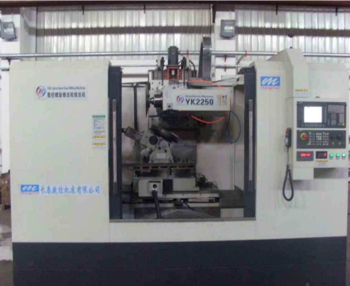
The foundation of any rigorous structural optimization is a high-fidelity computational model. The process begins with the creation of a detailed finite element (FE) model of the entire gear milling machine assembly. To ensure computational efficiency without sacrificing critical accuracy, intelligent model simplification is necessary. Small, non-structural features like chamfers, fillets, and minor bolt holes that have negligible impact on global stiffness can be suppressed. The model is then discretized using a mix of tetrahedral and hexahedral elements, with a refined mesh applied to areas of high stress concentration or geometric complexity, such as the ram itself, the guide rail interfaces, and the spindle housing. Coarser meshes can be used for larger, more uniform volumes like the machine bed and column. A representative model, highlighting the ram’s position, is shown below.
Material properties are assigned accurately: major cast iron components like the bed and column are typically modeled with an elastic modulus of 120 GPa, a Poisson’s ratio of 0.27, and a density of 7200 kg/m³. Steel components for guide rails, ballscrews, and the spindle system use an elastic modulus of 200 GPa, a Poisson’s ratio of 0.3, and a density of 7850 kg/m³. Defining realistic connections between components is crucial. Fixed joints, such as those between the bed and column, are modeled using bonded contact, simulating a welded or integrally cast connection. Moving joints, like the linear guideways connecting the ram to the column, are modeled with frictionless or rough contact, allowing only the intended degrees of freedom while transmitting forces and moments.
The final step in model preparation is applying boundary conditions and operational loads. The machine bed is fully constrained at its mounting points to the foundation. For static analysis, gravitational acceleration is applied to the entire model. The most critical load is the cutting force exerted during the gear milling operation. This force is not constant but can be estimated for a worst-case or typical machining scenario. A common empirical formula for milling force calculation is used:
$$F_c = 9.81 \times C_F \times a_p^{x_F} \times f_z^{y_F} \times a_e^{u_F} \times D^{-q_F} \times Z \times K_{F}$$
Where \(F_c\) is the main cutting force (N), \(C_F\) is a coefficient specific to the workpiece and tool material, \(a_p\) is the depth of cut (mm), \(f_z\) is the feed per tooth (mm/tooth), \(a_e\) is the width of cut (mm), \(D\) is the cutter diameter (mm), \(Z\) is the number of teeth, and \(K_{F}\) is a correction factor accounting for material tensile strength \(\sigma_b\), often calculated as \(K_{F} = (\sigma_b / 750)^{0.75}\). This main force is then resolved into three orthogonal components relative to the machine coordinate system: the feed force \(F_f\), the radial force \(F_r\), and the tangential (vertical) force \(F_t\). Typical ratios for a face milling operation might be \(F_f/F_c \approx 0.9\), \(F_r/F_c \approx 0.4\), and \(F_t/F_c \approx 0.8\). This calculated force vector is applied as a concentrated load at the tool center point (TCP), connected to the ram’s spindle face via a rigid element (RBE2) to distribute the load realistically over the mounting area.
Static structural analysis solves the equilibrium equation \([K]\{u\} = \{F\}\), where \([K]\) is the global stiffness matrix, \(\{u\}\) is the nodal displacement vector, and \(\{F\}\) is the applied force vector. The primary outcomes are the deformation contour and stress distribution of the entire machine under the combined weight and cutting load. For a gear milling machine, the maximum deformation often manifests as a tilt or bending of the ram, as it is the furthest cantilevered component from the fixed base. The analysis quantifies this deformation. A key metric is the static stiffness at the TCP, calculated as \(K_{static} = F / \delta\), where \(F\) is the applied force and \(\delta\) is the resulting displacement at the TCP in the direction of the force. The goal is to maximize this stiffness. The analysis also identifies high-stress regions, ensuring they remain well below the material yield strength with an adequate safety factor.
While static analysis ensures the machine can withstand the load, dynamic analysis ensures it can withstand the motion. Dynamic performance is characterized by natural frequencies, mode shapes, and damping. For machine tools, avoiding resonance is critical; the first few natural frequencies of key components should be significantly higher than the dominant excitation frequencies generated by the gear milling process (e.g., spindle rotation and tooth engagement frequencies). The undamped free vibration equation is \([M]\{\ddot{u}\} + [K]\{u\} = \{0\}\), where \([M]\) is the mass matrix. Assuming harmonic motion \(\{u\} = \{\phi\} sin(\omega t)\), this leads to the eigenvalue problem:
$$([K] – \omega_i^2 [M]) \{\phi_i\} = \{0\}$$
Solving this yields the natural frequencies \(\omega_i\) (rad/s) or \(f_i = \omega_i / 2\pi\) (Hz) and their corresponding mode shapes \(\{\phi_i\}\). The first few modes of the ram often involve bending in the XY and XZ planes and torsion about its longitudinal axis. A high fundamental natural frequency correlates strongly with high dynamic stiffness. The relationship between static stiffness \(K\), dynamic stiffness \(K_d\), and natural frequency \(f_n\) for a simple single-degree-of-freedom system is instructive: \(K_d = K / \sqrt{(1 – (f/f_n)^2)^2 + (2\zeta f/f_n)^2}\), where \(f\) is the excitation frequency and \(\zeta\) is the damping ratio. This highlights that increasing the natural frequency \(f_n\) directly improves dynamic stiffness across a wider frequency range.
Initial static and dynamic analyses of the complete gear milling machine invariably highlight the ram as a primary compliance source. Its long overhang makes it susceptible to bending. The optimization objective is thus to redesign the ram’s internal geometry to minimize mass while preserving or enhancing its static and dynamic stiffness. Topology optimization is the ideal tool for this conceptual design phase. It determines the optimal distribution of material within a given design space (the ram’s external envelope) under defined loads and constraints. The design variable is typically the pseudo-density \(\rho_e\) of each finite element, ranging from 0 (void) to 1 (solid). The objective is often to minimize compliance (maximize stiffness) or to maximize the fundamental frequency, subject to a volume fraction constraint (e.g., using only 30-40% of the original material).
However, for a ram in gear milling, a single objective is insufficient. We need a structure that performs well under static cutting loads (low compliance) and also has high natural frequencies (good dynamic performance). This is a multi-objective optimization problem. A powerful approach is the compromise programming method, which aggregates multiple objectives into a single scalar function. A common formulation for combining static compliance \(C(\rho)\) and fundamental frequency \(f(\rho)\) is:
$$\min: F(\rho) = \left[ \alpha \left( \frac{C(\rho) – C_{min}}{C_{max} – C_{min}} \right)^q + (1-\alpha) \left( \frac{f_{max} – f(\rho)}{f_{max} – f_{min}} \right)^q \right]^{1/q}$$
$$\text{subject to: } \frac{V(\rho)}{V_0} \leq \Delta, \quad 0 < \rho_{min} \leq \rho_e \leq 1$$
Here, \(\alpha\) is a weighting factor (between 0 and 1) balancing the importance of static vs. dynamic performance. \(C_{max}, C_{min}, f_{max}, f_{min}\) are normalization parameters, often estimated from single-objective optima. The exponent \(q\) is usually 2. \(V(\rho)/V_0\) is the volume fraction constraint. By solving this problem, we obtain a material distribution “blueprint” – a density contour plot showing where material is essential and where it can be removed. This forms the basis for a new, efficient load-path-oriented conceptual design.
Interpreting the topology optimization result requires engineering judgment. The grayscale density plot is converted into a clean, manufacturable 3D CAD model. This conceptual model typically features a complex, organic-looking network of ribs and walls, concentrating material along primary stress paths from the spindle mounting face back to the guide rails and from the rails to the counterforce points. This stage yields the optimal macro-geometry.
The next stage involves improving the micro-geometry: the internal ribbing pattern or cellular structure that fills the ram’s walls. This can be approached through the concept of “meta-structures” or unit cells. Instead of a simple uniform wall thickness or standard orthogonal ribbing, we analyze periodic cellular structures for their specific stiffness (stiffness-to-weight ratio). Common unit cells for machine tool structures include:
| Meta-Structure Type | Typical Relative Stiffness | Mass Efficiency | Manufacturability |
|---|---|---|---|
| Square Grid | Baseline | Good | Excellent (Casting) |
| Hexagonal Honeycomb | Very High | Excellent | Moderate |
| Diagonal (X-braced) Grid | High (Good in Shear) | Good | Good |
| Round-Hole Perforated Plate | Moderate | Good | Very Good |
| Trigonal/Isogrid | High | Excellent | Complex |
To select the best unit cell, a comparative study is conducted. A representative volume element (RVE) of each candidate meta-structure, with identical outer dimensions and comparable relative density (mass), is modeled and analyzed for its fundamental frequency under simply supported or fixed boundary conditions. The structure with the highest natural frequency for a given mass, or the lowest mass for a required frequency, is selected. The dimensions of the unit cell (e.g., rib thickness \(t\), cell size \(l\), hole diameter \(d\)) are also parameterized and optimized. For a square cell with circular lightening holes, an optimal ratio of \(d/l \approx 0.5\) and \(t/l \approx 0.08-0.1\) often provides an excellent balance. This optimized meta-structure is then patterned throughout the internal volumes of the ram’s conceptual design, replacing solid walls or simple ribs.
The final step is to integrate the new design—featuring the topology-optimized macro-shape and the meta-structure micro-architecture—back into the full machine FE model. A comprehensive verification analysis is run, comparing the performance of the optimized ram against the original design.
| Performance Metric | Original Ram Design | Optimized Ram Design | Improvement |
|---|---|---|---|
| Mass | \(M_0\) (e.g., 160 kg) | \(M_{opt}\) (e.g., 130 kg) | -18.75% |
| Max. Static Deformation at TCP under load | \(\delta_0\) (e.g., 0.073 mm) | \(\delta_{opt}\) (e.g., 0.065 mm) | -10.96% |
| Static Stiffness at TCP (\(K=F/\delta\)) | \(K_0\) (e.g., 27.4 N/µm) | \(K_{opt}\) (e.g., 30.8 N/µm) | +12.4% |
| 1st Natural Frequency (Bending) | \(f_1^0\) (e.g., 114.5 Hz) | \(f_1^{opt}\) (e.g., 135.7 Hz) | +18.5% |
| 2nd Natural Frequency (Bending) | \(f_2^0\) (e.g., 140.8 Hz) | \(f_2^{opt}\) (e.g., 168.0 Hz) | +19.3% |
| 3rd Natural Frequency (Torsion) | \(f_3^0\) (e.g., 146.1 Hz) | \(f_3^{opt}\) (e.g., 171.0 Hz) | +17.0% |
The results should demonstrate a significant reduction in mass (achieving the lightweight goal) while simultaneously improving both static stiffness and dynamic natural frequencies. This counterintuitive result—lighter yet stiffer—is the hallmark of successful structural optimization. The reduction in mass lowers the moving inertia, which can translate to higher possible accelerations and feed rates for the gear milling process, reducing non-cutting time. The increased static stiffness ensures the ram deflects less under identical gear milling forces, directly improving the geometric accuracy of the machined gear teeth profile. The elevated natural frequencies push the ram’s resonances far above the common excitation frequencies encountered during operation, such as those from the spindle in high-speed gear milling or the tooth-passing frequency. This drastically reduces the risk of chatter, a self-excited vibration that is a primary limitation in achieving high material removal rates and fine surface finishes in gear milling. A more stable process allows for more aggressive cutting parameters, further enhancing productivity. Furthermore, the optimized, more uniform stress distribution often leads to better long-term structural stability and reduced susceptibility to thermal deformation.
In conclusion, the structural optimization of critical components like the ram is essential for pushing the boundaries of CNC gear milling machine performance. The integrated methodology of detailed finite element analysis, followed by multi-objective topology optimization informed by a compromise programming approach, and finalized with an intelligent meta-structure design, provides a systematic and powerful framework. This process moves beyond traditional trial-and-error or experience-based design, yielding engineered solutions that are both lighter and stiffer. For the demanding application of gear milling, where precision, surface quality, and productivity are paramount, such an optimized ram contributes directly to a more capable, efficient, and reliable machine. This approach is not limited to rams but is universally applicable to other machine tool structural components like columns, crossbeams, and heads, promising continued advancements in the design of next-generation manufacturing equipment.