
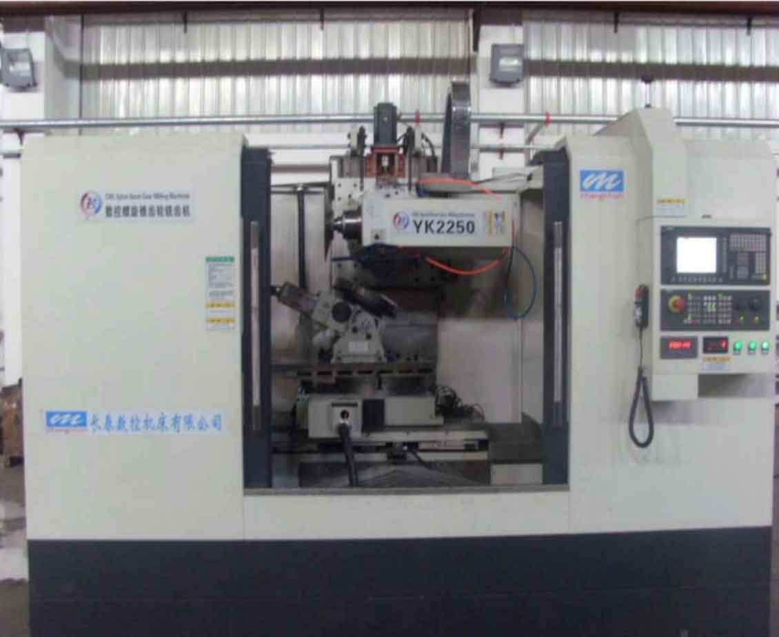
The demand for large-diameter, wide-face-width gear rings in heavy machinery, wind turbines, and marine propulsion systems has steadily increased. Manufacturing such monolithic components is often impractical due to machine tool travel limits and the sheer size of the blank. The segmented design approach, where the gear ring is divided into manageable arcs, is a standard solution. However, this introduces significant challenges for the gear milling process, as the segment’s geometric center cannot be aligned with the machine tool’s rotary table axis. This eccentric placement renders conventional radial infeed programming methods ineffective.
Traditional solutions for machining eccentric segments include generating the entire NC program for all teeth in a single, long block of code or using axial infeed with frame programming. The former lacks flexibility and is error-prone, while the latter, especially for wide face widths, leads to excessive tool overhang, reduced rigidity, and compromised surface finish. This paper proposes a novel and efficient method: an eccentric placement milling strategy employing a main program that calls a reusable tooth subroutine in a loop. This combines the program compactness of standard methods with the adaptability required for off-center workpieces. The core of the method lies in establishing a precise mathematical model for coordinate transformation and toolpath generation, which is then validated through comprehensive simulation using VERICUT, a powerful CNC simulation and optimization software. The feasibility is assessed by analyzing the residual material on the machined tooth flanks.
Mathematical Foundation for Eccentric Gear Milling
The proposed gear milling methodology is built upon a rigorous mathematical model comprising two interconnected parts: the Main Program Model, which handles the global positioning and indexing of the segment, and the Subroutine Model, which defines the precise tool motion for cutting a single tooth space.
1. Main Program Mathematical Model (Coordinate Transformation)
The workpiece setup is critical. The gear segment is positioned on the machine table with a deliberate offset. For ease of alignment, four datum surfaces (A, B, C, D) are machined on the ends of the blank. The workpiece coordinate system $x_c y_c z_c$ is established with its origin $O_c$ at the segment’s geometric center and $z_c$ pointing vertically upward. The machine’s programming coordinate system (and rotary table center) is at point $O$. The key is to align the $y_c$ axis with the line connecting $O_c$ and $O$. The eccentricity distance is $OO_c = d$. The initial tool position is set at point $P_0$, located at the intersection of the $y_c$ axis and the gear addendum circle of radius $R$.
The main program’s logic is to machine a tooth space located at an angular position $\theta$ from the initial $y_c$-axis. To use a single, generic tooth subroutine, the programming coordinate system must be transformed. The sequence is as follows:
- The programming coordinate system $x_m y_m z_m$ is initially made coincident with $x_c y_c z_c$.
- To machine the tooth at angle $\theta$, the programming system is rotated by $-\theta$ around the $z_m$ axis, resulting in a new system $x_m^n y_m^n z_m^n$. In this rotated system, the tool’s starting reference point is $P_{0\theta}$.
- A translational shift is then applied to move the tool from $P_{0\theta}$ to the actual starting point $P_{\theta}$ for the tooth at angle $\theta$.
The required translation vector $^{n}\vec{P_{0\theta}P_{\theta}}$ is derived from geometry. In the base $x_m y_m z_m$ system, the position vectors are:
$$ \vec{OP_0} = \begin{bmatrix} 0 \\ R – d \end{bmatrix}, \quad \vec{OP_{\theta}} = \begin{bmatrix} -R\sin\theta \\ R\cos\theta – d \end{bmatrix} $$
After applying the rotation matrix $M$ for angle $\theta$,
$$ M = \begin{bmatrix} \cos\theta & \sin\theta \\ -\sin\theta & \cos\theta \end{bmatrix}, $$
the vectors in the rotated system $x_m^n y_m^n z_m^n$ become:
$$ ^{n}\vec{OP_{0\theta}} = \begin{bmatrix} 0 \\ R – d \end{bmatrix}, \quad ^{n}\vec{OP_{\theta}} = M \cdot \vec{OP_{\theta}} = \begin{bmatrix} -d\sin\theta \\ d\cos\theta – d \end{bmatrix}. $$
Therefore, the required translation is:
$$ ^{n}\vec{P_{0\theta}P_{\theta}} = ^{n}\vec{OP_{\theta}} – ^{n}\vec{OP_{0\theta}} = \begin{bmatrix} -d\sin\theta \\ d(\cos\theta – 1) \end{bmatrix}. $$
This elegant result shows the compensation depends solely on the eccentricity $d$ and the index angle $\theta$, not on the gear radius $R$. This translation, combined with the rotation, allows the same tooth subroutine to be correctly positioned for any tooth on the eccentric segment.
2. Subroutine Mathematical Model (Tool Path Generation)
The subroutine defines the tool motion for milling one complete tooth space, typically involving roughing (slotting), semi-finishing, and finishing of the flanks, and finishing of the root. The focus here is on the flank milling operations, which often employ side-milling (end milling) where the tool’s side cutting edges are engaged. For high-quality gear milling, a 4-axis swarf milling strategy is ideal, where the tool axis remains tangent to the tooth flank surface.
The tooth flank surface $S$ is defined as a vector function of two parameters: $u$ (along the profile/height direction) and $v$ (along the face width direction):
$$ S(u,v) = [x(u,v), y(u,v), z(u,v)]^T. $$
For an involute surface, the partial derivatives $S_u = \frac{\partial S}{\partial u}$ and $S_v = \frac{\partial S}{\partial v}$ are non-parallel. The unit normal vector $n$ at any point $S(u_0, v_0)$ is:
$$ n(u_0, v_0) = \frac{S_u(u_0, v_0) \times S_v(u_0, v_0)}{\lVert S_u(u_0, v_0) \times S_v(u_0, v_0) \rVert}. $$
In swarf gear milling, the tool axis is aligned with this normal vector. Therefore, the tool center (CL point) must be offset from the contact point (CC point) along $n$ by half the tool diameter $D$:
$$ S_t(u_0, v_0) = S(u_0, v_0) + \frac{D}{2} \cdot n(u_0, v_0). $$
Furthermore, the tool axis orientation must account for the segment’s rotation. The local tool tilt angle $\beta$ relative to the Z-axis, derived from the surface geometry, is:
$$ \beta(u_0, v_0) = \arctan\left( \text{relevant component of } S_u(u_0, v_0) \right). $$
The sign of $\beta$ is positive for one flank and negative for the other. When the subroutine is called for a tooth at index angle $\theta$, the effective rotary axis command for a 4-axis machine (with rotation about the Z-axis) becomes $C = \theta + \beta$. For machines with RTCP (Rotation Around Tool Center Point) functionality, the subroutine can be written using tool axis vector commands (I, J, K), and the control automatically compensates for the workpiece rotation.
The following table summarizes the key parameters and equations of the mathematical model:
| Component | Key Parameter | Mathematical Expression | Description |
|---|---|---|---|
| Main Program | Eccentricity | $d = OO_c$ | Distance from table center to gear segment center. |
| Index Angle | $\theta$ | Angular position of target tooth from reference. | |
| Translation Vector | $^{n}\vec{P_{0\theta}P_{\theta}} = [-d\sin\theta,\ d(\cos\theta – 1)]^T$ | Compensation move after coordinate rotation. | |
| Subroutine | Flank Surface | $S(u,v)$ | Parametric definition of gear tooth flank. |
| Surface Normal | $n(u,v) = \frac{S_u \times S_v}{\lVert S_u \times S_v \rVert}$ | Unit normal vector at any point on the flank. | |
| Tool Center Position | $S_t(u,v) = S(u,v) + \frac{D}{2} \cdot n(u,v)$ | CL data point for swarf milling. | |
| Tool Axis Orientation | $C = \theta + \beta(u,v)$ or Tool Vector $= n(u,v)$ | 4-axis rotary command or 5-axis vector command. |
VERICUT Simulation and Validation
To validate the mathematical model and the eccentric placement gear milling strategy, a detailed simulation was constructed in VERICUT. A segment representing 1/12th of a large gear (Number of Teeth $Z=84$, Module $m_n=32$ mm, Pitch Diameter ~ 2688 mm) was modeled. The eccentricity was set to $d = 1000$ mm. The machine tool environment was a DMU 200 P 5-axis machining center.
1. Simulation Setup in VERICUT
The virtual setup mirrors the theoretical model. The gear segment, held by a fixture, is mounted on the rotary table (C-axis) with its center offset by 1000 mm from the table center. The programming zero (G54) is set at the rotary table center $O$. The machine’s Y-axis passes through the center of the initial reference tooth space. The VERICUT project includes accurate models of the machine kinematics, the cutter (a series of tools for roughing and finishing), the fixture, and the stock material.
2. NC Program Structure
The NC program was structured according to the developed model:
- Main Program: A macro-driven program that loops through the desired number of teeth. For each tooth index $i$ and corresponding angle $\theta_i$, it calculates the translation using the derived formula, executes the coordinate system rotation (e.g.,
ROT Z ROT=-θ), applies the translation (e.g.,TRANS X[...] Y[...]), and then calls the tooth machining subroutine. - Subroutine: A self-contained program that machines one tooth space. It contains:
- Roughing Cycle: Axial plunging or pocketing operations to remove bulk material.
- Flank Semi-Finishing/Finishing: A series of tool paths where the tool follows calculated CL points $S_t(u,v)$ with appropriate axis orientation ($C$ angle or vector). The tool moves along the face width ($v$ direction) at different profile heights ($u$ values).
- Root Finishing: A separate pass with a ball-nose end mill to machine the fillet.
3. Simulation Results and Analysis
The simulation successfully executed the complete gear milling process for multiple teeth on the eccentric segment. The material removal was visually correct for roughing, semi-finishing, and finishing operations. The swarf milling tool paths correctly engaged the flanks.
The conclusive validation was performed using VERICUT’s “Auto-Diff” module. This module compares the simulated machined stock (the “as-cut” geometry) with the designed CAD model (the “design” geometry). It performs a volumetric comparison and graphically highlights areas of excess material (remaining stock) and areas of deficient material (gouging).
The comparison was conducted with two different residue thresholds:
| Residue Threshold | Observation on Tooth Flanks | Observation on Tooth Root | Observation on Tooth Tip | Conclusion |
|---|---|---|---|---|
| 0.04 mm | Uniform, minimal residual material across all machined flanks. | Uniform residual material present, as expected from a separate finishing pass. | Minor “overcut” indications (<0.07 mm). | Flank milling accuracy is high and consistent. |
| 0.06 mm | No residual material highlighted on any flank. | Small, isolated areas of residue remain. | Minor “overcut” indications (<0.07 mm). | Flanks are fully within the 0.06 mm tolerance. Root finish requires process optimization. |
Critical Analysis of Results:
- Flank Accuracy: The uniform and minimal residue on the flanks across all angular positions ($\theta$) proves the correctness of the coordinate transformation model (main program) and the toolpath generation model (subroutine). The eccentric placement gear milling strategy successfully produces geometrically accurate teeth.
- Root Residuals: The higher residual in the root region is attributed to the use of a ball-nose end mill for this operation. The discrete step-over and the tool geometry inherently leave a cusp height. This is a characteristic of the chosen finishing method, not a flaw in the eccentric placement strategy. It can be reduced by optimizing the toolpath stepover or using a dedicated root-form cutter.
- Tip “Overcut”: The indicated overcut at the tooth tip is a simulation artifact. The gear segment stock model was a simple rectangular block. The tip “overcut” actually represents the unmachined stock material lying outside the gear’s addendum circle. Since the tip is not machined in this operation, this discrepancy is expected and confirms the simulation is correctly identifying the difference between the final stock and the design model.
Discussion and Practical Considerations for Gear Milling
The successful simulation validates the core method. However, transitioning to physical production requires addressing several practical aspects of gear milling.
1. Workpiece Setup and Datum Establishment: The precision of the entire process hinges on accurately establishing the workpiece coordinate system relative to the machine’s rotary center. The four datum faces (A, B, C, D) must be machined prior to gear milling and used with a precision probe to set the workpiece zero $O_c$ and align the $y_c$ axis. Any error here directly translates into a systematic tooth positioning error.
2. Toolpath Optimization within the Subroutine: The mathematical model provides the correct tool center and orientation. The quality of the final surface depends on the strategy for generating the sequence of $(u,v)$ points.
$$ \text{Optimization Parameters: } \Delta u \text{ (profile step), } \Delta v \text{ (feed direction step), tool lead/lag angles.} $$
A finer $\Delta u$ provides a closer approximation to the ideal involute but increases program length. The subroutine should be optimized for chatter-free cutting, considering the varying engagement conditions due to eccentricity.
3. Machine Tool Requirements: The method is suitable for 4-axis or 5-axis CNC milling centers with a rotary table. For 4-axis machines, the model using $C=\theta+\beta$ is applied. For 5-axis machines with RTCP, the tool vector programming is more straightforward. The machine’s kinematic accuracy, especially the rotary axis positional accuracy, is critical.
4. Extension to Helical and Bevel Gears: The fundamental principle of coordinate transformation for eccentric placement is general. For helical gear milling, the subroutine model becomes more complex as the tool axis orientation has two tilt angles (lead angle and profile tilt). The surface normal calculation $n(u,v)$ and the corresponding tool axis vector would incorporate the helix. Similarly, for bevel gears, the model would need to account for the changing profile along the face width.
Conclusion
This research presents a robust and practical solution for the gear milling of large-diameter, wide-face-width segmented gear rings that must be machined in an eccentric position on the worktable. The method elegantly solves the problem by decoupling the global positioning of the segment from the local cutting actions for a single tooth.
The cornerstone of the method is a two-part mathematical model: 1) A main program model that performs rotary and translational transformations to reposition the CNC’s coordinate system for each tooth based on the simple equations $X_{trans}=-d\sin\theta$ and $Y_{trans}=d(\cos\theta – 1)$; 2) A subroutine model that generates precise swarf milling toolpaths using the gear flank’s parametric equations to control tool center location and axis orientation.
The comprehensive VERICUT simulation, based on a realistic gear segment and machine model, provided definitive validation. The Auto-Diff analysis confirmed that the machined tooth flanks from multiple, eccentrically-positioned teeth were geometrically accurate and consistent, with flank residuals well within acceptable tolerances. Minor residuals in the tooth root were identified as a function of the chosen finishing toolpath, not the eccentric placement strategy itself.
In summary, the eccentric placement gear milling method using a main program to call a reusable subroutine is both theoretically sound and practically feasible. It offers significant advantages in program management, flexibility, and reliability over generating monolithic code for an entire segment. This approach enables the efficient and accurate manufacturing of large segmented gear rings on standard CNC machining centers, expanding the capabilities of modern gear milling technology.