
In the realm of precision mechanical engineering, the manufacture of thin-walled annular gears presents a formidable challenge, primarily due to the persistent issue of dimensional distortion during heat treatment. My extensive experience in this field has solidified the understanding that controlling these heat treatment defects is not merely a procedural step but a critical discipline that determines the functional integrity and service life of the final component. The phenomenon where a carefully machined gear emerges from the quench tank with unacceptable levels of out-of-roundness or size change is a classic and costly manifestation of uncontrolled thermal and transformation stresses. This article delves deep into the mechanistic roots of these distortions and outlines a comprehensive, first-principles strategy for their mitigation, incorporating analytical models, practical process tables, and proven fixturing techniques.
The core problem stems from the asymmetrical geometry of a thin-walled internal gear. Unlike a solid shaft, its large diameter-to-wall-thickness ratio creates a structure inherently unstable under the severe thermal gradients and phase transformations of carburizing and quenching. The primary heat treatment defects we observe are non-uniform dimensional changes, specifically elliptical distortion (ovality) and bore shrinkage, which directly compromise the gear’s meshing accuracy, load distribution, and noise characteristics. Tolerances for such components are often within microns, making even minor distortion unacceptable.
Deconstructing the Distortion Mechanism: Stresses at Play
To effectively combat distortion, one must first understand the internal stresses that drive it. During heat treatment, two major stress types are generated:
- Thermal Stress ($\sigma_{th}$): Arises from differential thermal contraction/expansion due to temperature gradients. During quenching, the surface cools and contracts rapidly while the core is still hot and expanded, placing the surface in tension and the core in compression.
- Transformation Stress ($\sigma_{tr}$): Results from volumetric changes during phase transformations (e.g., austenite to martensite). Martensitic transformation involves a volume expansion. If transformation occurs non-uniformly—surface first, then core—it creates complex stress states that can overwhelm the material’s yield strength.
The net residual stress ($\sigma_{res}$) and consequent distortion are the plastic, non-recoverable outcomes of these superimposed stresses exceeding the material’s high-temperature yield point. For a thin-walled ring, this often manifests as a change in radius. The final bore diameter ($D_f$) can be related to the initial diameter ($D_i$) and the average circumferential strain ($\epsilon_{\theta}$) by:
$$D_f = D_i (1 + \epsilon_{\theta})$$
where $\epsilon_{\theta}$ is a complex function of thermal gradient, transformation kinetics, and material flow stress.
A multitude of factors feed into this equation, each a potential source of variability and a contributor to heat treatment defects. I have categorized them for systematic analysis:
| Factor Category | Specific Elements | Mechanism of Influence on Distortion |
|---|---|---|
| Material & Metallurgical | Chemical composition band, hardenability, grain size, segregation, inclusion content. | Affects phase transformation uniformity, Ms temperature, and flow stress, leading to non-symmetric volumetric changes. |
| Initial Manufacturing Stresses | Residual stresses from forging, rolling, machining (turning, hobbing, shaving). | Pre-existing stresses are relieved or redistributed during heating, causing unpredictable shape changes. Machining can induce anisotropic surface stresses. |
| Part Geometry & Symmetry | Wall thickness uniformity, diameter-to-thickness ratio, asymmetry of features (keyways, bolt holes). | Creates non-uniform thermal mass, leading to varying cooling rates. Asymmetries act as stress concentrators and distortion initiators. |
| Heat Treatment Process | Heating rate, carburizing uniformity, quenching medium (oil speed, temperature), agitation, part orientation during quench. | Directly controls the magnitude and symmetry of thermal gradients and transformation sequences. Non-uniform carburization creates varying Ms points. Improper quench direction promotes non-axisymmetric cooling. |
| Fixturing & Support | Use of racks, baskets, mandrels, or support rings during high-temperature phases and quench. | Physically constrains the part against distortion during its most plastic (low yield strength) state. Critical for thin-walled components. |
A Strategic Framework for Distortion Control
Eliminating heat treatment defects requires a holistic strategy that addresses the entire manufacturing chain, not just the furnace. Here is the multi-stage approach I have developed and validated.
Stage 1: Pre-Heat Treatment Conditioning
The goal is to present a stable, stress-free, and uniform workpiece to the carburizing furnace.
- Normalizing or Forgings: A proper normalizing cycle after forging is non-negotiable. It refines the grain structure and homogenizes the microstructure.
- Stress Relieving: A sub-critical annealing or stress-relieving cycle after rough machining is crucial. This step eliminates the bulk of machining-induced stresses. For critical components, I often specify a stabilizing temper between rough and finish machining.
- Symmetrical Machining: Work with the design and machining teams to ensure machining passes are as symmetrical as possible. For internal gears, finishing the bore and teeth in a single setup or with minimal re-clamping reduces anisotropic stress introduction.
Stage 2: Controlled Carburizing
Uniform case depth is paramount. Non-uniform carburization leads to areas with different carbon concentrations, which subsequently have different Martensite Start (Ms) temperatures and transform at different times during quench, creating severe transformation stresses.
The Ms temperature can be estimated using an empirical formula like:
$$M_s(^{\circ}C) = 539 – 423C – 30.4Mn – 12.1Cr – 17.7Ni – 7.5Mo$$
where the element symbols represent weight percent. A variation in surface carbon (C) of just 0.1% can shift Ms by over 40°C, drastically altering transformation timing. Therefore, precise atmosphere control, proper spacing, and consistent furnace circulation are essential to avoid this root cause of heat treatment defects.
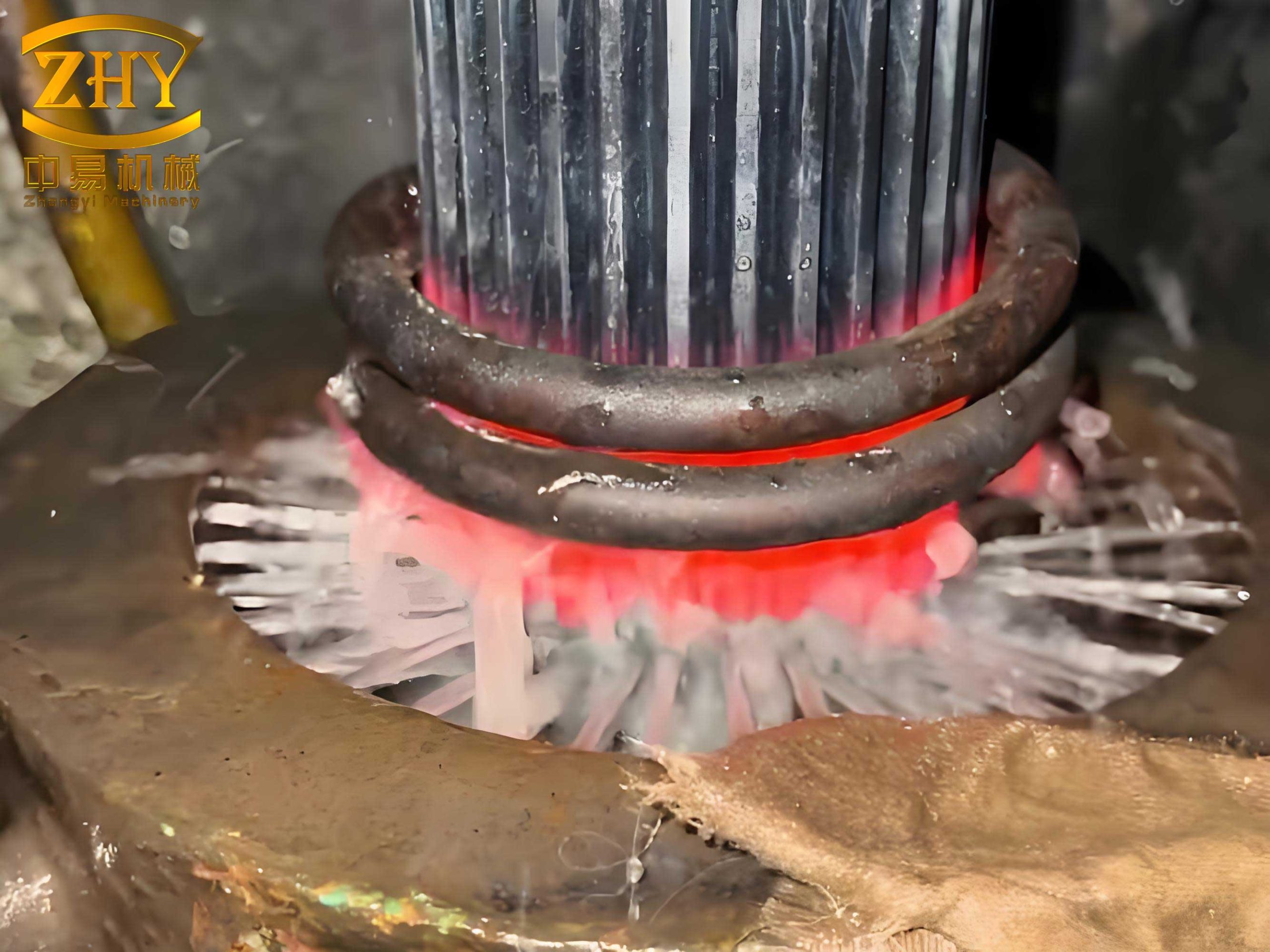
Stage 3: The Critical Quench: Engineering Uniformity
This is the most critical phase. The objective is to achieve the most axisymmetric cooling possible.
| Parameter | Typical Problem | Optimized Approach |
|---|---|---|
| Orientation | Parts laid flat in a basket; oil flow is impeded, causing top/bottom and side-to-side cooling differences. | Quench with the central axis vertical. Suspend gears on a mandrel or rack, allowing oil to flow freely over both inner and outer diameters and across the faces uniformly. |
| Fixturing/Mandrel | Free quenching allows bore to contract uncontrollably and potentially asymmetrically. | Use an expendable or reusable solid mandrel that fits snugly inside the bore during the quench. It physically prevents inward collapse and ensures roundness. The mandrel material must have a similar thermal expansion coefficient to minimize sticking. |
| Support Ring | A less constrained alternative to a full mandrel, but still effective for controlling ovality. | A robust steel ring is inserted inside the gear bore before quenching. It supports the thin wall against the fluid冲击 forces and thermal stresses, acting as an internal die. It is removed only after the part has cooled to room temperature after tempering. |
| Quenchant Selection | Using a fast, aggressive oil for thick sections, which imposes too severe a gradient on thin walls. | Select a quenching oil with a lower maximum cooling speed or use a martempering (hot oil) process. Martempering involves quenching into a salt or oil bath at a temperature just above Ms, holding to equalize temperature, then air cooling, drastically reducing thermal stress. |
| Agitation | Poor or directional agitation creates “soft spots” and variable cooling. | Ensure strong, uniform, and omnidirectional agitation of the quenchant. Use of agitators with flow directors in the quench tank is recommended. |
The effectiveness of a support ring can be conceptualized by considering the thin wall as a slender column. The critical buckling stress ($\sigma_{cr}$) under the compressive thermal/transformation stresses during quench is given by Euler’s formula for a ring:
$$\sigma_{cr} = \frac{E}{1-\nu^2} \left(\frac{t}{R}\right)^2$$
where $E$ is Young’s modulus, $\nu$ is Poisson’s ratio, $t$ is wall thickness, and $R$ is the mean radius. The support ring effectively increases the buckling resistance by providing lateral constraint, preventing the instability that leads to ovality, one of the most common heat treatment defects in these components.
Stage 4: Tempering and Final Stabilization
Tempering is not just for hardness adjustment; it is a vital stress-relief step. The process of tempering relieves quench stresses through thermal activation. A well-conducted temper allows micro-plastic flow to occur, reducing residual stresses. For high-precision gears, a double or even triple temper is often beneficial. Furthermore, the support ring or mandrel should remain in place throughout the first tempering cycle. Removing it before tempering allows the still-present residual stresses to distort the part freely. By tempering with the constraint in place, the part is stress-relieved in its “correct” geometrical shape.
Case Study Analysis: From Problem to Solution
Let’s analyze a typical scenario mirroring common industrial challenges. A thin-walled internal gear, material: SAE 8620 (similar to 20CrMnMo), required a case depth of 0.6-0.7mm and a hardness of 55-60 HRC. The initial process flow was: Forging → Normalize → Machine → Carburize & Quench → Temper. Post-treatment, the bore exhibited severe ovality of 0.3-1.0mm, far exceeding the 0.20mm specification—a clear and costly heat treatment defect.
Root Cause Investigation: Initial improvements focused on material quality, normalizing, and adding a stress-relief cycle after rough machining. While helpful, they only reduced ovality to 0.2-0.7mm. The pivotal insight came from observing the quenching method: gears were stacked horizontally in a basket. This led to non-uniform oil flow, causing differential cooling rates around the circumference. The thin wall, with nothing to restrain it, yielded asymmetrically to the unbalanced thermal and transformation stresses.
Implementation of the Solution: The core corrective action was twofold:
- Vertical Orientation: Gears were placed on a rack with their axis vertical during both carburizing and quenching.
- Internal Support Ring: A precisely machined carbon steel ring was inserted into the bore of each gear before the quench cycle. This ring remained in place throughout the quench and the subsequent tempering operation.
The result was transformative. The support ring provided the necessary internal constraint to counteract the asymmetric contracting forces, ensuring the bore retained its roundness during the most vulnerable phase. After tempering and ring removal, the measured ovality was consistently below 0.20mm, eliminating the heat treatment defects and achieving full specification compliance.
| Process Stage | Key Control Measure | Primary Effect on Distortion |
|---|---|---|
| Material & Machining | Stabilizing temper post-rough machining. | Eliminates ~60-80% of machining-induced stresses, providing a stable baseline. |
| Carburizing | Vertical racking, uniform atmosphere. | Ensures symmetrical case depth, preventing localized variations in Ms and transformation stress. |
| Quenching | Vertical orientation + Internal Support Ring/Mandrel. | Single most effective action. Enforces axisymmetric cooling and physically prevents bore collapse and ovality. |
| Tempering | Tempering with constraint in place. | Relieves quench stresses while the part is held in its nominal geometry, “locking in” the correct shape. |
Conclusion and Forward Perspective
The battle against distortion in thin-walled internal gears is won through a philosophy of preemption and control, not correction. Viewing the part as a system interacting with thermal and mechanical forces is key. The integration of proactive steps—from stress-relief cycles to intelligent fixturing like support rings—constitutes a robust defense against heat treatment defects. The vertical quenching of a gear supported internally is a profoundly effective tactic, as it directly counteracts the fundamental instability of the thin-wall geometry under thermal shock.
Future advancements lie in predictive modeling. Using finite element analysis (FEA) software to simulate temperature fields, phase transformations, and stress evolution during the entire heat treatment cycle allows for virtual prototyping of processes and fixtures. One can simulate the effect of a support ring, optimize its fit and thermal properties, and predict final dimensional outcomes before any metal is cut or heated. This digital twin approach, combined with the empirical principles outlined here, represents the next frontier in virtually eliminating heat treatment defects and achieving true first-part-correct manufacturing for even the most challenging geometries.