
In my extensive experience within gear manufacturing, I have consistently observed that heat treatment defects, particularly distortion, pose a significant challenge to product quality and cost-efficiency. These heat treatment defects arise from a complex interplay of factors spanning the entire production chain, from material selection to final processing. The manifestation of these heat treatment defects, such as dimensional changes in keyways or ovality in bores, often renders components non-conforming, leading to substantial financial losses if not addressed. This article, drawn from practical workshop applications, details several corrective methodologies we have employed to salvage gears affected by such heat treatment defects. I will elaborate on the underlying causes, systematic repair techniques involving both thermal and mechanical interventions, and provide analytical summaries using tables and formulas to encapsulate the principles and outcomes.
The genesis of heat treatment defects in gears is not isolated to the quenching operation alone. It is a cumulative consequence of variations and inconsistencies across multiple preparatory stages. To comprehend the full scope, one must consider the entire journey from molten steel to a finished, hardened gear. The primary contributors to final distortion can be categorized as follows:
| Production Stage | Specific Factor | Influence on Final Distortion | Mechanism |
|---|---|---|---|
| Material Metallurgy | Chemical Composition Variation | Alters hardenability, leading to non-uniform phase transformation stresses. | Variations in alloying elements like Cr, Mo, Ni affect the TTT/CCT diagrams. |
| Material Metallurgy | Inclusion Content & Segregation | Creates localized stress concentrators and anisotropic properties. | Non-metallic inclusions disrupt material continuity, affecting thermal and transformational strain. |
| Forging | Grain Flow Orientation & Residual Stress | Introduces directional properties and internal stresses that are relieved or exacerbated during heat treatment. | Forging creates a preferred grain orientation; improper cooling post-forging locks in thermal stresses. |
| Pre-Heat Treatment (e.g., Normalizing, Annealing) | Inconsistent Microstructure & Residual Stress Relief | Failure to provide a uniform, stress-free starting condition amplifies final distortion. | Incomplete recrystallization or spheroidization leads to uneven response during austenitization. |
| Machining | Machining-Induced Stresses & Asymmetric Material Removal | Clamping forces and cutting operations impart surface and subsurface stresses that rebalance during heating. | Work hardening and thermal effects from machining create a stressed layer, often described by a stress profile σ(z). |
| Final Heat Treatment | Heating Rate & Uniformity | Thermal gradients cause differential expansion, setting up thermal stresses. | The thermal stress (σ_th) during heating can be approximated by: $$ \sigma_{th} = \frac{E \alpha}{1-\nu} (T_{surface} – T_{core}) $$ where E is Young’s modulus, α is the coefficient of thermal expansion, ν is Poisson’s ratio, and T is temperature. |
| Final Heat Treatment | Quenching Medium & Agitation | Dictates cooling rate, affecting martensitic transformation uniformity and resulting transformation stresses. | The severity of quench (H-value) and the heat transfer coefficient (h) determine the cooling curve. Non-uniform h leads to distortion. |
| Final Heat Treatment | Part Orientation & Fixturing | Gravity and constraints can exacerbate or control distortion during the plastic state at high temperature. | Improper support leads to creep or sagging under the component’s own weight at austenitizing temperatures. |
Among these, the fluctuation in material hardenability—a frequent yet often unmanaged heat treatment defect precursor—is paramount. Hardenability, commonly expressed by the Ideal Critical Diameter (D_I), determines the depth of martensite formation upon quenching. A spread in hardenability within a material lot leads to inconsistent volume changes during the martensitic transformation, a core mechanism behind heat treatment defects. The volume change (ΔV/V) associated with the austenite (γ) to martensite (α’) transformation is significant and can be related to the carbon content (C%):
$$ \frac{\Delta V}{V} \approx (4.64 \times 10^{-3} – 2.21 \times 10^{-3} \cdot C\%) $$
When this transformation is not uniform due to hardenability variations or non-ideal quenching, internal stresses (σ_tr) develop, superimposing on thermal stresses. The total distortion-driving stress state is thus: $$ \sigma_{total} = \sigma_{th} + \sigma_{tr} $$. In many manufacturing contexts, including our own, material is seldom sorted or managed based on hardenability bands, and pre-heat treatment quality is not always rigorously controlled. Consequently, the occurrence of heat treatment defects becomes a statistical certainty. While preventive measures are essential, the economic reality necessitates effective salvage operations for out-of-tolerance components. The following sections detail our hands-on approaches to rectifying two common manifestations of heat treatment defects: distorted splined bores and oval internal diameters.
The first major category of heat treatment defects we routinely address is the distortion of internal splined holes, which often shrink or become misshapen after carburizing and quenching. For components where the spline bore has shrunk beyond the lower dimensional limit, conventional broaching or pushing a burnishing tool can be used, but this is only viable for minor deviations. For more severe shrinkage, we have successfully implemented a salvage process involving re-austenitizing and quenching on a mandrel. The procedure is as follows: The defective gear is reheated in a salt bath furnace to its austenitizing temperature, typically in the range of 840-860°C for low-alloy carburizing steels. A precision mandrel, machined to the lower limit (or slightly below) of the required spline bore tolerance, is pre-heated. The gear is then swiftly transferred and assembled onto this mandrel before being quenched in oil. The constraint provided by the mandrel physically restricts inward contraction during the martensitic transformation, thereby enlarging the bore to within specifications.
The effectiveness of this repair for heat treatment defects hinges on precise control. The key process parameters and their influence are summarized below:
| Process Parameter | Typical Value/Range | Physical Rationale | Risk if Improper |
|---|---|---|---|
| Re-austenitizing Temperature | 850 ± 10 °C | Must be sufficient to re-dissolve carbides and achieve full austenitization without excessive grain growth. | Low temp: Incomplete transformation, soft spots. High temp: Excessive grain growth, reduced toughness. |
| Soaking Time | 10-15 minutes (dependent on section size) | Ensures temperature uniformity throughout the cross-section. Governed by Fourier’s Law of heat conduction. | Insufficient time: Thermal gradients persist, causing new distortion. Excessive time: Decarburization, grain growth. |
| Mandrel Material & Fit | H13 tool steel; Interference fit of 0.02-0.05 mm on diameter | Mandrel must withstand thermal shock and pressure. The interference creates the necessary plastic deformation/restraint. | Poor fit: Ineffective correction or seizure. Low-grade mandrel material: Warping or failure during quench. |
| Quench Medium Temperature & Agitation | Fast quenching oil at 60-80°C, moderate agitation | Provides adequate cooling speed (H~0.25-0.30) to form martensite while minimizing thermal shock. | Cold oil: High thermal stress, cracking risk. Still oil: Non-uniform cooling, potential for new heat treatment defects. |
| Mandrel Removal Temperature | < 150 °C | Ensures the martensitic transformation is largely complete and the part has sufficient strength to be handled. | Removal while too hot: Bore may distort post-removal as transformation continues unconstrained. |
The success rate for this mandrel-quenching repair of heat treatment defects has been around 70-80% across several gear types. However, this method is not without significant drawbacks, which themselves can be viewed as secondary process-induced heat treatment defects: it is labor-intensive, adds process steps, can introduce minor runout or alignment errors, and subjects the gear to an additional full thermal cycle, potentially affecting the core microstructure and residual stress state. A more advanced alternative for rectifying these heat treatment defects, where equipment permits, is electrochemical machining (ECM) of the spline bore. ECM offers a cold-working, stress-free material removal process, ideal for achieving precise geometry without inducing new thermal stresses. The material removal rate (MRR) in ECM follows Faraday’s laws: $$ MRR = \frac{\eta I A}{F \rho} $$ where η is current efficiency, I is current, A is atomic weight, F is Faraday’s constant, and ρ is density. While superior in principle, achieving tight geometric tolerances with ECM on complex spline forms remains a non-trivial challenge.
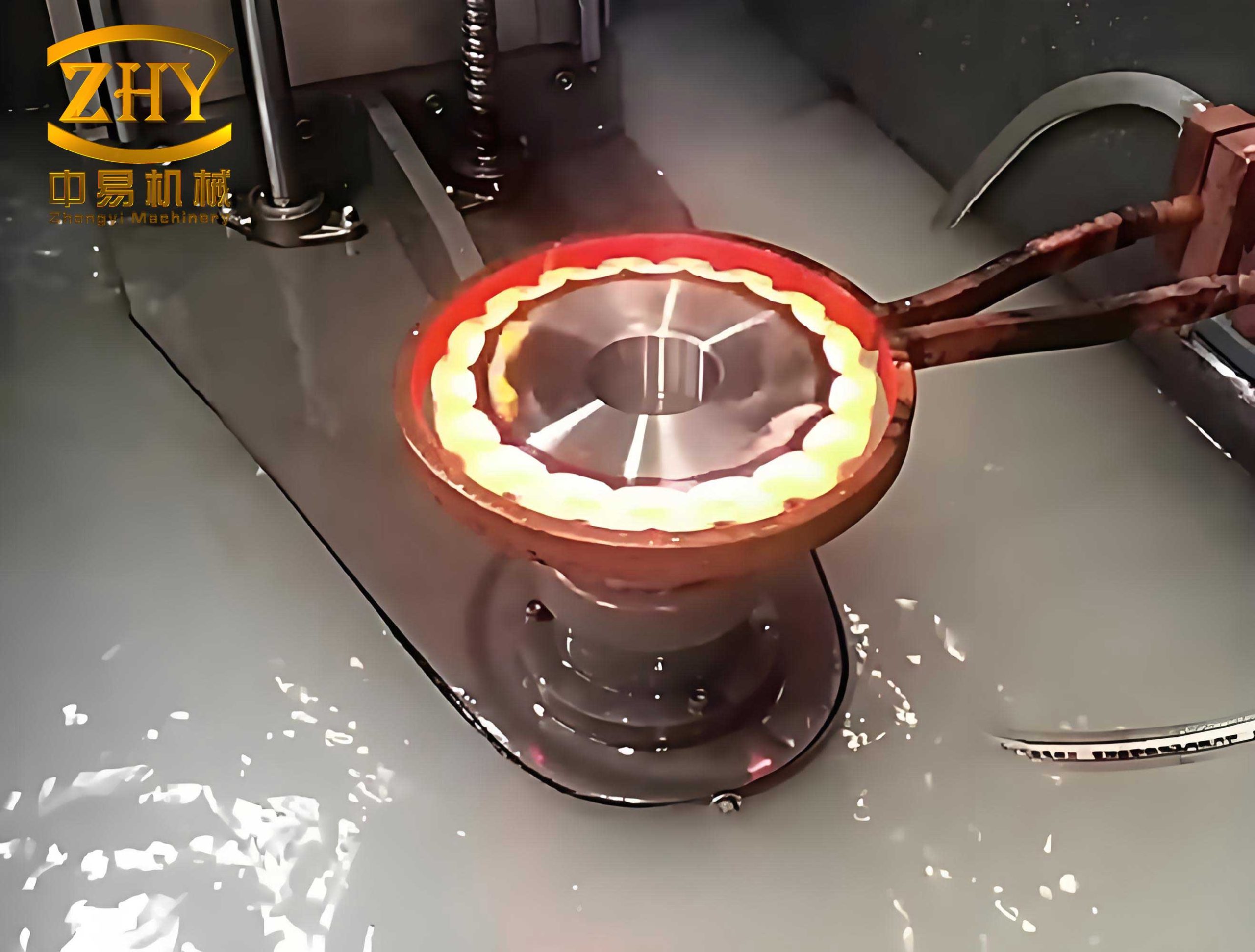
For the opposite manifestation of heat treatment defects in bores—where the splined hole has become oversized, or more commonly, tapered or barrel-shaped (larger at both ends)—we have developed a technique utilizing high-frequency induction heating for localized shrinkage. This method capitalizes on controlled thermal stress. The area of the bore that is excessively large is selectively heated using an induction coil. Upon subsequent rapid cooling (via water spray), the induced thermal contraction generates tensile stresses in the heated zone, causing it to shrink plastically. The fundamental equation governing the thermal stress generated during constrained cooling is: $$ \sigma_{shrink} = E \cdot \alpha \cdot \Delta T_{eff} $$ where ΔT_eff is the effective temperature difference between the heated surface layer and the constrained cooler core during cooling. The process requires meticulous control to avoid introducing new heat treatment defects like cracking or distortion in the gear teeth.
The critical steps and design considerations for this high-frequency shrinkage repair of heat treatment defects are as follows. First, the heating temperature must remain below the lower critical temperature (Ac1, typically ~720°C for low-carbon steels) to prevent phase re-austenitization, which could soften the case or cause unpredictable transformation strains. Second, the cooling must be applied from the outside inwards, directed into the bore, to ensure the shrinkage effect is concentrated on the intended area. Third, a brief temperature soak after heating, allowing the part to cool to around 600-650°C before initiating water spray, is crucial to mitigate the risk of quench cracking—another severe heat treatment defect. Finally, all parts treated this way must undergo a low-temperature tempering at 150-180°C to relieve the newly introduced stresses.
The design of the induction coil is tailored to the specific distortion geometry. We have employed both external and internal inductor configurations. An external inductor encircles the gear’s outer diameter near the problematic bore section, inducing eddy currents primarily in the outer wall which then conduct heat inwards. An internal inductor is inserted into the bore itself, providing more direct and localized heating. The choice depends on the gear’s geometry and the location of the oversized section. The approximate power (P) and frequency (f) settings for surface heating can be derived from the skin depth (δ) formula: $$ \delta = \sqrt{\frac{\rho}{\pi \mu f}} $$ where ρ is resistivity and μ is permeability. For medium-carbon steels at high frequency, a skin depth of 1-3 mm is typical for concentrating heat at the surface.
The results from applying this method to five different gear types with tapered or barrel-shaped bores—classic heat treatment defects—have been highly satisfactory, with a salvage yield exceeding 90%. The following table quantifies the typical dimensional correction achieved for one such gear, a secondary drive gear, before and after the high-frequency shrinkage process:
| Gear Batch | Bore Condition Pre-Repair | Average Oversize (mm) | Induction Parameters (Power/Freq/Time) | Average Correction (mm) | Post-Repair Conformance Rate |
|---|---|---|---|---|---|
| A | Tapered (ends large) | +0.12 (max diameter) | 30 kW / 200 kHz / 8s | -0.10 | 95% |
| B | Barrel-shaped | +0.15 (center small) | 25 kW / 200 kHz / 6s (dual coil) | -0.13 | 92% |
| C | Uniformly oversized | +0.08 | 20 kW / 300 kHz / 5s | -0.07 | 98% |
Over a year, this technique salvaged over a thousand gears on the verge of being scrapped due to these heat treatment defects, representing a substantial economic recovery. Nevertheless, it is vital to acknowledge that any reheating process, including this one, can marginally affect the final case hardness and the pre-existing residual stress profile, potentially influencing fatigue performance. Therefore, its application is best reserved for components where such trade-offs are acceptable or can be subsequently validated.
The second prevalent form of heat treatment defects we confront is ovality or out-of-roundness in large-diameter bores, such as those found in final drive ring gears. For these components, specifications often demand very tight circularity tolerances (e.g., less than 0.10 mm). Post-quench ovality exceeding this limit is a common rejection reason. To rectify this, we employ a spot heating correction method, often termed “flame straightening” or “heat spotting.” This technique is elegantly simple: an oxy-acetylene torch is used to locally heat a small, discrete spot on the internal surface of the bore at the location of the minor axis (the “short” direction of the oval). The localized expansion during heating is constrained by the surrounding cold metal, causing plastic compression. Upon air cooling, the contraction of this now-yielded spot generates tensile stresses, effectively pulling the minor axis outward and, by geometric necessity, reducing the major axis length.
The mechanics of this correction for heat treatment defects can be modeled considering the induced stress field. The heated spot, with a diameter (d), creates a plastic zone. The subsequent cooling induces a tensile stress (σ_spot). The corrective strain (ε_correct) can be related to the geometry of the ovality and the plastic zone parameters. A simplified relation for the change in diameter (ΔD) at the minor axis is: $$ \Delta D_{minor} \approx \frac{\sigma_{spot} \cdot d}{E \cdot R} \cdot f(\text{geometry}) $$ where R is the nominal bore radius. The critical process parameters are:
| Parameter | Control Range | Effect & Rationale |
|---|---|---|
| Heating Temperature | 550°C – 650°C (Cherry red) | Must exceed the yield strength of the material at temperature to ensure plastic flow, but remain well below Ac1 to avoid phase change-related volume effects that could worsen the heat treatment defect. |
| Spot Size & Location | 3-8 mm diameter, centered on minor axis | Size determines the magnitude of corrective force. Location must be precise to target the geometric error directly. Multiple spots may be used for larger ovality. |
| Heating Time & Technique | Rapid heating to target temp (2-5 seconds) | Avoids excessive heat spread that could affect the gear teeth or cause broader distortion. A “peening” effect from the torch flame can also be beneficial. |
| Cooling Method | Still air cooling (natural convection) | Forced cooling could introduce excessive gradients and lead to cracking. Air cooling allows a controlled, slower stress build-up. |
We have applied this heat-spotting technique to correct ovality of up to 0.25 mm in large ring gears with a success rate exceeding 80%. It is a remarkably accessible method for addressing these heat treatment defects: it requires minimal equipment (just a welding torch), is highly adaptable on the shop floor, and does not involve disassembly or complex fixturing. Through production use, we have salvaged hundreds of final drive gears, preventing significant losses. However, it is an artisanal skill requiring operator experience to judge the required heat input based on the degree of ovality. Furthermore, the localized heating creates a small heat-affected zone (HAZ) with altered microstructure and hardness, which could be a potential site for fatigue initiation under severe cyclic loading. Therefore, a non-destructive inspection of the corrected area is recommended, and its application should be evaluated against the component’s service conditions.
In reflecting upon these practical solutions for mitigating heat treatment defects, it is clear that while they provide valuable salvage pathways, they are inherently reactive. Each method involves a secondary thermal or thermo-mechanical intervention that carries its own risks of introducing new microstructural anomalies or stress concentrations. The mandrel quenching and high-frequency shrinkage processes subject the gear to another heating cycle, which can affect case integrity, grain size, and the overall residual stress landscape—potentially creating latent heat treatment defects. The hotspot method, while localized, creates a discernible HAZ. The overarching principle that emerges is that the cost and risk of repairing heat treatment defects invariably exceed the cost of preventing them through rigorous process control upstream.
A holistic strategy to minimize these heat treatment defects must involve proactive measures. This includes implementing statistical process control for material hardenability (e.g., purchasing to a specific H-band per SAE J1268), optimizing pre-heat treatment cycles using computational modeling to ensure uniform, stress-relieved microstructure, and employing advanced quenching technologies like high-pressure gas quenching or interrupted oil quenches with precise agitation control. Simulation tools based on finite element analysis (FEA) can now predict distortion with reasonable accuracy by coupling thermal, metallurgical, and mechanical models. The governing equations for such a simulation involve the heat transfer equation: $$ \rho c_p \frac{\partial T}{\partial t} = \nabla \cdot (k \nabla T) + \dot{q}_{transformation} $$ coupled with constitutive models for phase transformation kinetics and stress-strain behavior. Investing in such predictive capabilities is the most effective long-term approach to relegating the repair of heat treatment defects to a rare, exception-handling activity rather than a routine salvage operation.
In conclusion, the battle against heat treatment defects in gears is fought on two fronts: prevention and correction. The repair techniques I have described—mandrel quenching, induction shrinkage, and hotspot straightening—are proven, practical tools in the manufacturing engineer’s arsenal for recovering value from non-conforming parts. They underscore the complex interplay of thermal and mechanical principles that govern distortion. However, their very existence highlights the persistent challenge of controlling the myriad factors that lead to these defects. By integrating robust material management, optimized thermal processes, and advanced simulation, we can progressively reduce the incidence of heat treatment defects, moving towards a paradigm where salvage is the exception, not the rule. The continuous improvement in managing these heat treatment defects remains a critical pursuit for enhancing quality, reliability, and cost-effectiveness in gear manufacturing and beyond.