
In the realm of hydraulic engineering and navigation structures, the challenge of efficiently moving vessels across significant changes in water elevation has driven continuous innovation. As I survey the landscape of modern ship lift technology, I observe a clear trajectory towards systems that offer greater reliability, efficiency, and adaptability to varying traffic demands. My focus has been drawn particularly to the vertical ship lift, a class of structure where the vessel-carrying receptacle, or caisson, moves along a vertical axis. Among these, the rack and pinion gear-driven vertical lift has emerged as a leading solution for high-head applications, exemplified by monumental projects worldwide. However, every engineering solution presents opportunities for refinement. In this comprehensive analysis, I will elaborate on a conceptual evolution of this established technology: a Dual-Rack and Pinion Vertical Ship Lift. This system reimagines the fundamental balance mechanism, promising to enhance operational efficiency and flexibility. I will delve into its principles, mechanical design, comparative advantages, and potential applications, supported by analytical models and tabular comparisons.
The historical development of ship lifts reveals a diverse array of solutions, each with inherent strengths and constraints. Fundamentally, they are categorized by the path of motion: inclined and vertical. Inclined ship lifts, where the caisson moves along a sloped ramp, can be further divided into longitudinal and transverse types based on the vessel’s orientation. While often simpler in concept for certain topographies, they require significantly more space and can involve complex transfer mechanisms. My interest, however, lies with vertical ship lifts due to their compact footprint and direct lifting action, making them ideal for sites with severe space constraints or very high lifts. Vertical lifts themselves have been realized in several forms:
| Type | Primary Balancing Principle | Key Advantages | Key Disadvantages | |
|---|---|---|---|---|
| Floating Caisson | Buoyancy of a submerged float | Simple force equilibrium; low lifting power needed. | Limited by float size and depth; sensitive to water level fluctuations. | |
| Hydraulic Piston | Water pressure in a cylinder-piston assembly | High force capability; smooth motion. | Complex sealing and maintenance; potential for fluid leakage. | |
| Wire Rope Hoist (Counterweight) | Counterweights connected via wire ropes and sheaves | Mature technology; significantly reduces motor power. | Rope wear and maintenance; requires high towers for rope draping; dynamic behavior can be complex. | |
| Rack and Pinion (Counterweight) | Counterweights, with drive via rack and pinion gear sets | Positive mechanical engagement; high positioning accuracy; excellent safety (e.g., mechanical safety nuts). | High manufacturing/precision demands; sensitive to structural deformation of support towers. |
From this comparison, it is evident that the rack and pinion gear system, despite its stringent precision requirements, offers unparalleled safety and control, which are paramount for lifting massive loads like a water-filled ship caisson. The core principle involves a linear gear (the rack) fixed to the load-bearing structure (e.g., a reinforced concrete tower) and a rotating gear (the pinion) mounted on the moving caisson. The motor drives the pinion, which then “climbs” or “descends” the stationary rack. The positive engagement eliminates slippage, a critical risk in purely rope-based systems. The celebrated Three Gorges Project ship lift in China stands as a testament to this technology’s viability on a grand scale, employing a rack and pinion gear drive combined with a mechanical screw-nut safety backup system.
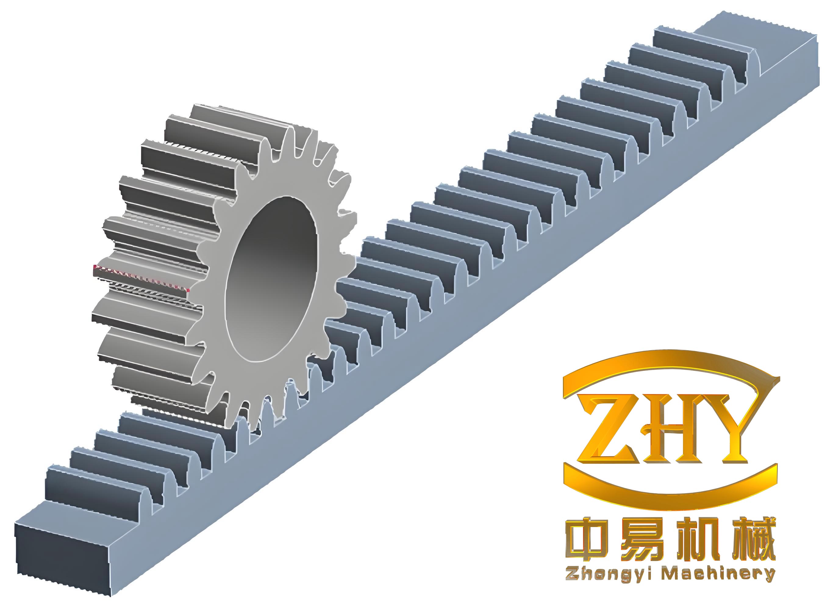
The fundamental working principle of a rack and pinion gear pair in this context is based on converting rotary motion into precise linear motion. The kinematic relationship is straightforward. For a pinion with pitch circle diameter $D_p$ and number of teeth $N$, the module $m$ (a fundamental parameter defining tooth size) is:
$$ m = \frac{D_p}{N} $$
The linear distance traveled by the caisson per one revolution of the pinion is equal to the pinion’s pitch circumference:
$$ \text{Travel per Revolution} = \pi D_p = \pi m N $$
Therefore, the vertical speed $v$ of the caisson is directly related to the rotational speed $n$ (in revolutions per second) of the pinion:
$$ v = n \cdot \pi D_p $$
The torque $T$ required at the pinion shaft to overcome the net lifting force $F_{\text{net}}$ (after accounting for counterweights) is:
$$ T = F_{\text{net}} \cdot \frac{D_p}{2} \cdot \frac{1}{\eta} $$
where $\eta$ is the efficiency of the rack and pinion gear pair and associated drivetrain. This simple yet robust mechanical relationship is the cornerstone of the system’s controllability.
However, the traditional rack and pinion vertical ship lift, as implemented, still relies on massive counterweight blocks to balance the weight of the caisson and its water payload. This is energy-efficient for lifting but represents a significant capital investment in steel or concrete weights, and their associated ropes, sheaves, and guide systems. My proposed conceptual evolution seeks to innovate precisely at this point. What if the counterweight’s function could be performed by another, fully functional caisson? This leads to the core idea of the Dual-Rack and Pinion Vertical Ship Lift.
Concept and Design of the Dual-Rack and Pinion System
The proposed system consists of two identical, symmetrically arranged ship caissons operating within adjacent shafts or guide structures. Unlike independent lifts, these two caissons are mechanically linked at their tops via a wire rope system running over large-diameter sheaves (pulleys) mounted on the support tower. This configuration creates a direct balance: as one caisson ascends, the other descends, and vice-versa. The drive force to initiate and control this motion is provided not by hoisting ropes, but by multiple, synchronized rack and pinion gear drives attached to each caisson.
The primary components of this system are:
- Twin Caissons: Structurally identical vessels designed to carry ships. They are the “moving counterweights” for each other.
- Rack and Pinion Gear Drive Units: Multiple sets per caisson, distributed along its length for load sharing and stability. Each unit comprises a fixed vertical rack attached to the tower structure and a motor-driven pinion assembly mounted on the caisson.
- Interconnecting Rope and Sheave System: A multi-rope, multi-sheave arrangement connecting the tops of the two caissons. This system ensures force equilibrium and synchronizes the vertical positions of the two caissons. The rope tension $T_r$ under static conditions for caissons of equal mass $M_c$ (including water) is:
$$ T_r = \frac{M_c \cdot g}{2 \cdot n_{\text{ropes}} \cdot \cos(\theta)} $$
where $g$ is gravity, $n_{\text{ropes}}$ is the number of rope pairs, and $\theta$ is any slight deviation from vertical. - Enhanced Braking Pinion: An innovation on the standard rack and pinion gear. The pinion is fabricated as a “disk-brake gear,” where high-strength, wear-resistant steel disks are integrally welded or forged onto the sides of the gear blank. This allows for the application of high-pressure caliper brakes directly onto these disks, providing a massive, fail-safe mechanical braking force that acts directly on the drive element engaging the rack.
- Water Filling/Evacuation System: Standard systems for matching caisson water level to that of the upstream or downstream approach channel.
The true ingenuity of this design lies in its operational flexibility, which I term “Modal Flexibility.” The system can operate in three distinct modes seamlessly:
| Operational Mode | Configuration | Use Case | Power Requirement |
|---|---|---|---|
| Dual-Line, Balanced Mode | Both caissons carry vessels moving in opposite directions. | Normal operation with balanced upstream/downstream traffic. | Minimal. Power is mainly to overcome friction, inertia, and water seal drag. Net lifting force $F_{\text{net}} \approx 0$. |
| Single-Line, Counterweight Mode | One caisson carries a vessel; the other is empty but serves as counterweight. | Traffic predominantly in one direction. | Low. Power needed for half the imbalanced mass (e.g., ship weight). |
| Single-Line, Independent Mode | One caisson operates; the other is mechanically locked in place. | Maintenance on one shaft; very low traffic. | High. Equivalent to lifting the full caisson mass without balance. Rarely used. |
Mathematical Modeling and Efficiency Analysis
To quantify the advantages, a comparative power analysis is essential. Let us define key parameters:
- $M_c$: Mass of one empty caisson.
- $M_w$: Mass of water in a full caisson.
- $M_s$: Mass of the ship.
- $\mu$: Coefficient of friction for guides, seals, etc.
- $\eta_g$: Efficiency of the rack and pinion gear and drivetrain.
- $v$: Lifting/lowering speed.
For a traditional counterweighted rack and pinion gear lift, the counterweight is typically designed to balance the caisson plus half its water payload ($M_c + 0.5M_w$). The net force to lift a caisson with a ship is primarily the weight of the ship plus the unbalanced half-water weight, plus friction:
$$ F_{\text{net, trad}} = (M_s + 0.5M_w)g + \mu \cdot (M_c + M_w + M_s)g $$
The required mechanical power at the pinion shafts is:
$$ P_{\text{mech, trad}} = F_{\text{net, trad}} \cdot v $$
For the proposed Dual-Rack and Pinion system in Dual-Line, Balanced Mode, the ideal net force is zero if both caissons carry ships of equal mass. In practice, there will be a difference $\Delta M_s$ between the masses of the two ships. The net force becomes:
$$ F_{\text{net, dual}} = (\Delta M_s)g + \mu \cdot [2(M_c + M_w) + M_{s1} + M_{s2}]g $$
The frictional term is larger because two caissons are moving, but the lifting term is only the ship mass difference. The mechanical power is:
$$ P_{\text{mech, dual}} = F_{\text{net, dual}} \cdot v $$
The efficiency gain is dramatic when $\Delta M_s$ is small. Consider a numerical example with $M_c = 8000$ t, $M_w = 2000$ t, $M_s = 1500 \pm 500$ t, $\mu=0.02$, $v=0.2$ m/s, $\eta_g=0.92$.
| Scenario | Net Force $F_{\text{net}}$ (kN) | Mech. Power $P_{\text{mech}}$ (kW) | Motor Power (kW) ($/\eta_g$) |
|---|---|---|---|
| Traditional: Lifting one ship | $(1500 + 1000)*9.81 + 0.02*(11500)*9.81 \approx 24,525 + 2,256 = 26,781$ | $26,781 * 0.2 = 5,356$ | $5,356 / 0.92 \approx 5,822$ |
| Dual-Line: Equal ships ($\Delta M_s=0$) | $0 + 0.02*[2*(10000) + 3000]*9.81 \approx 0 + 4,512 = 4,512$ | $4,512 * 0.2 = 902$ | $902 / 0.92 \approx 980$ |
| Dual-Line: Ship diff. 1000t ($\Delta M_s=1000$) | $(1000)*9.81 + 4,512 \approx 9,810 + 4,512 = 14,322$ | $14,322 * 0.2 = 2,864$ | $2,864 / 0.92 \approx 3,113$ |
This analysis shows a potential reduction in motor power demand by over 80% in the ideal balanced case, and nearly 50% even with a significant ship mass imbalance, compared to the traditional single-line design. This translates directly to lower energy consumption, smaller motors, and reduced peak electrical load.
Safety and Synchronization Considerations
The rack and pinion gear system is inherently safe due to positive engagement. The proposed design augments this with two layers of safety specific to the dual-caisson configuration. First, the interconnected rope system provides a passive, force-balancing safety net. If one drive system were to fail, the rope connection would prevent a catastrophic drop, as the other caisson acts as an anchor. Second, the disk-brake pinion provides a high-capacity, direct mechanical braking force on the drive element itself. The braking torque $T_b$ available is:
$$ T_b = n_{\text{calipers}} \cdot \mu_{\text{brake}} \cdot P_{\text{brake}} \cdot A_{\text{piston}} \cdot r_{\text{eff}} $$
where $r_{\text{eff}}$ is the effective radius of the brake disk. This torque acts directly on the rack and pinion gear interface to halt motion.
Synchronization between the two caissons is critical. While the rope system enforces gross positional synchronicity, fine control is managed by the multiple rack and pinion gear drives on each caisson. A centralized control system monitors the position, velocity, and load on each drive unit, adjusting motor torque in real-time to ensure the caissons remain level and the rope tension stays within designed bounds. The use of a common rack and pinion gear reference on the fixed tower provides an absolute positional feedback signal, enhancing control accuracy.
Comparative Advantages and Application Outlook
The Dual-Rack and Pinion Vertical Ship Lift concept synthesizes the strengths of existing technologies while introducing transformative flexibility. Its key advantages can be summarized as follows:
- Dramatically Improved Energy Efficiency: By using a second caisson as the counterweight, the system minimizes the net mass to be accelerated, cutting peak and average power demand substantially, as demonstrated in the mathematical model.
- Enhanced Operational Flexibility (Modal Flexibility): The ability to switch between dual-line and single-line modes allows the infrastructure to adapt optimally to fluctuating and asymmetric traffic patterns, maximizing throughput and utility.
- Inherent Safety: The combination of the fail-safe rope interconnection, the positive engagement of the rack and pinion gear, and the integrated disk-brake pinions creates a robust, multi-redundant safety architecture.
- Reduced Civil Works for Counterweights: Eliminating the need for massive concrete counterweight blocks and their associated pits and guide systems can simplify foundation design and reduce construction volume.
- High Reliability of Core Mechanism: It builds upon the proven, high-precision rack and pinion gear drive technology, which is known for its durability and positional accuracy.
The potential applications for this design are at sites with high navigation traffic volume and/or significant head differences. It is particularly suited for new projects on major inland waterways, large-scale canal systems, or as part of future hydropower complexes where navigation is a key requirement. While the initial mechanical and control system may be more complex than a simple counterweight system, the lifecycle benefits in terms of energy savings, operational adaptability, and traffic handling capacity present a compelling case.
In conclusion, the evolution of ship lift technology is moving towards smarter, more efficient, and more adaptable systems. The Dual-Rack and Pinion Vertical Ship Lift concept I have detailed here represents a significant step in that direction. By re-purposing the counterweight into a fully functional second caisson and leveraging the precise, powerful, and safe actuation of the rack and pinion gear, this design promises to set a new benchmark for performance in vertical ship lifting. Future research and development should focus on detailed dynamic simulation, optimization of the rope-sheave interconnection system, and the development of control algorithms for seamless mode transitions, paving the way for its realization in future world-class navigation projects.