
In my extensive experience within the automotive repair and manufacturing sector, I have consistently encountered significant challenges related to component wear, precision machining, and the quest for efficient production methods. One of the most persistent issues revolves around the premature failure of drivetrain components, particularly helical bevel gears used in differential assemblies, and the detrimental effects of crankshaft bending in internal combustion engines. This narrative details my firsthand involvement in pioneering a thermal rolling process for helical bevel gear production and delves into the critical analysis of crankshaft alignment methodologies, emphasizing the profound impact these innovations have on durability and performance.
The conventional machining of a helical bevel gear is a complex, time-consuming operation requiring specialized hobbling or milling equipment, which is often unavailable in smaller repair facilities. This scarcity leads to protracted lead times, material wastage, and frequently, subpar gear quality that fails to meet the rigorous demands of vehicular operation. Driven by necessity, my team and I embarked on an experimental journey to develop an alternative: the hot-rolling technique for forming helical bevel gears. This method not only promised enhanced efficiency but also aimed to achieve superior geometrical accuracy.
The fundamental principle of our helical bevel gear hot-rolling process involves plastically deforming a heated gear blank against a master gear roll. The gear blank, typically forged from alloy steel such as AISI 8620, is first rough-machined to a near-net shape. It is then heated uniformly to a critical austenitizing temperature range, typically between 950°C and 1050°C, using an oxy-acetylene torch or induction heater. This temperature ensures adequate material ductility for plastic flow without incipient melting. The heated blank is mounted on a mandrel attached to a modified lathe carriage. A master helical bevel gear, hardened and ground to precise specifications, is chucked in the lathe spindle. As the master gear rotates at a controlled speed of 8 to 12 revolutions per minute, the carriage is advanced, pressing the hot blank against it. The rolling action, combined with the application of a water-based coolant spray on the master roll to manage its temperature, causes the blank’s material to flow into the conjugate tooth spaces of the master, forming the helical bevel gear teeth through a combination of extrusion and forging. The process is usually completed in two stages: an initial rough-forming pass followed by a finishing and burnishing pass to improve surface finish and dimensional tolerance. The total processing time per helical bevel gear averages between 1.5 and 2 hours, representing a substantial reduction compared to traditional cutting.
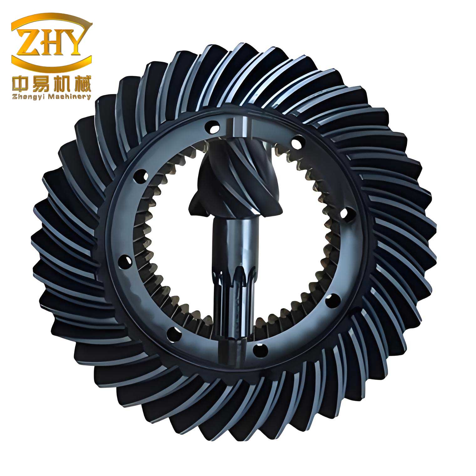
To quantify the specifications of the helical bevel gear we successfully produced for a heavy-duty truck application, the following table encapsulates its key geometric parameters:
| Parameter | Symbol | Value | Unit |
|---|---|---|---|
| Transverse Diametral Pitch at Pitch Apex | \(P_t\) | 6.350 | teeth/inch |
| Number of Teeth (Pinion) | \(z_1\) | 11 | – |
| Pressure Angle | \(\alpha\) | 20 | degrees |
| Pitch Cone Angle | \(\delta_1\) | 15.5 | degrees |
| Shaft Angle | \(\Sigma\) | 90 | degrees |
| Whole Depth | \(h_t\) | 12.7 | mm |
| Mean Spiral Angle | \(\beta_m\) | 35 | degrees |
| Hand of Spiral | – | Left | – |
| Number of Teeth (Gear) | \(z_2\) | 41 | – |
The geometry of a helical bevel gear is governed by a set of interrelated formulas. The pitch diameter \(d_1\) for the pinion is given by:
$$d_1 = \frac{z_1}{P_t}$$
The virtual number of teeth \(z_v\), which influences tooth strength and contact patterns, is calculated considering the spiral angle:
$$z_v = \frac{z}{\cos^3 \beta_m \cos \delta}$$
The mean cone distance \(R_m\) is a critical parameter for determining bending stress:
$$R_m = \frac{d_1}{2 \sin \delta_1} – 0.5 b$$
where \(b\) is the face width. The formative gear ratio \(i\) for this orthogonal helical bevel gear pair is:
$$i = \frac{z_2}{z_1} = \frac{\sin \delta_2}{\sin \delta_1}$$
and since \(\Sigma = \delta_1 + \delta_2 = 90^\circ\), we have \(\delta_2 = 90^\circ – \delta_1\).
The success of this helical bevel gear hot-rolling process hinges on precise control over thermal and mechanical variables. The following table outlines the primary process parameters and their optimized ranges established through our experimentation:
| Process Parameter | Optimized Range | Influence on Helical Bevel Gear Quality | |
|---|---|---|---|
| Blank Heating Temperature | 1000 ± 50 °C | Dictates material flow stress; too low causes incomplete form filling, too high promotes grain growth. | |
| Rolling Speed (Master Gear) | 10 ± 2 RPM | Affects strain rate and heat generation; lower speeds improve form accuracy but increase cycle time. | |
| Feed Rate (Carriage Advance) | 0.5 – 1.0 mm/rev | Controls the reduction per pass; critical for managing rolling force and preventing defects. | |
| Coolant Flow Rate | 5 – 10 L/min | Prevents overheating of the master helical bevel gear roll, preserving its hardness and geometry. | |
| Total Reduction (Diameter) | 4 – 6 mm | Ensures complete tooth form generation and proper densification of the helical bevel gear material. |
The metallurgical transformation during the hot-rolling of a helical bevel gear is profound. The process refines the austenite grain structure through dynamic recrystallization, which can be modeled by the Zener-Hollomon parameter \(Z\):
$$Z = \dot{\epsilon} \exp\left(\frac{Q}{RT}\right)$$
where \(\dot{\epsilon}\) is the strain rate, \(Q\) is the activation energy for hot deformation, \(R\) is the universal gas constant, and \(T\) is the absolute rolling temperature. A finer grain size generally enhances the fatigue strength of the final helical bevel gear. Post-rolling, the gear is subjected to controlled cooling and subsequent heat treatment—carburizing, quenching, and tempering—to achieve a case-hardened surface with a tough core, essential for withstanding the high contact and bending stresses in service.
The helical bevel gears produced via this method were installed in the differential of a heavy-duty haul truck operating in mountainous terrain with a gross combination weight exceeding 30 tons. After a monitored service period covering over 20,000 kilometers, no significant issues such as pitting, spalling, or abnormal noise were observed. This performance validates the hot-rolling approach for manufacturing a durable and precise helical bevel gear. However, for volume production, the development of dedicated, high-stiffness rolling mills and the engineering of optimized master gear rolls are imperative. Further refinement of the process window, including computer-controlled temperature and force feedback systems, is the logical next step.
Parallel to the challenges in gear manufacturing, the issue of crankshaft bending and its consequential asymmetric wear—often termed “偏磨” or biased wear—presents a major reliability concern in engine overhaul. In my practice, I have analyzed numerous cases where crankshaft bending, often due to thermal stresses, overloading, or previous improper handling, leads to localized excessive wear on main bearing journals. This biased wear not only necessitates more frequent regrinding but can drastically shorten the total service life of the crankshaft.
Consider a typical in-line six-cylinder engine crankshaft. When the first main journal exhibits biased wear, its diameter becomes elliptical rather than perfectly circular. To restore cylindricity during a regrinding operation, the amount of material removed must be at least equal to the maximum wear depth. If the minimum diameter after wear is \(D_{min}\) and the nominal diameter is \(D_{nom}\), the required grinding allowance \(\Delta\) to achieve a true circle is:
$$\Delta \geq D_{nom} – D_{min}$$
For instance, if \(D_{nom} = 80.00 \, \text{mm}\) and post-wear measurement shows \(D_{min} = 79.70 \, \text{mm}\), then \(\Delta \geq 0.30 \, \text{mm}\). Standard regrinding sizes often come in increments of 0.25 mm (e.g., -0.25 mm, -0.50 mm, -0.75 mm, -1.00 mm). Removing 0.30 mm might force the use of the -0.50 mm oversize bearing, effectively consuming two life-cycle steps in one repair, a significant reduction in longevity. The table below illustrates a hypothetical wear scenario and its implications:
| Main Journal # | Nominal Diameter (mm) | Measured Min. Diameter after Wear (mm) | Required Grinding Allowance (mm) | Resultant Repair Size Step | Material Life Consumed |
|---|---|---|---|---|---|
| 1 | 80.00 | 79.70 | 0.30 | 4th ( -0.75 mm) | 3 steps |
| 2 | 80.00 | 79.85 | 0.15 | 2nd ( -0.25 mm) | 1 step | 3 | 80.00 | 79.90 | 0.10 | 1st ( -0.25 mm)* | 1 step |
*Minimum removal often defaults to the smallest available oversize.
Furthermore, crankshaft bending induces secondary problems. The misalignment propagates to ancillary components, causing uneven wear on the timing gear drive and compromising the sealing efficiency of the rear oil seal, leading to leaks. The bending stress \(\sigma_b\) in a crankshaft journal due to an offset load can be approximated by the formula for a beam in pure bending:
$$\sigma_b = \frac{M y}{I}$$
where \(M\) is the bending moment, \(y\) is the distance from the neutral axis (half the diameter), and \(I\) is the area moment of inertia for a circular cross-section, \(I = \frac{\pi d^4}{64}\). This stress concentration accelerates fatigue and wear.
The traditional method for straightening a bent crankshaft involves using a hydraulic press to apply a reverse bending force at the point of maximum deflection. While this can eliminate the gross visual bend, it often creates a series of localized plastic deformations or “kinks” along the crankshaft’s length. Consequently, although the crankshaft may appear straight when measured at the main journals, its rotational axis is no longer a smooth, continuous line. This irregular axis disrupts the dynamic balancing of the crankshaft assembly, potentially leading to severe engine vibration post-installation. The press-straightening process can be modeled as inducing a corrective plastic strain \(\epsilon_p\) over a small volume, which must counter the existing residual strain from bending. However, controlling this precisely is difficult.
Based on my observations and trials, I advocate for an alternative straightening technique: the strategic peening or cold-working of the crankshaft’s crankpin webs (or cheek areas). This method involves applying controlled, localized impacts using a rounded tool on the concave side of the bent crank throw. The induced compressive stresses in the surface layer of the web cause a slight elongation on that side, gradually pulling the crankshaft back into alignment without creating sharp curvature changes. This process better preserves the original axis geometry. The principle can be related to the concept of introducing a bending moment \(M_s\) through surface stress:
$$M_s = \int_A \sigma_s y \, dA$$
where \(\sigma_s\) is the induced compressive stress from peening and \(A\) is the cross-sectional area of the web. By sequentially treating multiple throws, overall alignment is restored.
Perhaps the most critical step in crankshaft reconditioning is the establishment of the grinding datum. When regrinding the journals, the crankshaft must be positioned and rotated based on undamaged, true reference surfaces. These are typically the front gear journal (which drives the timing gears) and the rear flange outer diameter. The axis defined by these two reference cylinders represents the original, intended rotational centerline of the crankshaft. The grinding wheel must be dressed and the workpiece set up relative to this axis. A common but detrimental mistake is to use the already worn and possibly eccentric main journals themselves for alignment during the initial setup on the grinding machine. While this might seem to minimize the initial stock removal, it effectively transfers the axis of rotation from the true datum to the erroneous axis defined by the worn surfaces. The result is a crankshaft whose mass center is offset from its new geometric axis of rotation, destroying its inherent dynamic balance. The unbalance force \(F_u\) generated at an operating speed \(\omega\) is given by:
$$F_u = m e \omega^2$$
where \(m\) is the mass of the crankshaft and \(e\) is the offset (eccentricity) between the center of mass and the axis of rotation. This force increases with the square of the rotational speed, explaining the severe vibration that can manifest at high RPM.
The interplay between precision component manufacturing, like that for a helical bevel gear, and accurate repair techniques, as for crankshafts, underscores a unified philosophy in automotive engineering: the preservation of design intent and geometrical integrity. The hot-rolling process for a helical bevel gear succeeds because it replicates the conjugate form of a master gear with high fidelity under controlled conditions. Similarly, proper crankshaft straightening and grinding rely on respecting and restoring the original datums and axes. Both endeavors require a deep understanding of material science, mechanics, and precision engineering.
To further elaborate on the helical bevel gear topic, let’s explore the contact mechanics between the teeth of a helical bevel gear pair. The contact pattern under load is elliptical, and its size and location are crucial for noise reduction and load capacity. The Hertzian contact stress \(\sigma_H\) at the pitch point can be estimated using:
$$\sigma_H = \sqrt{\frac{F_n}{\pi b’} \cdot \frac{\frac{1}{\rho_1} + \frac{1}{\rho_2}}{\frac{1-\nu_1^2}{E_1} + \frac{1-\nu_2^2}{E_2}}}$$
where \(F_n\) is the normal tooth load, \(b’\) is the effective face width, \(\rho_1\) and \(\rho_2\) are the radii of curvature of the pinion and gear teeth at the contact point, \(\nu\) is Poisson’s ratio, and \(E\) is the modulus of elasticity. For a helical bevel gear, the radii of curvature are functions of the spiral angle and cone distance. The hot-rolling process, by promoting a favorable grain flow lines following the tooth profile, can enhance resistance to this contact stress, a key advantage over cut gears where the grain structure is often intersected.
The development of the hot-rolling process for helical bevel gears also involved extensive tribological consideration. The interface between the hot blank and the cooler master gear roll involves complex friction and heat transfer. A coefficient of friction \(\mu\) in the range of 0.2-0.3 under mixed lubrication conditions (from the coolant) was assumed in our force calculations. The rolling force \(F_r\) required can be roughly correlated to the flow stress of the material \(\sigma_f\) at the rolling temperature and the projected contact area \(A_c\):
$$F_r \approx k \cdot \sigma_f \cdot A_c$$
where \(k\) is a factor accounting for geometry and friction. Monitoring this force was essential to prevent overloading the lathe structure and to ensure consistent deformation across every helical bevel gear produced.
In conclusion, the experimental adoption of hot-rolling for manufacturing helical bevel gears has demonstrated a viable path toward overcoming equipment limitations in automotive repair workshops. It marries the principles of metal forming with the precise requirements of gear geometry, yielding components of commendable strength and accuracy. Concurrently, a meticulous approach to crankshaft reconditioning—eschewing crude press straightening in favor of web-peening techniques and rigorously adhering to original datums during grinding—is paramount for ensuring engine smoothness and longevity. Both these technical narratives, from the fabrication of a robust helical bevel gear to the careful restoration of a crankshaft, highlight that innovation in repair methodologies is not merely about fixing components but about reinvigorating them to meet or exceed their designed performance envelope. The journey toward perfecting the helical bevel gear hot-rolling process continues, promising further integration of advanced process control and material science for even greater reliability and efficiency in the future.