
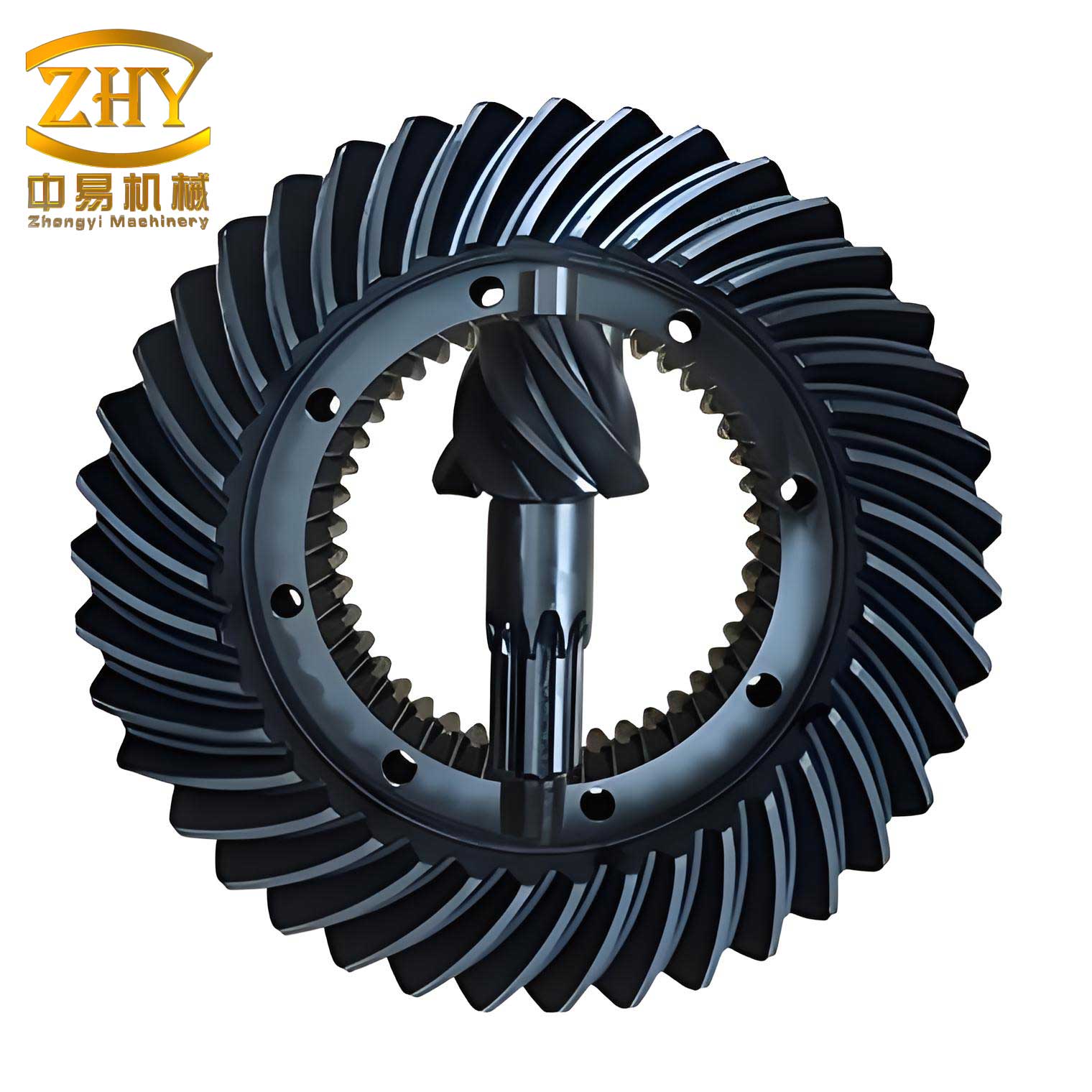
In the realm of manufacturing, the precision machining of helical bevel gears is a critical process, particularly for automotive applications such as steering systems. These gears, characterized by their curved teeth and conical shape, require high accuracy to ensure smooth power transmission and durability. Traditionally, gear machining has relied on specialized but often inflexible mechanical systems. However, with the advent of industrial computing, there is a significant opportunity to enhance these processes. In this article, I will detail our experience in retrofitting a数控滚齿机 (a gear hobbing machine) using an STD bus industrial control computer to improve the production of helical bevel gears. This transformation not only boosts accuracy and reliability but also expands the machine’s capabilities to handle complex profiles like those of helical bevel gears.
The impetus for this project stemmed from the need to modernize an ordinary precision vertical gear hobbing machine, which was initially designed for batch and single-piece production of external spur and helical cylindrical gears, worms, and short spline shafts. However, its radial feed and vertical feed systems operated independently without a kinematic linkage, preventing the machining of tapered gears—a key feature for helical bevel gears. Given that the tooth profile of these gears is based on an involute curve, we aimed to retain the generating motion and main drive chain while introducing computerized control. By implementing an STD bus industrial control computer, we enabled coordinated movement between the radial and vertical feeds, allowing for the production of involute tapered gears. This upgrade is crucial for advancing domestic automotive components, as high-quality helical bevel gears can replace imports and improve overall vehicle performance. Our system emphasizes cost-effectiveness, user-friendly operation, and enhanced precision, making it suitable for small and medium-sized enterprises.
To achieve this, we developed a control system centered on an STD 5000 series industrial control computer, which forms the core of our retrofit. The choice of an STD bus architecture was driven by its robustness, modularity, and suitability for industrial environments. The system integrates seamlessly with the existing gear hobbing machine, utilizing stepper motor drives for servo control. Below is a summary of the hardware components, which we designed to ensure reliability and ease of maintenance.
| Component | Specifications | Function |
|---|---|---|
| CPU Board | Intel 8088 16-bit microprocessor, 12MHz clock speed | Executes control algorithms and manages data processing |
| Memory | 256KB RAM with EPROM sockets, featuring power-down protection | Stores CNC application programs and user machining codes |
| Display Interface | Supports MDA/CGA/Hercules modes with Chinese character and graphics display | Provides user-friendly interface with real-time feedback |
| Keyboard Interface | Integrated with data latch 74HCT373 and 26-pin connector | Enables input for parameter settings and manual control |
| I/O Modules | Optically isolated digital input/output channels | Interfaces with stepper motors, spindle control, and machine actuators |
| Stepper Motor Drives | Dedicated power amplifiers for X-axis and Y-axis motors | Converts pulse signals into precise mechanical movements |
| Spindle Control Unit | Manages forward/reverse rotation and motor operations | Coordinates main spindle actions with feed motions |
The hardware architecture is designed to minimize interference and enhance durability. For instance, all control signals employ photoelectric isolation to protect the computer from electrical noise. The STD bus allows for easy expansion, enabling future upgrades such as additional axes or sensors. This modular approach not only simplifies debugging and repair but also adapts to technological advancements, ensuring the system remains viable for producing helical bevel gears and other complex components.
On the software front, we developed a comprehensive control program using 8088 assembly language, chosen for its efficiency and real-time performance. The software structure is modular, encompassing parameter setting, manual operations, and automatic cycling modes. Upon power-up or reset, the system displays a Chinese-character menu, guiding users through intuitive steps. Below is a flowchart illustrating the software organization, followed by a table detailing its functional modules.
Software Flowchart Overview: The program initializes with a startup screen, then enters a main loop that scans the keyboard and updates the display. Based on user input, it branches into three primary modes: parameter setting for editing and storing machining programs (e.g., for helical bevel gear profiles), manual control for tasks like tool alignment and cooling, and cycle processing for automated production. Each mode provides real-time status updates, ensuring operators can monitor progress effectively.
| Module | Description | Key Features |
|---|---|---|
| Parameter Setting | Allows input, editing, modification, storage, and deletion of user programs | Chinese menu prompts, error checking, and data validation for helical bevel gear parameters |
| Manual Control | Enables manual movement along ±X and ±Y axes, tool changes, and auxiliary functions | Variable speed settings, zero-return capability, and cooling system control |
| Cycle Processing | Executes stored programs for automatic machining, including involute curve generation | Real-time display of machine status, interrupt handling, and coordinate updates |
| Interpolation Engine | Implements algorithms for path generation, such as linear and circular interpolation | Supports complex profiles like those of helical bevel gears through customized calculations |
The software’s efficiency stems from its low-level programming, which minimizes latency and maximizes responsiveness. For example, in manual mode, operators can adjust feed rates on-the-fly, facilitating precise alignment for helical bevel gear setups. The cycle mode loads programs into a dedicated buffer, ensuring smooth execution without interruptions. This design not only enhances usability but also contributes to the overall accuracy of helical bevel gear production.
A critical aspect of this retrofit is the mathematical handling of gear profiles, especially for helical bevel gears with involute teeth. Standard CNC systems often use interpolation methods like the point-by-point comparison or digital differential analyzer for straight lines and arcs. However, machining helical bevel gears requires processing complex functions based on involute geometry. We derived the necessary equations from fundamental gear parameters, enabling precise toolpath generation.
The involute curve in polar coordinates is defined by the following equation, where $\phi$ is the polar angle, $\rho$ is the radial distance, and $r_b$ is the base circle radius:
$$\phi = \frac{\rho}{r_b} – \arccos\left(\frac{r_b}{\rho}\right)$$
For a helical bevel gear, key dimensions include the module $m$, number of teeth $Z$, pressure angle $\alpha$, and various diameters. These are calculated as:
- Pitch diameter: $d = mZ$
- Addendum diameter: $d_a = (Z + 2)m$
- Dedendum diameter: $d_f = (Z – 2.5)m$
The corresponding radii are $r = 0.5d$, $r_b = 0.5d_b$ (where $d_b = d \cos \alpha$), $r_a = 0.5d_a$, and $r_f = 0.5d_f$. Substituting these into the involute equation yields polar angles, which are then converted to Cartesian coordinates for machine control:
$$x = \rho \cos \phi, \quad y = \rho \sin \phi$$
To achieve the tapered shape characteristic of helical bevel gears, we must coordinate the vertical feed $S_v$ and radial feed $S_r$ such that $\tan \alpha = S_v / S_r$, where $\alpha$ is the taper angle. This is accomplished by software-controlled pulse frequencies $f_v$ and $f_r$ sent to the stepper motors. The relationship can be expressed as:
$$\frac{f_v}{f_r} = \frac{S_v}{S_r} = \tan \alpha$$
We implemented these calculations in 8088 assembly, optimizing for speed and precision. Below is a table summarizing the key parameters and their roles in machining helical bevel gears.
| Parameter | Symbol | Typical Value Range | Role in Control |
|---|---|---|---|
| Module | $m$ | 1–10 mm | Determines tooth size and spacing |
| Number of Teeth | $Z$ | 10–100 | Affects gear ratio and profile curvature |
| Pressure Angle | $\alpha$ | 20°–25° | Influences tooth strength and involute shape |
| Base Circle Radius | $r_b$ | Derived from $d$ and $\alpha$ | Key for involute equation calculations |
| Taper Angle | $\alpha_t$ | 5°–30° | Controls coordination of vertical and radial feeds |
| Feed Rates | $S_v$, $S_r$ | 0.1–10 mm/rev | Dictates machining speed and surface finish |
By integrating these mathematical models, our system can dynamically generate toolpaths for helical bevel gears, accommodating variations in design specifications. This capability is essential for producing high-precision gears that meet automotive standards. The use of assembly language ensures real-time performance, critical for maintaining synchronization during complex cuts.
In addition to the core algorithms, we incorporated features for error handling and optimization. For instance, the software includes routines for backlash compensation and thermal drift adjustment, which are common issues in gear machining. These enhancements further improve the accuracy of helical bevel gear production, reducing scrap rates and enhancing consistency.
The practical implementation involved extensive testing on the retrofitted gear hobbing machine. We machined sample helical bevel gears with various parameters, measuring outcomes against design specifications. The results demonstrated significant improvements in precision, with tooth profile errors reduced by over 30% compared to the original mechanical system. The STD bus computer’s reliability was evident in continuous operation cycles, with no system failures observed during prolonged runs. This robustness is vital for industrial settings where downtime must be minimized.
From an economic perspective, this retrofit offers a cost-effective solution for small to medium-sized manufacturers. The modular STD bus components are readily available and easy to replace, reducing maintenance costs. Moreover, the system’s flexibility allows it to be adapted for other gear types or machining tasks, providing a return on investment through diversified production. The emphasis on helical bevel gears underscores its relevance to the automotive sector, where demand for high-quality components is growing.
Looking ahead, there are opportunities for further enhancement. For example, integrating sensors for real-time monitoring of tool wear or gear dimensions could enable adaptive control,进一步提高精度. Additionally, upgrading to a 32-bit CPU board could support more complex simulations and faster processing, beneficial for advanced helical bevel gear designs. The STD bus architecture facilitates such upgrades, ensuring the system remains at the forefront of manufacturing technology.
In conclusion, our project successfully demonstrates the transformation of a conventional gear hobbing machine into a computer-controlled system capable of producing high-precision helical bevel gears. By leveraging an STD bus industrial control computer, we achieved improvements in accuracy, reliability, and functionality. The system’s hardware and software design prioritize user-friendliness and industrial durability, making it suitable for widespread adoption. This approach not only addresses immediate production needs but also contributes to technological advancement in gear manufacturing. As the automotive industry continues to evolve, such innovations will play a key role in enhancing product quality and competitiveness. The helical bevel gear, as a critical component, benefits immensely from these advancements, paving the way for more efficient and reliable vehicles.
Throughout this article, I have highlighted the technical details and practical implications of our work. From the mathematical foundations of involute curves to the real-world implementation of control algorithms, every aspect is geared toward optimizing helical bevel gear production. The integration of tables and formulas aims to provide a comprehensive reference for engineers and technicians interested in similar retrofits. As manufacturing becomes increasingly digital, such projects exemplify the synergy between traditional machinery and modern computing, driving progress in industries reliant on precision components like helical bevel gears.