
In our steel rail production line, straightening is one of the most critical processes. For a long time, our operation relied solely on a six-roll straightening machine. This single machine was responsible for correcting both the vertical and lateral curvature of the rails, placing an enormous load on the equipment. This excessive load led to frequent failures, such as broken universal joint crossheads and poor meshing within the reducer gearboxes, while simultaneously compromising the quality of the straightened rail. As rail production volumes increased and quality demands became more stringent, this limitation became a significant bottleneck. The need to enhance rail straightening quality and reduce the burden on the existing six-roll machine was urgent.
After studying various straightening equipment configurations, we decided to install a new seven-roll straightening machine downstream of the existing six-roll unit, forming a combined straightening system. The strategic division of labor was clear: the six-roll machine would primarily handle vertical bending, while the newly added seven-roll machine would focus on correcting lateral bending. This approach successfully improved the overall straightening quality and significantly alleviated the operational load on the older six-roll machine, a benefit confirmed over a year of operation. However, as the two machines were not designed and manufactured simultaneously, inherent issues surfaced, primarily concerning speed synchronization and the durability of the new machine’s drivetrain. The core problems identified were:
1. Speed mismatch between the two straightening machines, causing operational interference.
2. Insufficient strength of the original helical bevel gear set in the seven-roll machine’s transmission system.
To address these challenges, our technical team undertook a series of adjustments and redesigns. The following sections detail the theoretical and practical basis for our modifications, focusing on the critical role and redesign of the helical bevel gear system.
1. Resolution of Speed Synchronization
The close proximity of the two straighteners makes precise speed matching paramount for smooth operation. A significant speed discrepancy leads to severe mechanical interference, generating substantial parasitic stresses, particularly detrimental to the newer seven-roll unit. Following a major maintenance overhaul, this interference became pronounced. Through systematic observation and analysis, we adjusted the operational speeds to the following setpoints, which restored stable operation:
- Six-Roll Machine: $$n_6 = 60 \text{ rpm}$$
- Seven-Roll Machine: $$n_7 = 80 \text{ rpm}$$
The corresponding work roll linear speeds were calculated to verify compatibility. Based on the technical drawings, the relevant diameters are:
- Six-Roll Work Roll Diameter: $$d_6 = 0.24 \text{ m}$$
- Seven-Roll Work Roll Diameter: $$d_7 = 0.22 \text{ m}$$
The linear velocity $$v$$ at the work roll surface is given by:
$$v = \frac{\pi d n}{60}$$
Calculating for each machine:
For the six-roll machine:
$$v_6 = \frac{\pi \times d_6 \times n_6}{60} = \frac{\pi \times 0.24 \times 60}{60} \approx 0.754 \text{ m/s}$$
For the seven-roll machine:
$$v_7 = \frac{\pi \times d_7 \times n_7}{60} = \frac{\pi \times 0.22 \times 80}{60} \approx 0.922 \text{ m/s}$$
The calculated linear speeds show that $$v_7 > v_6$$. This differential is intentional and optimal. The seven-roll machine, positioned downstream, operates at a slightly higher speed to maintain a gentle pulling tension on the rail, preventing buckling or jamming between the two units and ensuring a smooth, continuous straightening process. This successful matching eliminated the damaging interference.
2. Technical Redesign and Strength Verification of the Helical Bevel Gear Drive
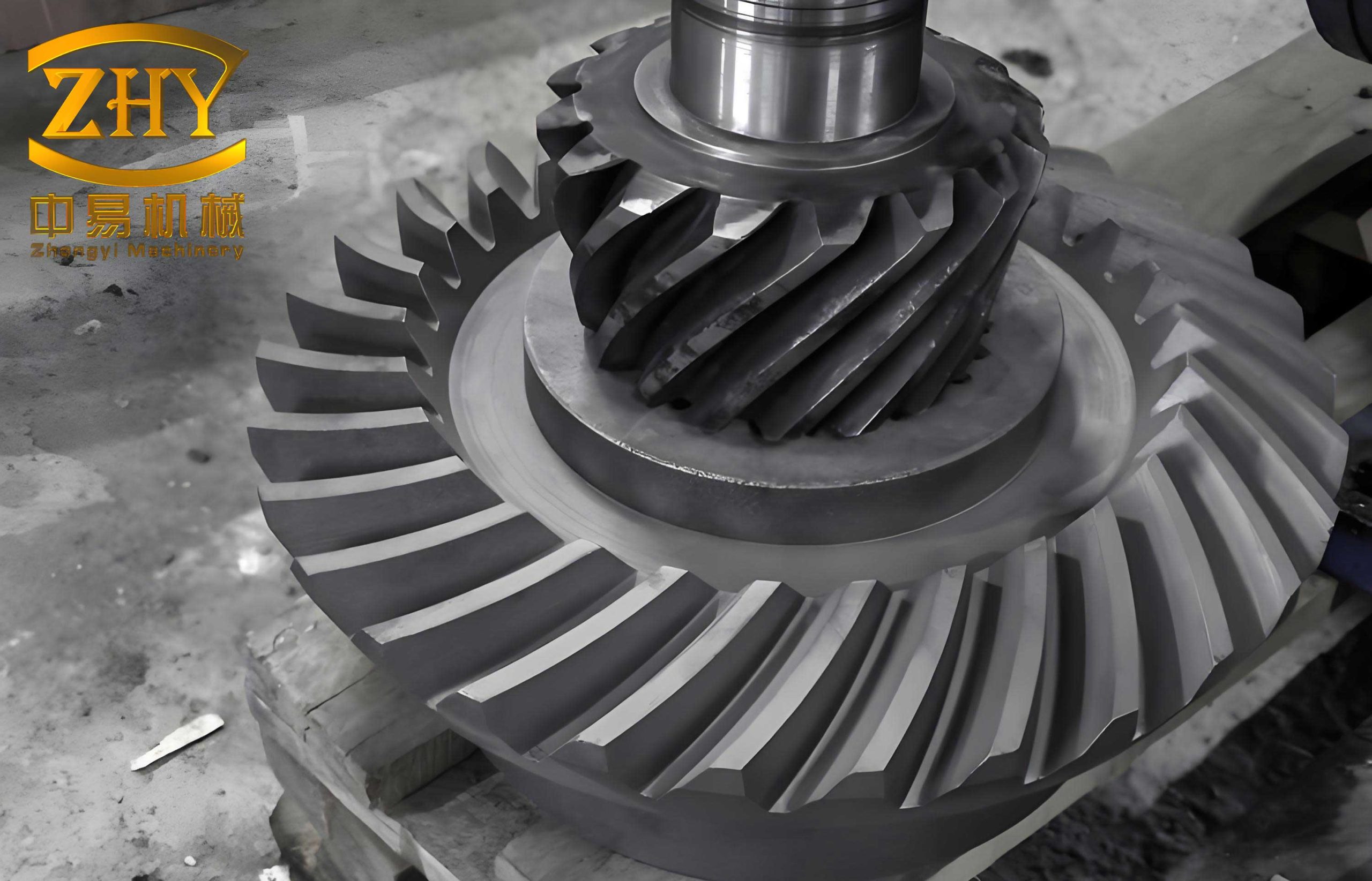
The seven-roll straightener’s drive system consists of three independent motor-reducer units, each driving a work roll (the top three rolls) via a pair of helical bevel gears. These gears, conforming to the Gleason system, offer advantages like high load capacity, low noise, and robustness. However, the harsh mill environment—filled with scale and dust—combined with an open-gear arrangement and marginal lubrication, severely challenged their durability. Post-installation, the helical bevel gear sets experienced persistent failures, necessitating near-monthly repairs and multiple gear replacements within a year, severely disrupting production.
Our analysis concluded that aside from operational conditions, fundamental design flaws were primary contributors:
- Inadequate Housing Strength: The reducer housings, fabricated from 20mm thick steel plate, were insufficient to resist the high axial thrust generated during lateral straightening.
- Improper Bearing Selection: The output shaft bearings could not effectively absorb the operational axial forces.
- Insufficient Gear Robustness: The original helical bevel gear design was relatively lightweight, leading to frequent tooth breakage.
In collaboration with the original manufacturer, we implemented a comprehensive redesign of the transmission system, with the helical bevel gear at its core.
2.1 Key Modifications to the Helical Bevel Gear System
The table below summarizes the critical parameter changes made to the helical bevel gear set to enhance its load-carrying capacity and reliability.
| Design Parameter | Original Design | Redesigned Specification | Purpose of Change | |
|---|---|---|---|---|
| Module (mm) | $$m = 8$$ | $$m = 10$$ | Increase tooth root bending strength and surface durability. | |
| Heat Treatment | Carburizing (Depth: ~0.8mm, Hardness: 58-62 HRC) | Carbonitriding (Depth: 0.6-0.9mm) | Easier to achieve consistent case depth; good wear and fatigue resistance. | |
| Pinion Design | Integrated Gear Shaft | Separate Gear with Tapered Bore | Simplifies heat treatment and allows for higher quality gear manufacturing. | |
| Lubrication | Single-Point Application | Multi-Point Spray System | Improves oil film coverage and cooling, reducing wear. |
Concurrently, the reducer housing plate thickness was increased, fasteners were added, and the output shaft bearing arrangement was upgraded to a combination bearing set capable of handling both radial and axial loads internally.
2.2 Force Analysis and Strength Verification for the Redesigned Helical Bevel Gear
To theoretically validate the new design, a detailed force analysis and contact strength verification were performed on the modified helical bevel gear pair. The following calculations follow the standard methodology for helical bevel gear rating.
Gear Parameters and Basic Calculations:
| Calculation Item | Formula / Value | Result / Parameter |
|---|---|---|
| Pinion Teeth, $$z_1$$ | Given | 19 |
| Gear Teeth, $$z_2$$ | Given | 39 |
| Module (at large end), $$m$$ | Given | 10 mm |
| Pinion Pitch Diameter, $$d_1$$ | $$d_1 = m \cdot z_1$$ | $$d_1 = 10 \times 19 = 190 \text{ mm}$$ |
| Gear Ratio, $$u$$ | $$u = z_2 / z_1$$ | $$u = 39 / 19 \approx 2.053$$ |
| Pinion Speed, $$n_1$$ | From Reducer Output | $$n_1 = 80 \text{ rpm}$$ |
| Motor Power, $$P$$ | Given | $$P = 22 \text{ kW}$$ |
| Nominal Torque at Pinion, $$T_1$$ | $$T_1 = 9.55 \times 10^6 \frac{P}{n_1}$$ | $$T_1 = 9.55 \times 10^6 \times \frac{22}{80} \approx 2.626 \times 10^6 \text{ N·mm}$$ |
| Tangential Force, $$F_t$$ | $$F_t = \frac{2 T_1}{d_1}$$ | $$F_t = \frac{2 \times 2.626 \times 10^6}{190} \approx 27,642 \text{ N}$$ |
Contact Stress Calculation (ISO 10300):
The fundamental formula for contact stress $$\sigma_H$$ is:
$$\sigma_H = Z_H Z_E Z_{\varepsilon} Z_K \sqrt{ \frac{F_t}{b d_1} \cdot \frac{u + 1}{u} }$$
Where:
$$Z_H$$ = Zone factor (accounts for tooth geometry)
$$Z_E$$ = Elasticity factor (accounts for material properties)
$$Z_{\varepsilon}$$ = Contact ratio factor
$$Z_K$$ = Bevel gear factor
$$b$$ = Face width (taken as 60 mm from design)
We calculate key factors:
1. Pitch Line Velocity, $$v$$:
$$v = \frac{\pi d_1 n_1}{60 \times 1000} = \frac{\pi \times 190 \times 80}{60000} \approx 0.796 \text{ m/s}$$
2. Application Factor, $$K_A$$: For rolling mill drives with moderate shock, $$K_A = 1.5$$.
3. Dynamic Factor, $$K_v$$: For $$v < 1 \text{ m/s}$$ and commercial gear quality, $$K_v \approx 1.05$$.
4. Load Distribution Factor, $$K_{H\beta}$$: For a supported shaft and face width $$\leq$$ 0.3 x cone distance, $$K_{H\beta} \approx 1.15$$.
5. Zone Factor, $$Z_H$$: For a spiral angle $$\beta_m = 35^\circ$$ and pressure angle $$\alpha_n = 20^\circ$$, $$Z_H \approx 2.3$$.
6. Elasticity Factor, $$Z_E$$: For steel gears, $$Z_E = 189.8 \sqrt{\text{N/mm}^2}$$.
7. Contact Ratio Factor, $$Z_{\varepsilon}$$: For reasonable overlap, $$Z_{\varepsilon} \approx 0.88$$.
8. Bevel Gear Factor, $$Z_K$$: For spiral bevel gears, $$Z_K \approx 0.8$$.
The equivalent tangential load for stress calculation is:
$$F_{t \text{eq}} = K_A \cdot K_v \cdot K_{H\beta} \cdot F_t = 1.5 \times 1.05 \times 1.15 \times 27,642 \approx 50,100 \text{ N}$$
Now, calculating the contact stress:
$$\sigma_H = 2.3 \times 189.8 \times 0.88 \times 0.8 \times \sqrt{ \frac{50100}{60 \times 190} \times \frac{2.053 + 1}{2.053} }$$
$$\sigma_H \approx 393.5 \times \sqrt{ \frac{50100}{11400} \times \frac{3.053}{2.053} } \approx 393.5 \times \sqrt{ 4.395 \times 1.487 }$$
$$\sigma_H \approx 393.5 \times \sqrt{ 6.537 } \approx 393.5 \times 2.557 \approx 1006 \text{ N/mm}^2$$
Permissible Contact Stress, $$\sigma_{HP}$$:
$$\sigma_{HP} = \frac{\sigma_{H \lim} \cdot Z_N \cdot Z_L \cdot Z_v \cdot Z_R \cdot Z_W \cdot Z_X}{S_{H \min}}$$
Where:
$$\sigma_{H \lim}$$ = Endurance limit for contact stress. For carbonitrided steel, a conservative value is $$\sigma_{H \lim} = 1300 \text{ N/mm}^2$$.
$$Z_N$$ = Life factor for $$10^7$$ cycles = 1.0.
$$Z_L, Z_v, Z_R$$ = Lubricant, velocity, and roughness factors. For initial grease lubrication and commercial finish, a combined derating of 0.85 is reasonable.
$$Z_W$$ = Work hardening factor = 1.0.
$$Z_X$$ = Size factor = 1.0 for module $$\leq$$ 10mm.
$$S_{H \min}$$ = Minimum safety factor = 1.2.
Thus:
$$\sigma_{HP} = \frac{1300 \times 1.0 \times 0.85}{1.2} \approx \frac{1105}{1.2} \approx 921 \text{ N/mm}^2$$
Safety Factor Check:
The calculated service contact stress ($$\sigma_H \approx 1006 \text{ N/mm}^2$$) is higher than the permissible stress ($$\sigma_{HP} \approx 921 \text{ N/mm}^2$$), indicating a nominal safety factor slightly below 1.0 based on this simplified model. However, this calculation uses conservative estimates for several factors (e.g., $$K_A$$, combined lubrication factors). In practice, the multi-point lubrication system improves $$Z_L, Z_R$$, and the actual dynamic loads may be lower. The core validation is the significant increase in the module from 8mm to 10mm. The contact stress is inversely proportional to the module. The ratio of stresses for the same load scales as:
$$\frac{\sigma_{H, \text{new}}}{\sigma_{H, \text{old}}} \propto \frac{1}{\sqrt{m_{\text{new}}}} \cdot \frac{\sqrt{m_{\text{old}}}}{1} = \sqrt{\frac{m_{\text{old}}}{m_{\text{new}}}} = \sqrt{\frac{8}{10}} \approx 0.894$$
This implies that, all else being equal, the contact stress in the new helical bevel gear with module 10 is about 89.4% of the stress in the old gear with module 8, representing an approximate 11% reduction in contact stress purely from the size increase. This reduction, combined with the material and lubrication improvements, brought the design into a safe operating margin, as proven by subsequent trouble-free operation for over 18 months post-refit.
Conclusion
The successful integration of the seven-roll straightening machine hinged on resolving two interconnected mechanical challenges: precise speed matching and the robust redesign of the critical power transmission element—the helical bevel gear drive. The speed adjustment, calculated based on work roll diameters and rotational speeds, created a harmonious pulling relationship between the two machines. The comprehensive redesign of the helical bevel gear system, featuring an increased module, improved heat treatment, better lubrication, and reinforced structural support, addressed the root causes of the frequent failures. The theoretical strength verification, while using conservative parameters, demonstrates the logical basis for the module increase and confirms that the new helical bevel gear design possesses a substantially higher load-carrying capacity than the original. This project underscores the importance of detailed mechanical analysis and tailored design modifications when deploying critical components like helical bevel gears in demanding industrial applications such as heavy-section rolling mills.