
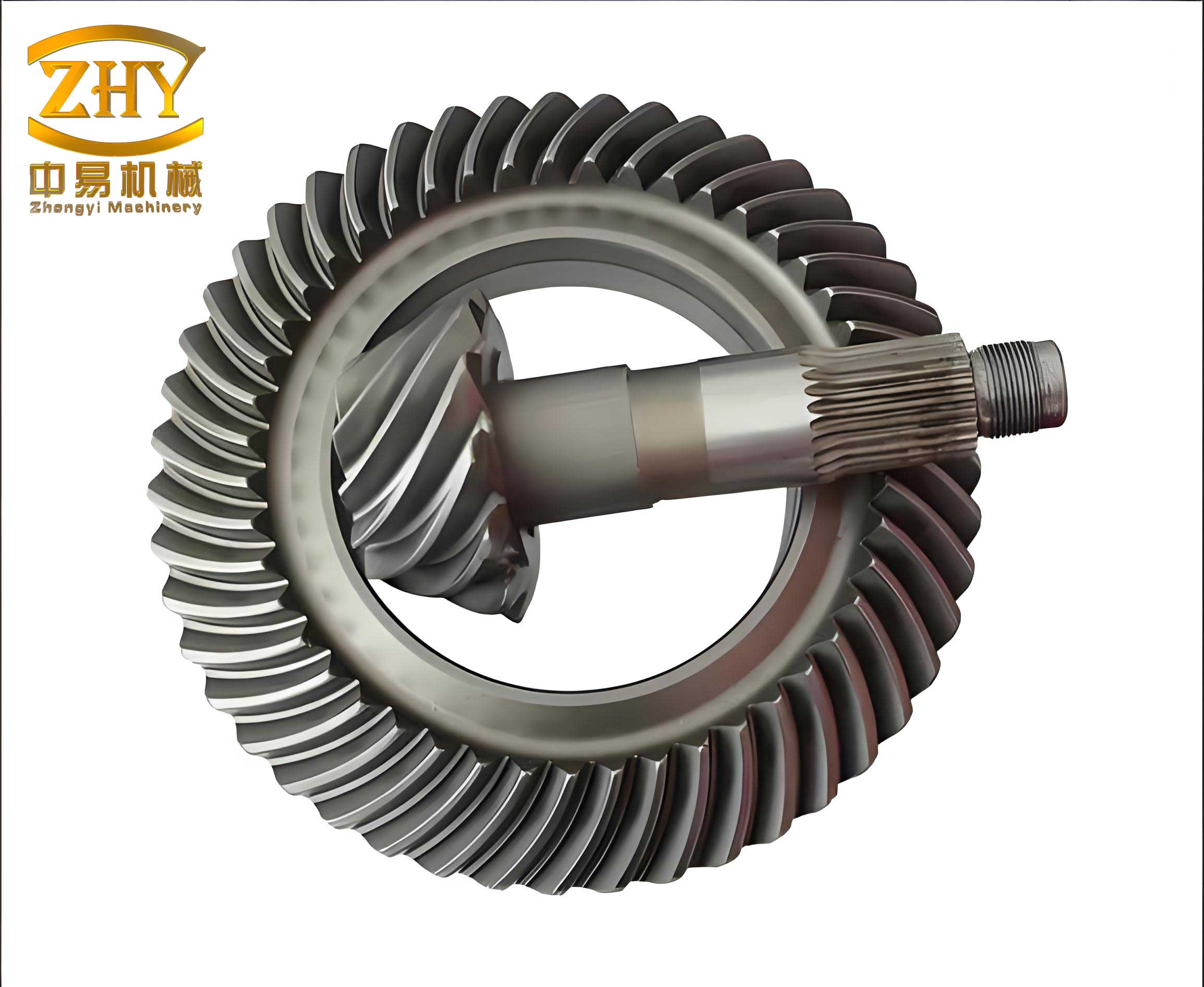
As a researcher who has been deeply involved in this field, I can attest that the helical bevel gear is a critical yet challenging component in automotive and tractor powertrains. Its complex geometry, requiring precise tooth form, spiral angle, and pressure angle, traditionally made it a production bottleneck. The conventional manufacturing route for these helical bevel gears depended on scarce, high-precision dedicated machine tools and a suite of cutting tools, grinding fixtures, and adjustment devices. Even with imported equipment, the gears had to be lapped in pairs, and their average service life was limited. The material of choice was typically a high-grade alloy steel like 20CrMnTi, placing this technology out of reach for most small and medium-sized factories, particularly local repair shops. This shortage often impacted the operational readiness of vehicles.
To address this urgent industrial and agricultural need and adhering to the principles of self-reliance and utilizing both modern and indigenous methods, our institute initiated laboratory experiments. Our goal was to pioneer an alternative: producing helical bevel gears using ductile iron and the precision casting process. This approach aimed to bypass the arduous machining of the tooth flanks, which is the core difficulty in helical bevel gear manufacturing.
We focused on systematically improving the comprehensive properties of ductile iron and the meshing accuracy and surface finish of the cast helical bevel gear. Initial trials and production runs for a specific vehicle model were conducted. These gears underwent rigorous road endurance tests according to standardized reliability protocols, as well as extended field trials in several vehicles. The results were promising, providing preliminary proof that the ductile iron precision casting route was viable for automotive helical bevel gears, leading to small-batch trial production. Success was also replicated in producing final drive gears for tractors, which withstood thousands of hours of field operation.
Driven by collaborative efforts, this technology has seen significant progress. The range of compatible vehicle models has expanded, quality has improved, and production volume has increased annually. Currently, numerous factories across the nation are engaged in trial production or full-scale manufacturing of these gears for various trucks and tractors. When produced with adequate meshing area and correct contact pattern positioning, the service life of these ductile iron helical bevel gears generally exceeds expectations for automobiles and demonstrates reliable longevity for tractors.
Experimental and Pilot Production Overview
1. Production Process
A. Casting Process: The helical bevel gears are cast using resin-coated quartz sand shell molds. The mold system employs two types of sand: a facing sand mixture of resin and fine quartz powder (approximately 0.1-0.3mm thick) and a backing sand of conventional molding sand. Solid or liquid phenolic resin is used as the binder, with an addition of 3-4% by weight. The mixture is mulled for 8-10 minutes until it reaches a non-sticky, moldable state. The molds are then dried at 180-200°C for 2-3 hours, resulting in a dark apricot or brown-yellow surface with good strength (dry tensile strength of 8-12 kg/cm²). For the pinion, a heated solid pattern is sometimes used to minimize distortion, requiring the addition of a catalyst like hexamine.
The fundamental challenge in precision casting a helical bevel gear lies in accounting for the solidification shrinkage of ductile iron. This shrinkage not only reduces the overall dimensions but also alters the effective spiral angle and pressure angle of the gear teeth. If a standard steel gear is used as the pattern, the cast gear’s contact pattern shifts significantly toward the toe and top of the tooth, drastically reducing the effective contact area.
The key to achieving high meshing accuracy is the design of the pattern gear, especially the pinion. By intentionally oversizing the pattern gear and modifying its nominal spiral and pressure angles, the distortion caused by casting shrinkage can be compensated for. The goal is to have the as-cast contact pattern of the helical bevel gear land close to the ideal position. The table below summarizes trials with different pattern gear modifications and their outcomes on the cast gear’s contact pattern.
| Pattern Gear Modification | Contact Pattern on Cast Gear (Drive Side) | Contact Pattern on Cast Gear (Coast Side) |
|---|---|---|
| Size increased, spiral & pressure angles unchanged | Shifts significantly toward toe & top; very small area. | Shifts significantly toward toe & top; very small area. |
| Size increased, spiral angle increased, pressure angle unchanged | Improves, shifts toward center but still biased. | Improves slightly but still biased. |
| Size increased, spiral & pressure angles both increased | Contact area expands significantly, position improves markedly. | Improves but may still be slightly high due to fixed cutter geometry for coast side. |
| Size and angles optimally adjusted based on detailed shrinkage analysis | Contact pattern approaches the ideal position and size. | Contact pattern approaches the ideal position and size. |
The primary objective of precision casting is to achieve the final tooth form without machining. Therefore, other functional surfaces like bores and shafts are cast with a machining allowance of 2-3mm. To ensure dimensional consistency, molds and core boxes use positive location stops. Melting in a medium-frequency furnace is preferred to ensure high-quality molten iron. Typical base iron and final treated ductile iron compositions are targeted as follows:
| Element | Base Iron (%) | Treated Ductile Iron (%) |
|---|---|---|
| C | 3.6-3.9 | 3.4-3.8 |
| Si | 1.8-2.2 | 2.4-2.8 |
| Mn | 0.6-0.9 | 0.6-0.9 |
| P | <0.1 | <0.1 |
| S | <0.03 | <0.03 |
| Mg (residual) | – | 0.03-0.05 |
B. Machining: Since only the tooth flanks are net-cast, machining is required for other features. Accurate location and clamping are critical to preserving the cast tooth geometry’s orientation.
For the pinion (driving helical bevel gear), the key step is establishing the center holes. One proven process involves: First, locating the pinion axially using the shaft journal as a datum to set its length. Then, clamping on the gear’s back cone, the front journal is turned and the small-end center hole is drilled. Subsequently, using the shaft journal again, the large-end face and cone are machined, and the large-end center hole is drilled. All subsequent operations (turning, splining, threading) use these two center holes as the datum, ensuring the gear teeth are concentric with the shaft axis.
For the ring gear (driven helical bevel gear), a three-ball pitch circle location method is highly effective. Three steel balls, fixed in a common plane, locate against the tooth root pitch circle. The gear is clamped against this plane, allowing the back face and pilot diameter to be machined first. The gear is then re-clamped using the pilot diameter to machine the bore and other features. Post-heat treatment, grinding operations also use the pitch circle for location. This method, based on the meshing surface itself, requires no manual alignment, ensures high accuracy, and improves efficiency.
C. Heat Treatment: To achieve optimal comprehensive properties, the machined helical bevel gears undergo austempering (isothermal quenching). This process yields a bainitic matrix, providing a favorable combination of strength, toughness, and wear resistance. Based on studies of the Continuous Cooling Transformation (CCT) behavior and the effects of composition, austenitizing temperature, isothermal temperature, and time, a standard heat treatment cycle was established.
Gears are heated in a high-temperature salt bath furnace (850-870°C) with a deoxidized bath to prevent decarburization. They are vertically suspended to minimize distortion. After soaking, they are rapidly quenched into a nitrite salt bath (280-320°C) for isothermal transformation, held for 60-90 minutes, and then cooled in a rust-preventive water wash. The resulting surface hardness is typically HRC 48-55. Despite being quenched freely, dimensional growth is minimal and predictable (e.g., ring gear OD increases by ~0.15mm, bore becomes slightly elliptical). Crucially, the change in contact pattern position is negligible. All gears treated this way meet the acceptance standards for hardened steel gears.
D. Electro-Spark Run-In (ESR): Even with an optimized pattern gear, the as-cast helical bevel gear may have minor surface imperfections or a contact pattern that requires final refinement. Electro-spark run-in serves as an effective precision finishing process. In this process, the gear pair is assembled in a housing with electrical insulation at the bearings. A pulsed power supply is connected to the gears via copper-graphite brushes. The gears are rotated in a bath of dielectric oil (viscosity adjusted for ambient temperature), and the spark erosion selectively removes minute amounts of metal from the contacting surfaces.
Typically, a run-in time of 15-20 minutes per side (drive and coast) significantly improves the contact area (e.g., from 30-40% to over 60%) and surface finish. To prevent the formation of a “step” on the tooth flank from single-position erosion, an adjustable fixture is used to vary the meshing backlash during the run-in cycle. This ensures uniform material removal across the active profile of the helical bevel gear. Final inspection checks for contact pattern position (preferably on the toe half), backlash (0.15-0.25mm with minimal variation), runout, and acceptable noise characteristics.
2. Production, Performance, and Characteristics
Field investigations covering hundreds of vehicles across several models have yielded significant insights into the performance of ductile iron helical bevel gears.
Material Performance: While laboratory tests show the bending fatigue strength of the ductile iron (40-45 kg/mm²) is lower than that of alloy steel, field data has not revealed any failures attributed to insufficient bending fatigue strength in the ductile iron gears. Failures due to impact-induced tooth breakage (typically on the ring gear) are extremely rare and occur in both material types. Service mileage for various vehicles has been substantial, demonstrating practical reliability.
Distinctive Characteristics of Ductile Iron Gears:
- Pitting Behavior: Surface pitting may initiate earlier compared to steel gears but propagates very slowly. The pits remain shallow. In many cases, the surface becomes smoother with continued use, and pitting may even appear to diminish. This is a key characteristic often misunderstood, leading to premature replacement.
- Noise and Wear: The graphite in ductile iron provides inherent damping. Therefore, at equivalent meshing accuracy, ductile iron helical bevel gears often operate more quietly than their steel counterparts. They exhibit an initial run-in wear (approx. 0.05mm) after which the wear rate decreases dramatically, becoming virtually immeasurable per service interval.
- Heat Treatment Response: The austempering process induces minimal and consistent distortion, allowing gears to meet tight geometric tolerances without complex quenching fixtures. The bainitic matrix, combined with graphite, provides adequate performance at hardness levels (HRC 48-52) that are easier to achieve consistently compared to the higher hardness often required for steel gears.
- Manufacturing Accessibility: The primary advantage is democratizing production. By eliminating the need for special gear-cutting machines and scarce alloy steel, this process enables small and medium-sized factories, especially repair shops, to produce these critical helical bevel gear components with relatively simple equipment, fostering local self-sufficiency.
3. Economic Impact
The economic benefits are clear. Substituting ductile iron for low-alloy steel saves a significant amount of strategic material per gear set. On a cost basis, the raw material for a ductile iron helical bevel gear is only about 30% of the cost for a steel gear. While pilot-scale machining costs may be higher due to manual setup, the elimination of the entire gear-cutting line (multiple expensive machines, tooling, and skilled labor) promises substantial savings in capital investment and operational cost at scale. The process is inherently flexible and adaptable to various gear designs without major retooling.
Methods for Enhancing the Precision of Cast Helical Bevel Gears
The core challenges in perfecting this technology revolve around precision: achieving consistent, high-quality meshing in the as-cast state. Key areas for improvement include:
1. Optimized Pattern Gear Design: This remains the most critical factor. Using a production steel gear as a pattern is insufficient. The pattern must be a purpose-designed “negative” of the desired final cast gear, incorporating precise oversize factors and angular corrections to compensate for solidification shrinkage. The required modification can be complex, as it involves non-uniform scaling. A simplified representation of the needed dimensional compensation along the tooth profile can be conceptualized with a scaling factor $k$ (where $k > 1$) and an angular correction $\Delta \beta$ for the spiral angle and $\Delta \alpha$ for the pressure angle. The relationship is not linear, but the pattern gear’s nominal dimensions $D_{pattern}$ and angles are derived from the target gear dimensions $D_{target}$:
$$ D_{pattern} \approx k \cdot D_{target} $$
$$ \beta_{pattern} = \beta_{target} + \Delta \beta $$
$$ \alpha_{pattern} = \alpha_{target} + \Delta \alpha $$
Determining the optimal values for $k$, $\Delta \beta$, and $\Delta \alpha$ requires empirical data from trial castings or sophisticated simulation of the casting and solidification process specific to the helical bevel gear geometry.
2. Advanced Molding Techniques: Manual resin-sand molding, where sand is packed into each tooth gap by hand, leads to inconsistent mold density and variable restraint on shrinkage, causing uneven tooth-to-tooth spacing and contact pattern variation. Transitioning to machine molding (e.g., pressure or blow molding) ensures uniform, high mold hardness. This improves the surface finish of the cast helical bevel gear teeth and promotes more consistent and predictable shrinkage, directly enhancing meshing accuracy and reducing variability.
3. Refined Gating and Feeding: The placement of ingates and the feeding system must be designed to ensure sequential solidification toward a riser and to minimize thermal gradients that can cause warpage. For a helical bevel gear, particularly the ring gear, multiple, symmetrically arranged ingates are essential to achieve uniform filling and cooling, reducing residual stresses that can distort the critical tooth geometry.
4. Consistent and Controlled Machining Datums: While the pitch-circle location method is effective, further standardization of machining fixtures and sequences is needed for high-volume production. Ensuring that every helical bevel gear is located from its functional meshing geometry (pitch cone) during all post-casting machining operations is paramount to preserving the cast tooth alignment.
In conclusion, the development of ductile iron precision-cast helical bevel gears represents a successful and pragmatic technological solution. It has proven its functional reliability in demanding field applications while offering significant advantages in terms of material savings, production accessibility, and economic efficiency. The performance of these gears, characterized by good wear resistance, damping, and a unique pitting behavior, is suitable for a wide range of vehicle applications. The continued focus must be on mastering and stabilizing the precision aspects—primarily through scientific pattern gear design, process automation, and rigorous quality control—to transition this promising technology from successful pilot production to robust, high-volume manufacturing. This will further solidify the role of ductile iron as a viable and valuable material for power transmission components like the helical bevel gear.