
In the field of vehicle braking technology, particularly for medium and small-sized vehicles operating under prolonged downhill conditions, conventional friction-based service brake systems face significant challenges. Continuous application leads to excessive wear, heat fade, and potential failure, compromising safety and operational economy. This necessitates the development of robust, reliable auxiliary braking systems. This article presents a comprehensive analysis and design exploration of a novel auxiliary retarder system. The core innovation lies in its primary reliance on a mechanical-hydraulic feedback mechanism, with electronic controls serving only a supplementary role, thereby ensuring fail-safe operation. The system intelligently converts rotational kinetic energy into hydraulic damping, providing continuous speed control.
The fundamental operational principle is based on a centrifugal governor mechanism directly linked to the vehicle’s driveline, typically the wheel motor or a driven shaft. As rotational speed increases, centrifugal forces act on weighted flyweights, causing them to pivot outward. This pivoting motion is mechanically translated into an axial displacement of a sleeve. This sleeve directly acts upon a spool valve, which is the heart of the hydraulic control circuit. The valve regulates the flow of hydraulic fluid from the system’s pump, effectively creating a variable orifice. This relationship can be expressed by the fundamental flow equation for an orifice:
$$ Q = C_d A \sqrt{\frac{2 \Delta P}{\rho}} $$
Where \( Q \) is the flow rate, \( C_d \) is the discharge coefficient, \( A \) is the orifice area (variable, controlled by the spool), \( \Delta P \) is the pressure differential across the orifice, and \( \rho \) is the fluid density. The regulated flow creates a back pressure within the hydraulic circuit connected to the wheel motor. This back pressure generates a resistive torque opposing the motor’s rotation. The braking torque \( T_b \) produced by the hydraulic motor can be described as:
$$ T_b = \frac{\Delta P \cdot D_m}{2\pi} $$
where \( D_m \) is the displacement of the hydraulic motor. Since \( \Delta P \) is a function of the restricted flow \( Q \), which is itself a function of the spool position \( x \) (controlled by speed \( \omega \)), we establish the core feedback loop: Speed ↑ → Flyweight displacement ↑ → Spool movement ↑ → Orifice area ↓ → Flow restriction ↑ → System Pressure ↑ → Braking Torque ↑ → Speed ↓.
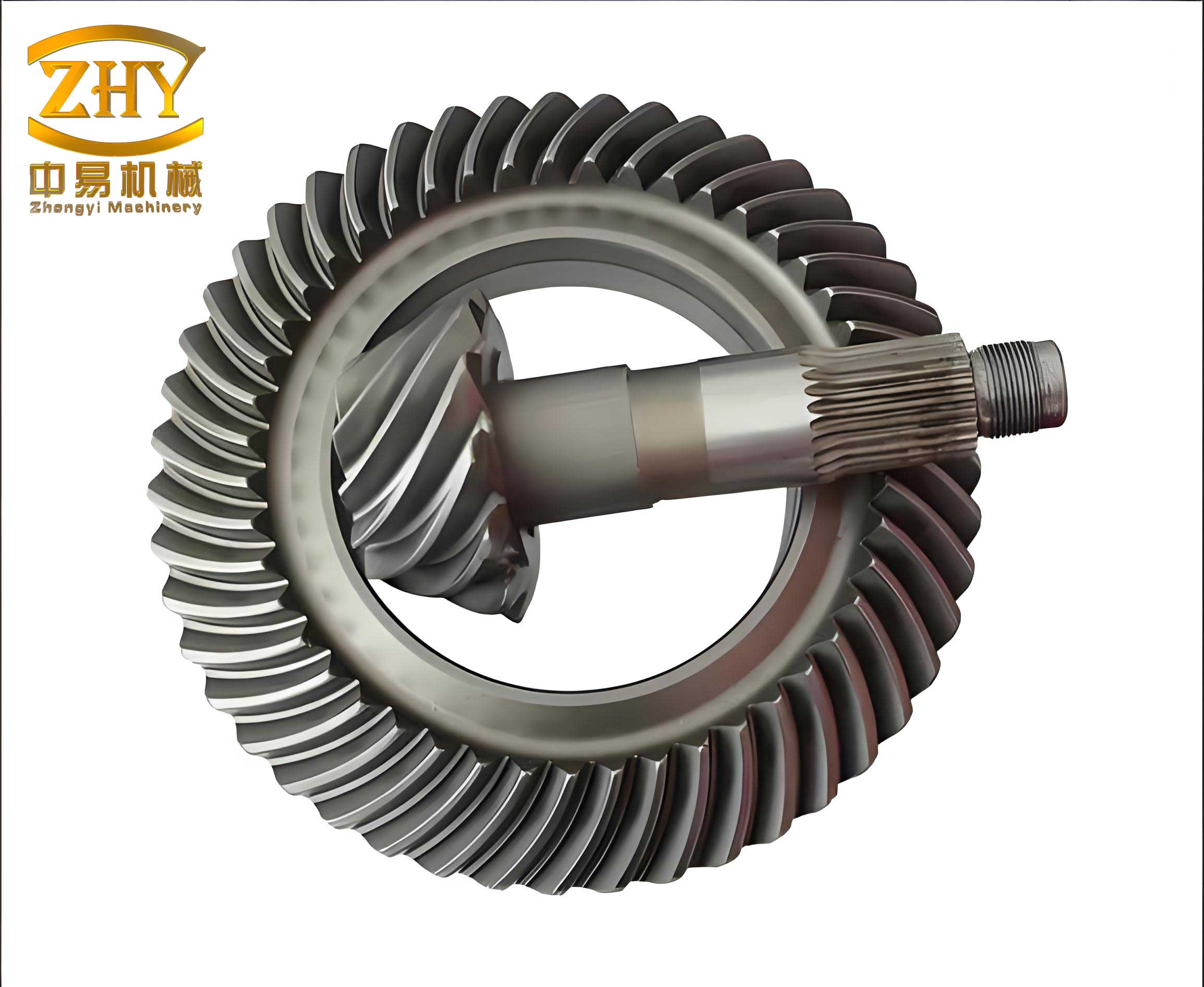
The integration of this retarder into a vehicle’s powertrain often involves a helical bevel gear set. A helical bevel gear assembly is crucial for transmitting power from the longitudinal driveline to the wheel axes, especially in applications requiring compact and efficient torque transfer at right angles. The high contact ratio and gradual engagement of a helical bevel gear reduce noise and increase load capacity, making it ideal for receiving input from the centrifugal governor mechanism and transmitting both drive and braking torques. The kinematic relationship at this stage is vital for system calibration.
The following table summarizes the primary components and their functions within the system:
| Component | Function | Key Characteristic |
|---|---|---|
| Centrifugal Governor | Senses rotational speed; converts it to mechanical displacement. | Weights, springs, and linkage determine the speed-displacement curve. |
| Spool Control Valve | Acts as a variable hydraulic orifice; controlled by governor displacement. | Includes critical fail-safe features like a permanent bleed orifice. |
| Hydraulic Pump/Motor | Serves as the actuator; converts fluid pressure into braking torque. | Displacement volume \(D_m\) is a key design parameter for torque scaling. |
| Helical Bevel Gear Set | Transmits power and braking reaction torque within the driveline. | Provides efficient, high-strength power transfer at 90 degrees. |
| Spring Preload Mechanism | Sets the initial response threshold and maximum spool travel limit. | Adjustable via screw; defines the system’s base calibration. |
The fail-safe feature is a paramount design achievement. Consider the scenario where electronic control is completely lost and vehicle speed becomes dangerously high. The flyweights will achieve maximum deflection, driving the sleeve to push the spool to its extreme position, virtually closing the main outflow port (B). To prevent a catastrophic system lock-up (zero flow leading to infinite pressure), the spool is engineered with a permanent, minute bleed orifice (e). This ensures a minimum sustainable flow \(Q_{min}\):
$$ Q_{min} = C_d A_e \sqrt{\frac{2 \Delta P_{max}}{\rho}} $$
where \( A_e \) is the fixed area of the bleed orifice. This small flow corresponds to a very low, “crawl” speed for the hydraulic motor and the vehicle, guaranteeing a safe ultimate speed limit under all conditions. A secondary throttle valve can be added downstream to fine-tune this minimum flow if required.
The dynamic response of the system is defined by the relationship between rotational speed (ω) and the spool valve displacement (x). This characteristic curve is primarily governed by the centrifugal force balance on the flyweights. The centrifugal force \(F_c\) is given by:
$$ F_c = m r \omega^2 $$
where \(m\) is the mass of the flyweight, \(r\) is the effective radius of rotation (a function of the swing angle θ), and ω is the angular velocity. This force is balanced by a preloaded spring force \(F_s = k (x_0 + x)\), where \(k\) is the spring constant and \(x_0\) is the pre-compression. The kinematic linkage converts angular displacement θ to linear displacement x. The resulting characteristic is non-linear but monotonic. As simulated, the spool travel increases progressively with system RPM, as shown in the conceptual curve below. This direct mechanical feedback ensures a predictable and immediate response to speed changes.
The performance of the system is highly dependent on the precise selection and matching of parameters. The following table outlines key design parameters and their influence on system behavior:
| Parameter | Symbol | Influence on System | Design Consideration |
|---|---|---|---|
| Flyweight Mass | \(m\) | Directly scales centrifugal force; affects sensitivity and response threshold. | Larger mass increases sensitivity but adds inertia. |
| Governor Spring Rate | \(k\) | Determines the speed at which the valve begins to actuate (preload) and the steepness of the response curve. | A softer spring yields earlier intervention; stiffer spring provides higher threshold. |
| Bleed Orifice Area | \(A_e\) | Sets the minimum guaranteed system flow and the ultimate safe speed under fault conditions. | Must be large enough to prevent overheating/pressure spikes but small enough for effective limiting. |
| Hydraulic Motor Displacement | \(D_m\) | Scales the braking torque generated for a given system pressure. | Chosen based on vehicle weight and desired maximum retarding power. |
| Helical Bevel Gear Ratio | \(i_{gb}\) | Modifies the speed signal seen by the governor relative to wheel speed and the torque applied to the driveline. | Optimized for packaging and to match the governor’s operational RPM range to vehicle speed. |
Integrating this retarder requires careful consideration of the powertrain architecture. The driveline, employing a robust helical bevel gear differential, receives the retarding torque from the hydraulic circuit. The efficiency and durability of the helical bevel gear directly impact the overall system efficiency, as power losses here translate to reduced braking effect and unnecessary heat generation. The gear design must account for both driving and braking torque loads. Furthermore, in systems where the governor is not mounted directly on the wheel hub, a helical bevel gear set might be used in the take-off mechanism to drive the governor assembly itself, ensuring accurate speed sensing from the main propshaft.
For analytical modeling, the system’s state can be described by differential equations. The equation of motion for the vehicle (simplified) is:
$$ I_{eq} \frac{d\omega}{dt} = T_{drive} – T_{b}(\omega) – T_{loss} $$
where \(I_{eq}\) is the equivalent inertia reflected to the retarder shaft, \(T_{drive}\) is the driving torque (e.g., from gravity on a slope), \(T_{loss}\) represents all frictional losses, and \(T_{b}(\omega)\) is the speed-dependent braking torque from our system. \(T_{b}(\omega)\) is the composite function linking speed to torque: \( \omega \rightarrow x(\omega) \rightarrow A(x) \rightarrow \Delta P(Q, A) \rightarrow T_b(\Delta P) \). This non-linear relationship defines the steady-state equilibrium speed for a given driving condition, where \(T_{drive} = T_b(\omega) + T_{loss}\).
A significant advantage of this design is its adaptability. By adjusting the spring preload (\(x_0\)) and the mechanical limits of spool travel, the system’s operational envelope can be tuned. For instance, a heavier vehicle would require a calibration yielding higher braking torque at a given speed. This is achieved by adjusting the linkage or spring to allow greater spool movement (smaller orifice area \(A\)) for the same centrifugal force, thereby generating higher \(\Delta P\) and \(T_b\). The graph of valve spool travel versus system speed is the master calibration curve for the entire system.
From a reliability and safety perspective, the system offers a multi-layered approach. The primary layer is the purely mechanical-hydraulic feedback loop, which is always active. The secondary, optional layer is electronic monitoring and control, which could modulate the spring preload via an actuator or introduce an auxiliary bypass valve for finer control under normal conditions. However, the failure of this electronic layer does not disable the core braking function; it merely reverts to the fully mechanical safety mode governed by the bleed orifice. This deterministic fail-safe behavior is superior to systems relying solely on active electronic controls.
In comparison to other auxiliary braking systems like engine brakes or electromagnetic retarders, this centrifugal-hydraulic system offers unique benefits, particularly for medium-duty applications. The following table provides a high-level comparison:
| System Type | Principle | Advantages | Disadvantages |
|---|---|---|---|
| Centrifugal-Hydraulic (This Design) | Mechanical speed sensing with hydraulic torque generation. | Inherently fail-safe, no external power needed for core function, durable, cost-effective for mid-range vehicles. | Power dissipation limited by hydraulic cooling, adds hydraulic system complexity. |
| Electromagnetic Retarder | Eddy currents induced in a rotor by an electromagnet. | Very high power dissipation capacity, no physical contact, fast response. | Requires significant electrical power, heavy, high cost, dependent on electrical system. |
| Engine Brake (Jake Brake) | Alters engine valve timing to create negative work. | Very powerful, uses existing engine components. | Only for internal combustion engines, very noisy, complex to implement. |
| Exhaust Brake | Restricts engine exhaust flow. | Simple, inexpensive. | Less powerful than other methods, increases exhaust system back-pressure and temperature. |
Future development and optimization of this system involve several key areas. The parametric matching of the pump’s flow capacity to the control valve’s characteristic and the hydraulic motor’s displacement is critical for maximizing energy absorption without causing excessive pressure spikes. Computational Fluid Dynamics (CFD) analysis can optimize the spool valve port geometry to achieve desired flow-pressure curves and reduce cavitation. Furthermore, material science plays a role in enhancing the longevity of the centrifugal governor’s pivoting joints and the helical bevel gear teeth, which are subject to cyclical loads during braking events. Advanced lubricants for the helical bevel gear set can reduce losses and improve overall efficiency.
In conclusion, the mechanically-controlled centrifugal hydraulic retarder represents a robust, reliable, and intelligent solution for auxiliary vehicle braking. Its elegance lies in the direct, physics-based feedback loop where speed automatically modulates braking effort. The incorporation of a durable power transmission component like a helical bevel gear ensures efficient torque transfer within the system. By guaranteeing functionality even in the total absence of electrical power or electronic controls through its ingenious fail-safe bleed orifice, it meets the highest standards of functional safety. This design philosophy, prioritizing mechanical certainty with electronic augmentation, offers a compelling and cost-effective option for enhancing safety and reducing wear on primary service brakes in a wide range of automotive and industrial transportation applications.