
Helical bevel gears for automobile rear axle drive systems represent a critical yet challenging component in automotive parts production. The conventional manufacturing route for these helical bevel gears demands high-quality alloy steel and an exceptionally complex machining process. Specifically, the tooth-cutting operation alone requires a battery of five expensive imported Gleason machine tools, accompanied by a complete set of supporting equipment for tool grinding, sharpening, and machine adjustment. This high barrier to entry makes it nearly impossible for small and medium-sized factories, especially general automotive repair shops, to produce these helical bevel gears independently. The resulting supply shortage has frequently disrupted normal vehicle transportation. To address this challenge and embody the principles of self-reliance and the simultaneous development of both indigenous and advanced methods, we initiated a research and development program. Our goal was to trial the production of these helical bevel gears using ductile iron (specifically, rare-earth alloyed ductile iron) and the precision investment casting process.
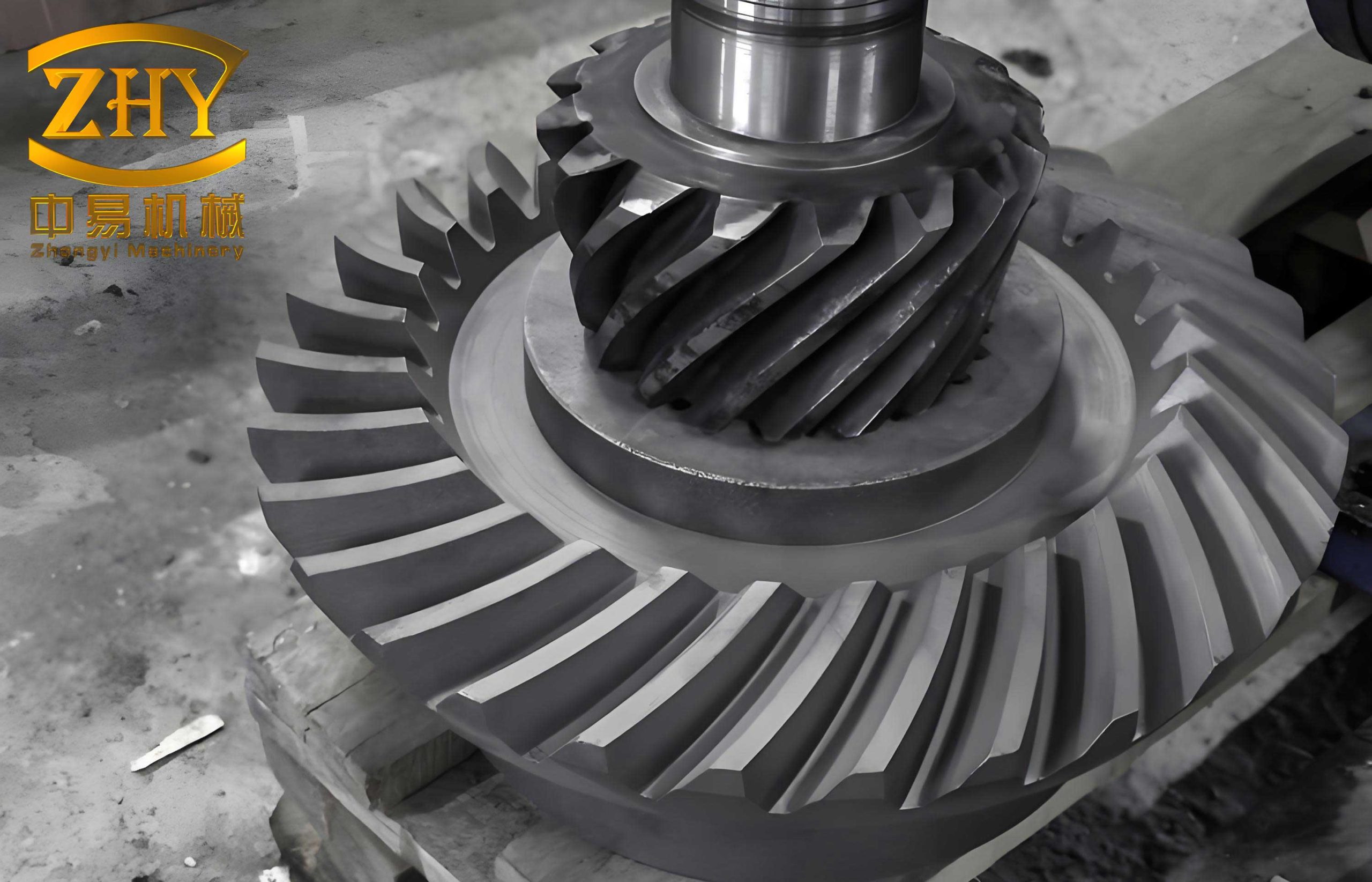
The finished product, a set of investment-cast ductile iron drive and driven helical bevel gears, is shown below. This particular gear set is characterized by a high tooth count, small module, and a large spiral angle, making it one of the more difficult types to cast successfully.
Our initial trials yielded promising results. To stabilize and improve the quality of these cast helical bevel gears, we conducted systematic investigations over the past two years. This included measuring the isothermal transformation curves (TTT diagrams), critical points, and martensite start (Ms) points of the rare-earth alloyed ductile iron. Based on this data, we established an appropriate heat treatment process to enhance the comprehensive material properties. We also experimented with model gears featuring different, pre-corrected mesh contact patterns and implemented an electro-spark (EDM) run-in process. These efforts significantly improved both the appearance and internal quality of the gears, enhancing tooth surface finish and meshing accuracy. Most importantly, through rigorous road endurance tests on two vehicles and practical use trials on six others, the ductile iron helical bevel gears were subjected to and withstood demanding service conditions.
The results conclusively demonstrate that substituting rare-earth alloyed ductile iron and the investment casting process for the traditional alloy steel and gear milling operations in producing automobile drive and driven helical bevel gears is a viable and successful approach. It provides a new pathway for small and medium-sized factories to manufacture this critical component. However, our findings are preliminary and not yet exhaustive. Guided by the imperative to conscientiously sum up experience, we present this summary to consolidate achievements, identify problems, and guide future experimental work towards faster and better outcomes.
Gear Parameters:
Drive Gear: Teeth (Z1) = 6, Spiral Direction = Left, Spiral Angle (β) = 50°, Mean Pressure Angle (α) = 22°30′, Module (m) = 6.35 mm, Whole Depth (h) = 13.2 mm, Addendum (ha) = 6.35 mm.
Driven Gear: Teeth (Z2) = 37.
I. Performance Testing of Ductile Iron Gears
A. Comparative Material Property Tests
Conventional steel helical bevel gears undergo case carburizing, quenching, and low-temperature tempering to achieve a favorable combination of strength, hardness, and toughness. We conducted comparative tests to determine if austempered ductile iron (ADI) could attain similar properties. Specimens were prepared and tested as follows:
- Steel Specimens: Machined from the splined shaft of a drive gear (~Φ28 mm diameter).
- Ductile Iron Specimens: Taken from wedge-shaped test blocks with a wall thickness of 25 mm.
- Heat Treatment: Steel specimens were carburized, quenched, and tempered alongside production gears. Ductile iron was austempered: heated at 880°C for 30 minutes, then isothermally quenched at 280°C for 1.5 hours.
- Test Methods: Impact tests used 10x10x55 mm un-notched specimens. Bending fatigue tests used Φ7.52 mm un-notched specimens.
The results of the material strength tests are summarized in the table below.
| Material | Tensile Strength (kgf/mm²) | Impact Value (kgf·m/cm²) | Bending Fatigue Limit (kgf/mm²) | Surface Hardness (HRC) |
|---|---|---|---|---|
| Alloy Steel (20CrMnTi) | 112.0 | 8.5 | 50.0 | 58-62 |
| Rare-earth Ductile Iron (Austempered) | 138.6 | 9.8 | 40.0 | 48-55 |
The results indicate that the rare-earth alloyed ductile iron exhibits higher tensile strength and impact value than the steel. However, its bending fatigue strength and surface hardness are lower.
B. Comparative Static Torsion Strength Tests
To compare the structural strength of the gear teeth themselves, we conducted static torsion tests on complete gear sets. The test setup involved mounting the gear set in a housing, locking the driven gear, and applying a torsional load to the drive gear’s splined shaft via a lever arm. The applied torque (T) was calculated from the force (F) on the lever:
$$ T = F \times L $$
where L is the horizontal distance from the force application point to the shaft center (1 meter). Deformation was measured as the vertical displacement of a fixed point on the lever arm. The test was conducted until the splined shaft underwent plastic deformation.
The test results are presented in the table below and the accompanying torque-deformation curve.
| Gear Set ID | Material | Torque at Onset of Plastic Deformation (kgf·m) | Final Torque (kgf·m) | Ultimate Deformation (mm) |
|---|---|---|---|---|
| No. 1 | Steel | 90 | 160 | ~13 |
| No. 2 | Ductile Iron | 65 | 180 | ~25 |
| No. 3 | Ductile Iron | 95 | 195 | ~22 |
| No. 4 | Ductile Iron | 110 | 190 | ~18 |
The static torsion tests revealed that the weak point of this gear set design is not the gear teeth but the splined shaft of the drive gear. Therefore, the torque at which the spline begins to deform plastically is used to compare static strength. The rare-earth ductile iron showed a static torsional strength slightly higher (approximately 95-110 kgf·m) than that of the alloy steel (90 kgf·m). This value is about 4.5 times the maximum working torque of the vehicle (20-22 kgf·m). Metallographic examination of tested gears indicated that variations in the as-cast matrix structure (e.g., small amounts of ferrite, amount of phosphide eutectic, fineness of bainite needles, presence of martensite/retained austenite) did not significantly affect the static torsional strength of the helical bevel gears.
II. Road Endurance Trials
While material tests indicated high static strength but lower dynamic (fatigue) performance and hardness for ductile iron, component behavior under actual service conditions is the ultimate test. We therefore conducted intensified road trials on vehicles equipped with the ductile iron helical bevel gears. The test conditions are summarized below.
| Vehicle ID | Test Conditions & Items | Total Test Distance (km) | Notes |
|---|---|---|---|
| A | Mountain roads (full trailer load), sandy beach runs. Gears tested for 34,000 km total. | 34,000 | For faster run-in, old gears were installed on the front axle and new cast gears on the rear axle during initial beach tests. |
| B | Gravel roads (overload), tank proving ground, sandy beach runs (full load). | 10,000 | Same run-in procedure as Vehicle A. |
The wear and surface condition of the gear teeth were monitored throughout the trials. Key observations are cataloged in the following table.
| Vehicle ID | Distance (km) | Road Characteristics | Tooth Surface Condition | Wear/Backlash Notes |
|---|---|---|---|---|
| A | 2,500 | Mixed conditions | Small pits appeared on drive gear dedendum. | Initial wear ~0.10 mm. Backlash increased from 0.15 mm to 0.30 mm. |
| 5,000 | Mixed conditions | Pits slightly enlarged and deepened (~0.15 mm). | Wear stable. Surface brightened. | |
| 10,000 | Mixed conditions | Little change in pits. | – | |
| 20,000 | Mixed conditions (incl. tank track) | Surface smoother. Pits nearly disappeared. | Backlash adjusted down to 0.15-0.20 mm. | |
| 34,000 | Mixed conditions (incl. beach) | Surface smooth. Isolated large pits on 1-2 drive gear teeth. | No measurable wear after initial run-in. | |
| B | 10,000 | Intensified gravel, beach, tank track | Surface smooth and bright. | Performance satisfactory under severe duty. |
The road trial results demonstrate several key points. Firstly, after a total distance of over 40,000 km under severe conditions, no tooth breakage occurred. This confirms that the austempered ductile iron helical bevel gears possess sufficient bending fatigue strength and impact load capacity for demanding automotive use. Secondly, an initial wear period (approximately 0.10-0.20 mm over 2,500-5,000 km) was observed, after which wear essentially ceased, and the surfaces became very smooth. This indicates good wear resistance despite lower surface hardness, potentially related to initial surface decarburization from heat treatment and imperfect initial contact pattern. Thirdly, surface pitting appeared early (around 2,500 km), primarily on the drive gear. However, unlike typical steel gear pitting, these pits were mostly small and shallow, developed very slowly, and often became smoother or disappeared with further running. We hypothesize that the graphite nodules in the ductile iron, while potentially initiating pits under high contact stress (due to lower hardness), also act as crack arresters, preventing propagation. As the surface work-hardens and the contact pattern improves, the pitting damage becomes non-progressive. This fundamental difference in failure mode suggests ductile iron helical bevel gears may not require the same high surface hardness as their steel counterparts.
III. Production Process for Investment-Cast Ductile Iron Gears
A. Casting Process
The helical bevel gears were produced using a resin-coated sand (shell molding) investment casting process. A facing sand mixture of resin and quartz flour (approx. 1.5-2.0 mm thick) was backed with ordinary molding sand. The mold assembly was designed with alignment pins to ensure dimensional accuracy between cope and drag. Only the gear teeth were cast to net shape; other functional surfaces (bores, mounting faces) were provided with a machining allowance of 1.5-2.0 mm.
The most critical aspect was designing the pattern gear (the master used to make the mold). Initial trials used a standard, finished steel gear as the pattern. However, solidification shrinkage of ductile iron not only reduced overall size but also altered the effective spiral and pressure angles, causing the contact pattern to shift unfavorably towards the toe and top of the tooth. To compensate, we experimented with pattern gears that were intentionally oversized and had modified geometry. The results of different pattern gear strategies are summarized below.
| Pattern Gear Strategy | Resulting Contact Pattern (% of tooth face) | Advantages | Disadvantages | Applicability |
|---|---|---|---|---|
| Standard gear (no scaling) | 20-30% | Uses existing part; quick start. | Poor contact; requires extensive manual or EDM correction. | Single-piece repair. |
| Linear scale-up (1.8%) | ~40% | Easier to machine pattern; better contact. | Still requires EDM run-in for final fit. | Small batch. |
| Scale-up (1.8%) + Spiral/Pressure angle correction | 50-60% (near target) | Good contact pattern; may eliminate need for EDM. | Requires dedicated, precisely machined pattern gear. | Batch production. |
Based on these trials, the final production method employed a corrected and scaled pattern gear for the drive gear, and a simply scaled pattern for the driven gear. The molten iron was melted in a basic three-phase electric arc furnace. Base iron composition was targeted at: C: 3.6-3.9%, Si: 1.8-2.2%, Mn: <0.5%, P: <0.1%, S: <0.03%. Treatment was performed in a ladle using a rare-earth magnesium alloy (1.3-1.5% addition) for nodularization, followed by inoculation with 75% FeSi (0.6-0.8% addition). Pouring temperature was maintained at 1320-1350°C.
B. Machining Process
Since the teeth are cast, precise location of the gear blank for machining other features is paramount. The key step for the drive gear is drilling the center holes. The process involves:
- Chucking the gear roughly by the shaft and using the cast gear cone back face as a reference to true it on a lathe (runout < 0.05 mm).
- Facing the back and drilling the first center hole.
- Remounting the gear by clamping the teeth in a dedicated fixture, using the rough-turned shaft section for alignment (runout <±0.03 mm), then cutting the shaft to length and drilling the second center hole.
For the driven gear, the process involves chucking by the riser/gating stub, machining primary reference surfaces (the back face and the O.D. near the bore), and then using these surfaces as the datum for all subsequent operations, including riser removal.
C. Heat Treatment
All gears undergo austempering to achieve a bainitic microstructure (austempered ductile iron – ADI) with optimal combination of strength and toughness. To define the process, we systematically determined the isothermal transformation diagram for the alloy. A representative curve can be described by critical temperatures and transformation kinetics. The austenitizing temperature ($T_\gamma$) and isothermal temperature ($T_{iso}$) are key parameters:
$$ T_\gamma = 860 – 880\,^\circ\mathrm{C} $$
$$ T_{iso} = 280 – 300\,^\circ\mathrm{C} $$
The final heat treatment cycle established is: Heat to $880 \pm 10\,^\circ\mathrm{C}$, hold for 30 minutes (austenitizing); rapidly quench into a $280 \pm 10\,^\circ\mathrm{C}$ nitrate-nitrite salt bath; hold isothermally for 1.5 hours; air cool. Heating is done in a salt bath furnace with protective atmosphere to minimize surface decarburization. This process results in a primarily lower bainite matrix with hardness of HRC 48-55. Dimensional changes post-heat treatment are predictable (e.g., driven gear O.D. expands ~0.20 mm) and all gears remained within the factory’s acceptance standards for ground steel gears.
D. Electro-Spark (EDM) Run-in
Even with optimized pattern gears, a final precision finishing of the tooth flanks is beneficial to improve surface finish, remove minor casting scale/inclusions, and perfect the contact pattern. We employ a short-duration electro-spark run-in process. The gear set is installed in its housing (electrically insulated), connected to a pulsed power supply, and run under no load immersed in heavy gear oil. The electrical discharge selectively erodes microscopic high points, improving conformity. A typical two-stage process is used:
- Roughing: Higher voltage (80-100V), lower frequency (400-600 Hz) to rapidly improve contact area.
- Finishing: Lower voltage (40-50V), higher frequency (20-25 kHz) to improve surface finish.
Total run-in time is only 5-10 minutes per gear set. This process is highly effective as a final matching operation for investment-cast helical bevel gears.
IV. Economic Impact
The successful implementation of investment-cast ductile iron helical bevel gears offers significant economic advantages, especially for manufacturers lacking specialized gear-cutting equipment.
| Factor | Traditional Steel & Milling | Ductile Iron & Investment Casting | Saving per Gear Set | Annual Saving (Est. 50k sets) |
|---|---|---|---|---|
| Material | Alloy Steel (20CrMnTi), ~2.2 kg/set | Ductile Iron, ~2.2 kg/set | ~5.60 CNY (Material cost only) | 280,000 CNY |
| Key Process | 5 specialized Gleason machines + tooling | Eliminated (Teeth cast to shape) | High capital & tooling cost avoided | Major capital saving |
| Strategic Benefit | Dependent on imported machines & alloy steel | Enables local production with basic facilities | Independence from supply chain bottlenecks | Secured component supply |
The material saving alone is substantial, translating to thousands of tons of alloy steel saved annually. While our trial-stage machining costs were not optimized, the elimination of the complex and capital-intensive gear milling operation guarantees a lower final production cost in volume manufacturing.
V. Proposed Draft Specification for Cast Gear Blanks
Based on our experimental findings, we propose the following basic requirements for ductile iron investment-cast helical bevel gear blanks as a foundation for a formal specification:
- Chemical Composition (Final): C: 3.4-3.8%, Si: 2.4-2.8%, Mn: <0.5%, P: <0.1%, S: <0.03%, Mg (residual): >0.03%.
- As-Cast Microstructure:
- Graphite: >80% spheroidal, size grade 5-7 (small to medium).
- Matrix: Predominantly pearlitic/ferritic, acceptable for subsequent austempering.
- Carbides & Phosphide Eutectic: <3% combined.
- Cast Surface Quality (Tooth Flanks): Must be clean, with sharp profile definition. No cold shuts, mistuns, or gross porosity. After cleaning, no sand holes or slag inclusions are permitted. Minor adhering sand or hard spots must be removable by light stoning.
- Heat Treatment: Austempering to a bainitic matrix with a hardness of HRC 48-55 is mandatory for finished gears.
In conclusion, our work over the past two years has validated the technical and economic feasibility of producing automotive helical bevel gears from austempered ductile iron via the investment casting route. This approach provides a practical solution for small and medium-sized enterprises to manufacture this critical component, overcoming barriers related to specialized equipment and alloy steel supply. While further systematic studies on full-scale fatigue testing, large-scale durability, and process refinement are warranted, the core finding is unequivocal: ductile iron is a competent and innovative material for manufacturing high-performance helical bevel gears.