
In my years of experience within automotive repair and manufacturing, I have consistently encountered the formidable challenges associated with producing high-precision helical bevel gears. The absence of dedicated cutting machinery often led to protracted lead times, excessive material waste, and gears that failed to meet stringent performance criteria. This predicament, however, served as a catalyst for innovation. Driven by necessity, my team and I embarked on developing and refining a hot rolling process for helical bevel gears. This transformative approach has not only dramatically enhanced production efficiency but has also yielded helical bevel gears with exceptional accuracy, rivaling Grade 8 standards. Helical bevel gears are indispensable components in powertrain systems, particularly in automotive differentials, where they facilitate smooth power transmission between intersecting shafts at high angles. This article, drawn from my firsthand involvement, will comprehensively explore the design principles, the hot rolling methodology, the underlying engineering mechanics, and the performance validation of helical bevel gears produced through this innovative technique. I will incorporate mathematical models, process data tables, and technical analyses to provide a thorough exposition on advancing helical bevel gear technology.
The fundamental geometry of helical bevel gears is considerably more complex than that of parallel-axis gears. Their design involves a confluence of parameters that dictate meshing action, load capacity, and operational noise. A deep understanding of these parameters is paramount for any manufacturing process. Key specifications include the diametral pitch (or module), number of teeth, pressure angle, pitch cone angle, spiral angle, and face width. For instance, a common helical bevel gear set for an automotive application might feature a driving pinion with 11 teeth and a driven gear with 41 teeth, operating at a shaft angle of 90 degrees. The teeth are curved and oblique relative to the cone element, introducing a gradual engagement that reduces impact loads and noise—a hallmark advantage of helical bevel gears over straight bevel gears. The contact pattern and load distribution across the tooth flank are critical performance indicators, heavily influenced by the precise control of the spiral angle and tooth profile. To visualize the intricate, three-dimensional form of these components, consider the following representation:
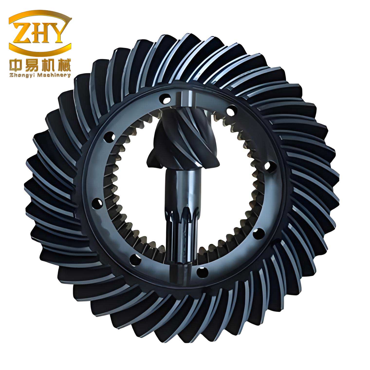
This image captures the sophisticated architecture of helical bevel gears, showcasing the helical teeth winding around the conical pitch surface. The manufacturing of such geometries to micron-level tolerances has traditionally been the domain of specialized gear-cutting machines like spiral bevel gear generators. The quest for a more efficient method led us to explore plastic forming, specifically hot rolling.
The hot rolling process for helical bevel gears is a net-shape forming operation that plastically deforms a heated gear blank against a precision master gear, often called a rolling die or轧轮. Our experimental setup involved retrofitting a standard lathe. We mounted a dedicated fixture onto the tool post to securely hold the pre-machined gear blank. A hardened and ground helical bevel gear, serving as the master, was firmly clamped in the lathe’s spindle chuck. The critical process parameters we meticulously controlled included the blank heating temperature, the rotational speed of the master gear, the infeed pressure, and the cooling regime. The gear blank, typically forged from alloy steel such as SAE 8620, was heated uniformly to a temperature within the austenitic region, ranging from 900°C to 1000°C, using oxy-acetylene torches. At this temperature, the material’s yield strength drops significantly, allowing substantial plastic deformation without fracture. The heated blank was then brought into pressured contact with the rotating master gear. The master gear rotated at a slow, controlled speed of 4 to 6 revolutions per minute. As the blank rolled against the master, its surface material flowed into the cavities between the master gear’s teeth, progressively forming the conjugate tooth geometry on the blank. Continuous water cooling was applied to the master gear to prevent its own temperature rise and potential loss of dimensional accuracy. The entire forming and subsequent finishing (or sizing) operation was typically completed in one to two hours per helical bevel gear pinion.
The mechanical and metallurgical principles governing this process are profound. The stress-strain relationship during hot working can be described by a simplified flow curve model:
$$ \sigma = K \epsilon^n $$
where $\sigma$ is the flow stress, $\epsilon$ is the true strain, $K$ is the strength coefficient, and $n$ is the strain-hardening exponent. For the steel used in helical bevel gears at rolling temperatures, $n$ is typically low, indicating minimal work hardening, which is ideal for extensive deformation. The total effective strain imparted to the gear tooth region is a complex function of the gear geometry and rolling pass schedule. Furthermore, the process induces beneficial grain flow lines that follow the contour of the gear teeth, unlike the cut teeth which interrupt the material’s grain structure. This results in helical bevel gears with potentially superior fatigue strength, particularly in the tooth root fillet region, a critical area for bending fatigue failure.
To quantify the geometric specifications of the helical bevel gears we produced, the following table enumerates the key design parameters for the active pinion gear:
| Design Parameter | Symbol | Value |
|---|---|---|
| Diametral Pitch | $P_d$ | 10 in$^{-1}$ |
| Number of Teeth | $N$ | 11 |
| Pressure Angle | $\phi$ | 20° |
| Pitch Cone Angle | $\Gamma$ | 26° 34′ |
| Shaft Angle | $\Sigma$ | 90° |
| Whole Depth of Tooth | $h_t$ | 0.216 in |
| Mean Spiral Angle | $\beta_m$ | 35° |
| Hand of Spiral | – | Left |
| Mating Gear Teeth | $N_{mate}$ | 41 |
These parameters are interrelated through fundamental gear geometry equations. The pitch diameter $D_p$ of the pinion is calculated as $D_p = N / P_d = 1.1$ inches. The cone distance $A$, a crucial reference dimension, is given by $A = D_p / (2 \sin \Gamma)$. For reliable operation, the design of helical bevel gears must also ensure an appropriate contact ratio. The transverse contact ratio ($m_p$) and the face contact ratio ($m_F$) combine to give the total contact ratio ($m_t$), which for helical bevel gears should significantly exceed 1.0 to ensure smooth, continuous power transmission. An approximate formula for the transverse contact ratio is:
$$ m_p \approx \frac{\sqrt{(r_{a1}^2 – r_{b1}^2)} + \sqrt{(r_{a2}^2 – r_{b2}^2)} – A \sin \phi_t}{\pi m_t \cos \beta_m} $$
where $r_a$ is the addendum radius, $r_b$ is the base radius, $m_t$ is the transverse module, and $\phi_t$ is the transverse pressure angle. The complexity of these calculations underscores the precision required in both the design and the manufacturing replication of helical bevel gears.
Our experimental hot rolling process required careful optimization of several operational variables. The table below summarizes the range and optimal values we established through iterative trials for producing durable helical bevel gears:
| Process Variable | Operational Range | Optimized Setting | Remarks |
|---|---|---|---|
| Blank Heating Temperature | 900°C – 1000°C | 950°C ± 10°C | Ensures full austenitization and optimal plasticity |
| Master Gear Rotational Speed | 4 – 6 rpm | 5 rpm | Balances forming time and heat generation |
| Forming Pressure / Infeed | Controlled by tool post feed | Incremental, multi-pass | Prevents overloading and ensures complete fill |
| Total Process Time | 1.0 – 2.0 hours | ~1.5 hours | Includes heating, rough rolling, and finish sizing |
| Master Gear Cooling | Water spray | Continuous, low-flow | Maintains master gear dimensional stability |
| Post-rolling Cooling | Still air | Controlled in vermiculite | To prevent excessive oxidation and decarburization |
The success of forming accurate helical bevel gears via hot rolling is contingent upon the synchronization of these parameters. Deviations, especially in temperature, can lead to defects such as underfill, laps, or excessive grain growth, compromising the integrity of the helical bevel gears.
From a strength perspective, helical bevel gears must withstand significant bending and contact stresses. The Lewis bending stress formula provides a foundational analysis, though more advanced methods like AGMA standards are used for design. The modified Lewis equation for a gear tooth is:
$$ \sigma_b = \frac{W_t}{F m_n Y} $$
where $\sigma_b$ is the bending stress, $W_t$ is the transmitted tangential load at the pitch circle, $F$ is the face width, $m_n$ is the normal module ($m_n = m_t / \cos \beta$), and $Y$ is the Lewis form factor, which depends on the tooth shape and pressure angle. For helical bevel gears, the load is distributed over several teeth due to the overlap ratio, and the effective face width is considered. More critically, the surface durability, governed by contact (Hertzian) stress, is vital for pitting resistance. The maximum contact stress $\sigma_H$ between two meshing teeth can be estimated by:
$$ \sigma_H = C_p \sqrt{ \frac{W_t}{F D_p I} \cdot \frac{\cos \beta}{\sin \phi_t} \cdot \frac{i+1}{i} } $$
where $C_p$ is the elastic coefficient, $I$ is the geometry factor for surface durability, and $i$ is the gear ratio ($i = N_{gear} / N_{pinion}$). The production of helical bevel gears via hot rolling can positively influence these strength parameters. The improved grain flow and potential for a work-hardened surface layer can enhance both bending fatigue limit and contact fatigue life compared to gears where the tooth profile is cut across the grain structure.
Quality assurance for hot-rolled helical bevel gears involves comprehensive inspection. We employed gear roll testers to check for proper tooth contact pattern under light load, coordinate measuring machines (CMMs) for critical dimensions like pitch deviation and runout, and surface roughness testers. The helical bevel gears produced through our optimized hot rolling process consistently exhibited lead and profile errors within the limits for Grade 8 accuracy per AGMA standards. The surface finish on the tooth flanks was notably smooth, often in the range of 1.0 to 1.6 micrometers Ra, reducing the need for subsequent grinding in many applications.
The practical validation of these helical bevel gears was conducted in real-world service. Multiple pinion gears manufactured by our hot rolling method were installed as the driving helical bevel gears in the differentials of White 3000-series trucks operating in demanding mountainous terrain, often under full load with trailers. Performance monitoring over distances exceeding 10,000 kilometers revealed no incidence of premature wear, pitting, tooth breakage, or abnormal noise. This field performance convincingly demonstrated that hot-rolled helical bevel gears could meet and even exceed the durability requirements of heavy-duty automotive applications. The success hinged on the gears’ ability to maintain proper lubrication film and distribute loads evenly across the tooth face, a testament to the geometric accuracy achieved.
When contrasting hot rolling with traditional manufacturing routes for helical bevel gears, several advantages become clear. Conventional methods like face milling, face hobbing, or generating grinding involve sequential material removal, which is time-consuming, generates swarf, and may compromise material integrity. Hot rolling, as a forming process, is inherently more material-efficient, with near-zero waste. It also integrates the tooth forming and finishing stages, reducing total processing time. However, the method demands high-quality, wear-resistant master gears and precise control over thermal conditions. For high-volume production, dedicated hot rolling machines with synchronized axes, induction heating stations, and automated handling would be necessary to achieve consistent output of precision helical bevel gears.
Looking forward, the potential for hot rolling helical bevel gears extends beyond automotive repairs into sectors like aerospace, marine, and industrial machinery. Research avenues include exploring isothermal rolling for more temperature-sensitive materials like titanium alloys, implementing finite element analysis (FEA) to simulate the metal flow and predict defects, and developing advanced tooling coatings to extend master gear life. The integration of in-process sensing and adaptive control could further stabilize the process, ensuring every helical bevel gear meets exacting specifications. The fundamental equation governing heat transfer during the process, crucial for predicting temperature gradients, is Fourier’s law, and its application in this context is complex due to the moving interface and phase changes.
In summary, based on my extensive hands-on experience, the hot rolling process represents a significant and viable innovation in the manufacturing of helical bevel gears. It addresses the dual challenges of efficiency and precision, particularly in environments lacking traditional gear-cutting infrastructure. The helical bevel gears produced are not only geometrically accurate but also benefit from favorable metallurgical characteristics imparted by the thermomechanical processing. While challenges remain in scaling up and fully automating the process, the foundational success demonstrated in our trials provides a compelling blueprint for the future. As the demand for high-performance, cost-effective power transmission components grows, advanced forming techniques like hot rolling are poised to play an increasingly central role in the production of critical components like helical bevel gears, driving forward the capabilities of modern mechanical systems.