
Through experimental analysis, this study investigates the influence of key control parameters on the contact pattern characteristics during the machining of hypoid gears for an automotive rear axle. The focused parameters are the contact pattern length factor (λ) and the tool pressure angle correction (α_p). The findings provide crucial guidance for adjusting machine settings to achieve optimal contact pattern position and shape, which are critical for the performance and durability of hyperboloid gear sets.
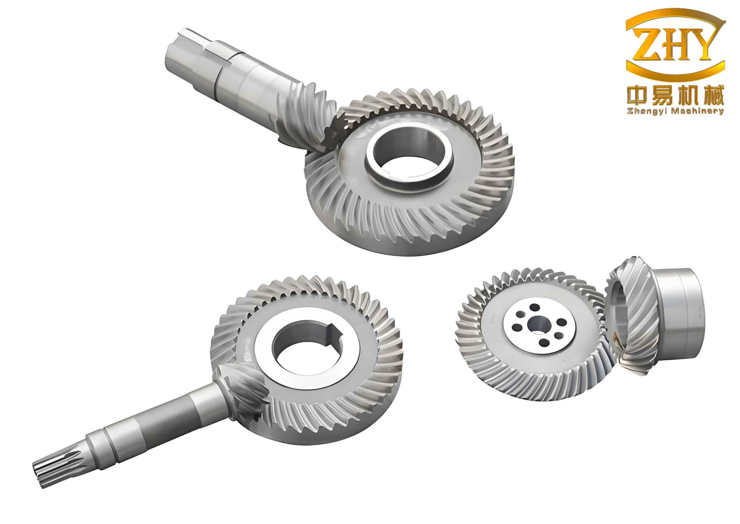
Introduction
The Tilted Head Half-Generating (THHG) method, also known as the Formate method for the gear and generating for the pinion, is specifically designed for machining hypoid gears where the gear blank cone angle exceeds 50°. In this process, the gear (or larger wheel) is cut using a form-cutting method, while the pinion (or smaller wheel) is generated. A distinctive feature is the tilting of the cutter head by a normal rake angle, hence the name. The Gleason system for hyperboloid gear design provides calculation cards with several control parameters. Understanding the influence of these parameters, particularly on the resulting tooth contact pattern, is paramount for efficient production setup and minimizing trial cuts. The primary control parameters include the contact pattern length factor (λ), the pinion root angle correction (ΔE), the tool pressure angle (α_p), and the effective generating gear pitch line length (L_p’). This work builds upon foundational studies and employs a “single-factor” experimental approach. By altering only one control parameter at a time while keeping others at their initial values, we systematically isolate and define the effects of parameters λ and α_p on the contact pattern formation in a specific hyperboloid gear application.
Experimental Methodology and Machine Setup
Test Subject and Baseline Data
The test subject was a hypoid gear pair from an automotive rear axle. The primary design and geometric data for this hyperboloid gear set, such as number of teeth, gear ratio, shaft offset, pitch angles, and module, were used as the baseline for all calculations. The gear was pre-machined using the formate method. All pinion cutting trials were conducted on a specialized hypoid gear generator. The meshing and contact pattern inspection were performed on a universal rolling tester. The machine adjustment data for each trial was calculated using a computer program based on the formulas from the relevant Gleason calculation system for the THHG method.
Experimental Plan
In the THHG method, the gear is finish-cut by a formate process, and the pinion is generated by a process that includes a tilted cutter head. Among the four main control parameters, the variation of λ directly influences the calculated tool tip radius. In contrast, changes to α_p do not affect the tool tip radius. Therefore, the experimental sequence was established as follows:
- First, conduct trials by varying λ. The target was to achieve a contact pattern length approximating λ times the full face width. An optimal λ value was selected, which also fixed the corresponding tool tip radius for all subsequent experiments.
- Subsequently, conduct trials by varying α_p while keeping λ and the corresponding tool tip radius constant.
The contact patterns were recorded using the conventional method of applying a thin layer of marking compound (e.g., Prussian blue) to the gear teeth, rolling the gear set under light load, and transferring the pattern from the pinion to the gear using transparent tape. This provided a clear imprint for analysis.
| Parameter Symbol | Parameter Name | Primary Influence | Note |
|---|---|---|---|
| λ | Contact Pattern Length Factor | Theoretical length of the contact zone relative to face width. | Affects calculated tool tip radius. |
| ΔE | Pinion Root Angle Correction | Fine-tunes the pinion root geometry. | Not varied in this specific test series. |
| α_p | Tool Pressure Angle | Influences the local tooth curvature and contact path position. | Primary variable for contact path shift. |
| L_p’ | Effective Generating Gear Pitch Line Length | Scales the generating motion. | Fundamental for machine kinematics. |
Results, Analysis, and Mathematical Modeling
The imprinted contact patterns from the gear’s convex and concave flanks under different parameter settings were analyzed. The core observations are summarized and interpreted below.
Analysis of Parameter λ (Contact Pattern Length Factor)
Parameter λ is defined as the desired ratio of the contact zone length to the total face width under light load conditions. The experimental results confirmed a strong correlation: the actual length of the contact pattern increased proportionally with an increase in λ. For instance, with λ set to 0.5, the contact pattern occupied approximately half of the face width. However, it was observed that the actual printed contact length consistently exceeded the theoretical value (λ * Face Width). When λ was set to 0.4, the pattern already covered nearly 50% of the face width.
This discrepancy can be explained by understanding the nature of the contact pattern. The parameter λ theoretically governs the projection length of the instantaneous contact line along the face width direction. The contact pattern, however, is the accumulated imprint of all instantaneous contact lines throughout the entire mesh cycle. These instantaneous lines are not necessarily perpendicular to the face width and their orientation and effective length change during meshing. Therefore, the final composite pattern is longer than the projection of any single line. The relationship can be conceptually modeled. Let the face width coordinate be $w$, and the contact line at a roll angle $\phi$ be described by its end points $w_1(\phi)$ and $w_2(\phi)$. The theoretical λ is related to the maximum range of these endpoints:
$$
\lambda_{theory} \propto \frac{\max_{\phi}(|w_1(\phi) – w_2(\phi)|)}{W}
$$
where $W$ is the total face width. The actual pattern length $L_{actual}$ is the total span covered by the union of all lines:
$$
L_{actual} = \frac{\max_{\phi}(w_2(\phi)) – \min_{\phi}(w_1(\phi))}{W}
$$
Clearly, $L_{actual} \geq \lambda_{theory}$. Furthermore, the rolling test condition itself, including the thickness of the marking compound and the applied load, affects the apparent size of the pattern. Based on the analysis and industrial practice, a λ value of approximately 0.5 is recommended as optimal to achieve a practical contact pattern length covering about 50-60% of the face width for this type of hyperboloid gear.
| λ Value | Theoretical Length (% of Face Width) | Observed Pattern Length (Approx. % of Face Width) | Pattern Characteristic |
|---|---|---|---|
| 0.3 | 30% | ~40% | Short, centrally located. |
| 0.4 | 40% | ~50% | Moderate length, good centering. |
| 0.5 | 50% | ~60-65% | Long, sensitive to alignment errors. |
| 0.6 | 60% | ~70-75% | Very long, prone to run-off at ends. |
Analysis of Parameter α_p (Tool Pressure Angle)
The tool pressure angle α_p is a critical parameter for controlling the position of the contact path across the face width of the hyperboloid gear. The experimental results demonstrated a consistent and predictable trend:
- On the Gear Convex Side: As α_p increases, the contact pattern shifts towards the toe (outer end) of the gear tooth.
- On the Gear Concave Side: As α_p increases, the contact pattern shifts towards the heel (inner end) of the gear tooth.
This behavior is due to the change in the local tooth curvature induced by modifying the cutting tool’s pressure angle. The shift in contact path can be modeled by considering the effect on the equivalent crown gear. Changing α_p alters the transverse pressure angle at the point of generation, which modifies the curvature relationship between the pinion and gear tooth surfaces. The direction of the shift is governed by the hand of the gear and the direction of the offset. The sensitivity was most pronounced within the typical adjustment range specified in the calculation system (often ±1.5° from the nominal). This parameter serves as the primary control for moving the contact pattern along the face width without significantly altering its length or shape curvature, making it essential for fine-tuning the assembly and load-bearing characteristics of the hyperboloid gear set.
The relationship can be approximated by a linear correction factor. If Δα_p is the change in tool pressure angle from nominal, and Δw is the resulting shift of the contact pattern centroid (as a fraction of face width), then:
$$
\Delta w \approx C \cdot \Delta \alpha_p
$$
where $C$ is a sensitivity coefficient whose sign depends on the flank (convex or concave) and the gear hand. For the tested gear set, $C$ was positive for the convex flank and negative for the concave flank.
| Change in α_p (Δα_p) | Gear Convex Flank Pattern Shift | Gear Concave Flank Pattern Shift | Primary Use Case |
|---|---|---|---|
| Increase (+) | Towards Toe | Towards Heel | Correct for pattern too far towards heel/concave-toe. |
| Decrease (-) | Towards Heel | Towards Toe | Correct for pattern too far towards toe/concave-heel. |
| No Change (0) | Central (Baseline) | Central (Baseline) | Nominal design position. |
Synthesis of Parameter Interactions
While this study used a single-factor method, it is important to note that in practice, parameters interact. For example, a change in λ (and thus tool tip radius) can slightly affect the local pressure angle of the cut. However, for the purpose of initial machine setup and corrective adjustment, the parameters can be treated as quasi-independent controls:
- λ (and tool radius): Used to set the approximate length of the contact pattern.
- α_p: Used to adjust the position of the contact pattern along the face width on both flanks.
- ΔE and L_p’: Used for other corrections like root clearance and overall scale of generation.
The mathematical model for the tooth surface $ \mathbf{r}(u, v; \lambda, \alpha_p) $ generated by the THHG method is complex, involving the kinematics of the tilted head and the generating roll. The control parameters directly enter these kinematic equations, modifying the family of tool positions and thus the envelope surface. The sensitivity analysis conducted here effectively measures the partial derivatives of the contact pattern metrics (length L, centroid position w_c) with respect to these parameters:
$$
\frac{\partial L}{\partial \lambda} > 0, \quad \frac{\partial w_{c}^{convex}}{\partial \alpha_p} > 0, \quad \frac{\partial w_{c}^{concave}}{\partial \alpha_p} < 0
$$
These signs confirm the observed experimental trends.
Conclusions
Based on the computational analysis and systematic experimental trials, the following conclusions are drawn regarding the manufacturing of hyperboloid gear pairs using the Tilted Head Half-Generating method:
- The THHG method, while distinct from similar processes for spiral bevel gears, utilizes a coherent and well-defined set of control parameters (λ, α_p, etc.) that align with established calculation systems. This allows for a simplified and standardized approach to cut-data calculation.
- The contact pattern length factor λ has a direct and predictable effect on the extent of the contact zone. An optimal value of λ ≈ 0.5 is recommended to achieve a practical contact pattern covering roughly half to sixty percent of the face width, accounting for the difference between theoretical instantaneous contact length and the accumulated pattern from the full mesh cycle.
- The tool pressure angle α_p is the primary control parameter for shifting the contact pattern along the face width. Increasing α_p moves the pattern toward the toe on the convex flank and toward the heel on the concave flank, providing a powerful and essential tool for correcting mispositioned contact.
- The “single-factor” experimental approach successfully isolated the effects of these key parameters. The understanding of these influence laws significantly enhances the ability to control final product quality, reduces the number of required trial cuts and associated scrap rates, and strengthens the practical utility of the THHG method in high-volume production of hyperboloid gear sets for automotive and other precision applications.
Future work could involve a full factorial design of experiments to quantify interaction effects between parameters and to develop a more comprehensive predictive model for contact pattern geometry as a function of all machine setup variables for the hyperboloid gear.