
In modern mechanical transmission systems, the contact fatigue failure of gears, such as micro-pitting, pitting, and spalling, poses a critical bottleneck for enhancing power density and reliability. The spur and pinion gear pairs, widely used in industrial applications, are particularly susceptible to these failures under high-load conditions. Therefore, developing accurate predictive models for contact fatigue risk is essential. This study focuses on carburized and quenched spur and pinion gears, aiming to establish a coupled mathematical model that integrates gradient material properties with multiaxial stress analysis. By leveraging explicit analytical solutions and discrete numerical methods, we address singular integral contact problems and evaluate the influence of key parameters on fatigue risk. The goal is to provide a foundation for designing high-performance spur and pinion gear systems with improved durability.
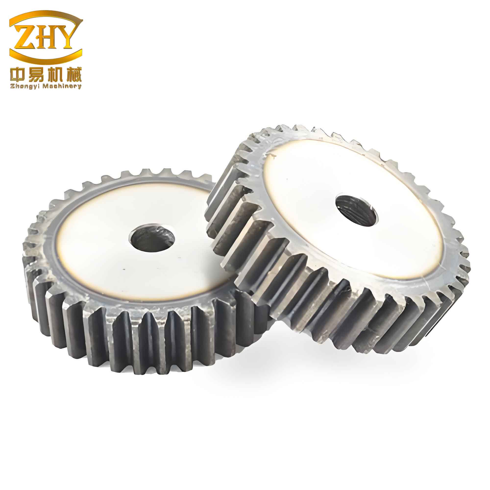
The contact fatigue behavior of spur and pinion gears is governed by complex interactions between surface stresses and material strength gradients. After carburizing and quenching, the gear teeth develop a hardened surface layer with varying hardness and residual stress profiles. These gradients significantly affect the load-bearing capacity and fatigue life. Traditional standards like ISO 6336 and GB/T 3480 provide methods for calculating contact stress and material strength, but they often overlook the detailed physical mechanisms of gradient effects. Thus, this research delves into the correlation between modified layer characteristics and mechanical responses during meshing. We propose a risk prediction model based on the Dang Van multiaxial fatigue criterion, incorporating hardness and residual stress gradients. The model is validated through analytical and numerical simulations, offering insights into failure mechanisms for spur and pinion gear applications.
Gear Meshing Contact Model
The meshing process of spur and pinion gears can be simplified using equivalent cylindrical contact theory. For a gear pair with a contact ratio between 1 and 2, the teeth experience alternating single and double contact along the line of action. At any meshing point, the curvature radii and contact parameters are derived from involute geometry and Hertzian elastic contact theory. The contact semi-width and nominal contact area relate to the pressure angle, as expressed below:
$$F = \frac{9549 P_0}{n R_{pm} \cos \alpha_{pm}}$$
$$b = \sqrt{\frac{4F}{\pi B} \cdot \frac{\rho_{pm} \rho_{qm}}{\rho_{pm} + \rho_{qm}} \cdot \left( \frac{1 – \nu_p^2}{E_p} + \frac{1 – \nu_q^2}{E_q} \right)}$$
$$\rho_{pm} = \frac{m z_p \cos \alpha \tan \alpha_{pm}}{2}$$
$$\rho_{qm} = \frac{m z_q \cos \alpha \tan \alpha_{qm}}{2}$$
Here, \(F\) is the load, \(P_0\) is the power, \(n\) is the rotational speed, \(R_{pm}\) is the radius at the contact point of the driving gear, \(\alpha_{pm}\) and \(\alpha_{qm}\) are the meshing angles, \(b\) is the contact semi-width, \(B\) is the face width, \(\rho_{pm}\) and \(\rho_{qm}\) are the curvature radii, \(\nu_p\) and \(E_p\) are Poisson’s ratio and elastic modulus for the driving gear, \(\nu_q\) and \(E_q\) are for the driven gear, \(m\) is the module, \(\alpha\) is the pressure angle, and \(z_p\) and \(z_q\) are the tooth numbers. For spur and pinion gears made of the same material, \(\nu_p = \nu_q\) and \(E_p = E_q\).
The elastic half-plane contact model is employed to analyze stress components within the gear tooth. Under combined normal and tangential loads, the stresses at any point \((x, z)\) are given by singular integrals:
$$\sigma_x = -\frac{2z}{\pi} \int_{x_1}^{x_2} \frac{p(t)(x-t)^2}{[(x-t)^2 + z^2]^2} dt – \frac{2}{\pi} \int_{x_1}^{x_2} \frac{q(t)(x-t)^3}{[(x-t)^2 + z^2]^2} dt$$
$$\sigma_z = -\frac{2z^3}{\pi} \int_{x_1}^{x_2} \frac{p(t)}{[(x-t)^2 + z^2]^2} dt – \frac{2z^2}{\pi} \int_{x_1}^{x_2} \frac{q(t)(x-t)}{[(x-t)^2 + z^2]^2} dt$$
$$\tau_{xz} = -\frac{2z^2}{\pi} \int_{x_1}^{x_2} \frac{p(t)(x-t)}{[(x-t)^2 + z^2]^2} dt – \frac{2z}{\pi} \int_{x_1}^{x_2} \frac{q(t)(x-t)^2}{[(x-t)^2 + z^2]^2} dt$$
where \(p(t)\) and \(q(t)\) are normal and tangential distributed loads, respectively. Solving these integrals analytically is challenging for complex load distributions, so we adopt a discrete numerical approach using rectangular micro-elements. Each element carries uniform loads, and the stress contributions are summed. For a rectangular normal load \(p_j\) over a width, the stress components are:
$$\sigma_{xp} = -\frac{p}{\pi} \left[ \arctan \frac{s – x}{z} + \arctan \frac{s + x}{z} – \frac{z(s + x)}{r_1^2} + \frac{z(x – s)}{r_2^2} \right]$$
$$\sigma_{zp} = -\frac{p}{\pi} \left[ \arctan \frac{s – x}{z} + \arctan \frac{s + x}{z} + \frac{z(s + x)}{r_1^2} – \frac{z(x – s)}{r_2^2} \right]$$
$$\tau_{xzp} = -\frac{z^2 p}{\pi} \left( \frac{1}{r_1^2} – \frac{1}{r_2^2} \right)$$
with \(r_1^2 = (s – x)^2 + z^2\) and \(r_2^2 = (s + x)^2 + z^2\). Similarly, for tangential load \(q_j\):
$$\sigma_{xq} = -\frac{q}{\pi} \left( \frac{z^2}{r_2^2} – \frac{z^2}{r_1^2} + 2 \ln \frac{r_2}{r_1} \right)$$
$$\sigma_{zq} = -\frac{z^2 q}{\pi} \left( \frac{1}{r_1^2} – \frac{1}{r_2^2} \right)$$
$$\tau_{xzq} = -\frac{q}{\pi} \left[ \arctan \frac{s – x}{z} + \arctan \frac{s + x}{z} – \frac{z(s + x)}{r_1^2} + \frac{z(x – s)}{r_2^2} \right]$$
By discretizing the load into \(n\) elements, the total stress at point \(i\) is:
$$\sigma_{xi} = \sum_{j=1}^{n} \left( T_{p,j-i} p_j + T_{q,j-i} q_j \right)$$
where \(T_{p,j-i}\) and \(T_{q,j-i}\) are influence functions derived from the above equations. This method efficiently computes stress fields for spur and pinion gear contacts.
Performance Gradients and Fatigue Parameters
Carburizing and quenching introduce gradients in hardness and residual stress, which are crucial for contact fatigue resistance. For spur and pinion gears, the hardness distribution from surface to core is modeled using a piecewise quadratic function based on the effective case hardening depth (DCHD):
$$HV(z) =
\begin{cases}
a_a z^2 + b_a z + c_a, & 0 \leq z < \text{DCHD} \\
a_b z^2 + b_b z + c_b, & \text{DCHD} \leq z < z_{\text{core}} \\
HV_{\text{core}}, & z_{\text{core}} < z
\end{cases}$$
where \(HV_{\text{core}}\) is the core hardness, and coefficients are determined from experimental data. This gradient enhances surface strength while maintaining core toughness. The residual stress gradient, primarily compressive near the surface, is described by a sigmoidal model:
$$\sigma_{\text{RS}}(z) = \sigma_D + \frac{\sigma_z – \sigma_D}{1 + e^{-k(z + \delta)}}$$
Here, \(\sigma_D\) is the maximum compressive residual stress, \(\sigma_z\) is the tensile stress, and \(k\) and \(\delta\) are fitting parameters. These gradients directly influence material strength parameters used in fatigue analysis.
To convert hardness to tensile strength for spur and pinion gear materials, a linear relationship is established based on ISO 6336-5 standards:
$$\sigma_{\text{TS}} = \alpha \cdot HV + \beta$$
where \(\alpha\) and \(\beta\) are material constants. Similarly, fatigue limits in bending and torsion are derived from hardness data. The table below summarizes key parameters for a typical carburized spur and pinion gear made of 18CrNiMo7-6 steel:
| Parameter | Symbol | Value | Unit |
|---|---|---|---|
| Module | \(m\) | 6.5 | mm |
| Number of Teeth (Driving) | \(z_p\) | 24 | – |
| Number of Teeth (Driven) | \(z_q\) | 25 | – |
| Center Distance | \(a\) | 160 | mm |
| Face Width | \(B\) | 30 | mm |
| Pressure Angle | \(\alpha\) | 20 | ° |
| Surface Hardness | \(HV_{\text{surface}}\) | 700 | HV |
| Core Hardness | \(HV_{\text{core}}\) | 450 | HV |
| Effective Case Depth | DCHD | 2.1 | mm |
| Elastic Modulus | \(E\) | 210 | GPa |
| Poisson’s Ratio | \(\nu\) | 0.3 | – |
These gradients are essential for accurate fatigue risk assessment in spur and pinion gear systems.
Dang Van Multiaxial Fatigue Criterion for Risk Prediction
The Dang Van multiaxial fatigue criterion is adopted to evaluate contact fatigue risk in spur and pinion gears. It assumes fatigue crack initiation occurs due to plastic strain in critical slip bands within grains. The criterion uses a fatigue parameter defined as the combination of shear stress amplitude and hydrostatic stress. For a material point under time-varying stresses, the risk factor (RFP) on a critical plane is:
$$\text{RFP}(\alpha, t) = \frac{\Delta \tau_{\text{max}}(\alpha, t) + \kappa_D \sigma_H(t)}{\lambda}$$
where \(\Delta \tau_{\text{max}}\) is the maximum shear stress amplitude on a plane oriented at angle \(\alpha\), \(\sigma_H\) is the hydrostatic stress, \(\kappa_D\) and \(\lambda\) are material parameters derived from fully reversed bending and torsion limits. For spur and pinion gear materials, these limits are estimated from hardness:
$$\sigma_{-1} = \gamma \cdot HV, \quad \tau_{-1} = \delta \cdot HV$$
with \(\gamma\) and \(\delta\) as conversion factors. The hydrostatic stress is computed from principal stresses:
$$\sigma_H = \frac{\sigma_1 + \sigma_2 + \sigma_3}{3}$$
To incorporate residual stress gradients, the modified RFP becomes:
$$\text{RFP}'(\alpha, z, t) = \frac{\Delta \tau_{\text{max}}(\alpha, z, t) + \kappa_D [\sigma_H(z, t) + \sigma_{\text{RS}}(z)]}{\lambda}$$
This accounts for the strengthening effect of compressive residual stresses in spur and pinion gear teeth. The critical plane is identified where \(\Delta \tau_{\text{max}}\) is maximized over a loading cycle, typically corresponding to the meshing frequency of the spur and pinion gear pair.
Results and Discussion
Using the discrete numerical method, stress fields are computed for a spur and pinion gear pair under a contact stress of 1500 MPa and a friction coefficient of 0.05, simulating lubricated rolling-sliding contact. The internal stress components reveal significant compressive stresses near the surface, with shear stress peaks in the subsurface region. The principal stresses and maximum shear stress are derived from the stress tensor:
$$\sigma_1, \sigma_2, \sigma_3 = \text{eigenvalues of } \boldsymbol{\sigma}, \quad \tau_{\text{max}} = \frac{\sigma_1 – \sigma_3}{2}$$
Contour plots show that maximum shear stress occurs at a depth of approximately 0.3 mm below the surface, aligned with typical pitting initiation sites in spur and pinion gears. At the contact center (\(x = 0\)), stress variations with depth are plotted, indicating that compressive stresses dominate the surface, while shear stress peaks in the subsurface, potentially leading to crack initiation if yield criteria are exceeded.
The hardness gradient significantly influences material strength. For different case depths, hardness profiles are calculated using the quadratic model. A deeper case depth provides a more gradual transition, enhancing near-surface load capacity. The relationship between hardness and tensile strength is linear, as shown in the table below for 18CrNiMo7-6 steel:
| Hardness (HV) | Tensile Strength (MPa) | Bending Fatigue Limit (MPa) | Torsion Fatigue Limit (MPa) |
|---|---|---|---|
| 450 | 1500 | 600 | 350 |
| 550 | 1800 | 720 | 420 |
| 650 | 2100 | 840 | 490 |
| 750 | 2400 | 960 | 560 |
These values are critical for determining \(\lambda\) in the Dang Van criterion for spur and pinion gear applications.
The Dang Van risk factor RFP is computed across the contact region. Without residual stress, the maximum RFP of 0.83 occurs at a subsurface point offset from the contact center (\(x = -0.1\) mm, \(z = 0.4\) mm), indicating a higher risk of pitting. With residual stress included, the RFP reduces to 0.71 at the same location, demonstrating the beneficial effect of compressive residual stresses in spur and pinion gears. The distribution of RFP along depth at \(x = -0.1\) mm shows a reduction across all depths, confirming enhanced shear resistance due to residual stress gradients.
Analysis of Characteristic Parameters
The impact of key parameters on fatigue risk for spur and pinion gears is systematically analyzed. First, the friction coefficient is varied to simulate lubrication conditions. As friction increases from 0 to 0.2, the RFP risk zone shifts toward the surface, with maximum values rising. This suggests that under poor lubrication, surface stresses increase, promoting micro-pitting initiation, while good lubrication confines risk to the subsurface, leading to pitting. For instance, at a friction coefficient of 0.1, the RFP peak increases by 15% compared to the frictionless case.
Second, surface hardness increments are evaluated. Increasing surface hardness from 600 HV to 750 HV lowers RFP values without altering the risk location, as shown in the table below:
| Surface Hardness (HV) | Maximum RFP | Risk Depth (mm) |
|---|---|---|
| 600 | 0.95 | 0.4 |
| 670 | 0.83 | 0.4 |
| 750 | 0.71 | 0.4 |
This highlights the role of hardness in strengthening material parameters \(\lambda\) for spur and pinion gear durability.
Third, the effect of normal load is examined by increasing contact pressure from 1500 MPa to 1900 MPa. At higher loads, the contact semi-width expands, and RFP exceeds 1.0 in the near-surface region, indicating accelerated fatigue failure. The risk zone extends wider along the contact width, emphasizing the sensitivity of spur and pinion gear life to operational loads. The relationship between load and RFP can be approximated by:
$$\text{RFP} \propto \sqrt{P_0}$$
where \(P_0\) is the contact pressure. This aligns with gear loading tests where higher loads reduce fatigue life.
Additionally, residual stress gradients are varied by adjusting \(\sigma_D\) in the sigmoidal model. A 20% increase in maximum compressive residual stress reduces RFP by approximately 10%, further mitigating crack initiation in spur and pinion gear teeth. These parametric studies underscore the importance of optimizing heat treatment and lubrication for spur and pinion gear systems.
Conclusion
This study establishes a contact fatigue risk prediction model for carburized and quenched spur and pinion gears, integrating gradient material properties with multiaxial stress analysis. The model combines elastic half-plane contact theory, discrete numerical methods, and the Dang Van fatigue criterion to assess risk factors based on hardness and residual stress gradients. Key findings indicate that friction increases surface risk, promoting micro-pitting, while hardness and residual stress enhancements improve subsurface resistance to pitting. Load increments accelerate fatigue, consistent with gear testing data. The model provides a rapid analytical tool for designing high-performance spur and pinion gear pairs, enabling tailored heat treatment and lubrication strategies to extend service life. Future work could extend this approach to other gear types, such as helical or bevel gears, by adapting equivalent contact parameters.
The predictive framework developed here offers a comprehensive understanding of fatigue mechanisms in spur and pinion gears, contributing to more reliable transmission systems. By incorporating physical gradients into standardized calculations, it bridges the gap between empirical methods and detailed material science, paving the way for advanced gear design in high-power applications. Ultimately, the insights gained can guide manufacturing processes and maintenance schedules for spur and pinion gear assemblies, ensuring optimal performance and longevity in demanding operational environments.