
In this work, I investigate the tribo-dynamics elastohydrodynamic lubrication (EHL) performance of TI hourglass worm gears. The study integrates time-varying mesh stiffness, transmission error, and asperity friction coefficient into a simplified dynamic model based on load-sharing theory and dynamic theory. By incorporating tribo-dynamics characteristics into line-contact EHL, I compute the meshing forces and friction forces over a meshing cycle, and illustrate the distributions of oil film pressure and thickness under different parameters. The results reveal that at low speeds, the meshing forces and friction forces at the entry region are larger than those at high speeds. Increasing the helix angle significantly raises meshing forces at both entry and exit regions, while friction forces show little variation with speed. A reduction in maximum friction can extend the transmission life of worm gears. Furthermore, the mesh stiffness has the most pronounced effect on oil film pressure and thickness, whereas meshing force and asperity friction coefficient have comparatively minor influences.
1. Introduction
TI hourglass worm gears (also known as involute hourglass worm gears) are widely employed in heavy-duty and high-speed applications due to their high load capacity and efficiency. The dynamic behavior and oil film lubrication of these worm gears are critical to achieving reliable and efficient operation. Since the surface roughness of ground TI hourglass worm gears is comparable to the EHL film thickness, roughness effects cannot be neglected. Many researchers have studied gear lubrication, but investigations specifically focusing on worm gears with tribo-dynamics coupling remain limited. In this paper, I focus on TI hourglass worm gears, considering the influence of friction characteristics, and analyze how different parameters affect the dynamic response and oil film pressure/thickness distributions.
2. Tribo-Dynamics Model of TI Hourglass Worm Gears
I model the worm gear pair as a lumped-mass system, assuming rigid shafts and support bearings. The dynamic model is shown conceptually in Figure 1 (not reproduced here). The worm and worm wheel rotate about their respective axes, and I ignore motions in the X and Y directions. Key parameters include: torque inputs \(T_w\) and \(T_p\), moments of inertia \(J_w\) and \(J_p\), angular displacements \(\theta_w\) and \(\theta_p\), bearing stiffness and damping components (\(k_w, k_p, c_w, c_p\) in three coordinate directions), time-varying mesh stiffness \(k(t)\), time-varying damping coefficient \(c(t)\), dynamic transmission error \(\delta(t)\), and static transmission error \(e(t)\).
2.1 Meshing Force and Friction Force
I convert the angular displacements into linear displacements along the line of action:
$$
x(t) = r_{bw}\theta_w(t) – r_{bp}\theta_p(t)
$$
where \(r_{bw}\) and \(r_{bp}\) are the base radii of the worm and wheel. Equivalent masses are defined as \(m_w = J_w / r_{bw}^2\) and \(m_p = J_p / r_{bp}^2\).
The static transmission error \(e(t)\) is expanded as a Fourier series at the meshing frequency \(\omega_e\):
$$
e(t) = e_m + \sum_{j=1}^{\infty} e_j \left[ \cos(j\omega_e t) + \sin(j\omega_e t) \right]
$$
with \(\omega_e = 2\pi z_1 n_w / 60\), where \(z_1\) is the number of worm starts and \(n_w\) is the worm speed.
The dynamic transmission error is:
$$
\delta(t) = r_{bw}\theta_w(t) – r_{bp}\theta_p(t) + x_w(t) – x_p(t)
$$
The difference between dynamic and static errors is:
$$
\Delta(t) = x(t) + x_w(t) – x_p(t) – e(t)
$$
Considering the backlash \(b_n\), I define the displacement function:
$$
\zeta(t) =
\begin{cases}
\Delta(t) – b_n & \Delta(t) > b_n \\
0 & |\Delta(t)| \le b_n \\
\Delta(t) + b_n & \Delta(t) < -b_n
\end{cases}
$$
The dynamic meshing force for the \(i\)-th tooth pair is:
$$
F_{dwi}(t) = F_{dpi}(t) = k_i(t)\zeta(t) + c_i(t)\dot{\Delta}(t)
$$
The friction force on the worm tooth is:
$$
F_{fwi}(t) = F_{fpi}(t) = \Lambda_i(t)\mu_i(t)F_{dwi}(t)
$$
where \(\mu_i(t)\) is the friction coefficient at the meshing point and \(\Lambda_i(t)\) is a sign function indicating the relative sliding direction:
$$
\Lambda_i(t) = \mathrm{sgn}(v_1 – v_2) =
\begin{cases}
+1 & v_1 > v_2 \\
0 & v_1 = v_2 \\
-1 & v_1 < v_2
\end{cases}
$$
Here, \(v_1 = \rho_w \omega_1\) and \(v_2 = \rho_p \omega_2\) are the tangential velocities at the meshing point.
2.2 Combined Time-Varying Stiffness Including Oil Film Stiffness
The oil film acts as a spring in series with the tooth stiffness. The film stiffness for the \(i\)-th tooth is:
$$
k_{Hi}(t) = \frac{\partial F_{di}(t)}{\partial H_{ci}(t)}
$$
where \(F_{di}\) is the dynamic meshing force and \(H_{ci}\) is the central film thickness. The combined stiffness is:
$$
\frac{1}{k_i(t)} = \frac{1}{k_{Mi}(t)} + \frac{1}{k_{Hi}(t)} \quad \Rightarrow \quad k_i(t) = \frac{k_{Mi}(t)k_{Hi}(t)}{k_{Mi}(t) + k_{Hi}(t)}
$$
with \(k_{Mi}(t)\) being the tooth mesh stiffness.
2.3 Dynamic Equations
Applying Newton’s second law, I obtain the system of differential equations:
$$
\begin{aligned}
J_w\ddot{\theta}_w(t) + r_{bw}\sum_{i=1}^{n_z}F_{dwi}(t) + \sum_{i=1}^{n_z}\Lambda_i\lambda_{wi}\mu_iF_{fwi}(t) &= T_w \\
J_p\ddot{\theta}_p(t) – r_{bp}\sum_{i=1}^{n_z}F_{dwi}(t) + \sum_{i=1}^{n_z}\Lambda_i\lambda_{pi}\mu_iF_{fpi}(t) &= -T_p \\
m_w\ddot{x}_w(t) + c_{wx}\dot{x}_w(t) + k_{wx}x_w(t) + \sum_{i=1}^{n_z}F_{dwi}(t) &= 0 \\
m_p\ddot{x}_p(t) + c_{px}\dot{x}_p(t) + k_{px}x_p(t) – \sum_{i=1}^{n_z}F_{dpi}(t) &= 0 \\
m_w\ddot{y}_w(t) + c_{wy}\dot{y}_w(t) + k_{wy}y_w(t) + \sum_{i=1}^{n_z}F_{dwi}(t) &= 0 \\
m_p\ddot{y}_p(t) + c_{py}\dot{y}_p(t) + k_{py}y_p(t) – \sum_{i=1}^{n_z}F_{dpi}(t) &= 0 \\
m_w\ddot{z}_w(t) + c_{wz}\dot{z}_w(t) – k_{wz}z_w(t) + \sum_{i=1}^{n_z}F_{fwi}(t) &= 0 \\
m_p\ddot{z}_p(t) + c_{pz}\dot{z}_p(t) – k_{pz}y_p(t) – \sum_{i=1}^{n_z}F_{fpi}(t) &= 0
\end{aligned}
$$
where \(n_z\) is the number of simultaneously meshing tooth pairs at a given instant.
3. Elastohydrodynamic Lubrication Model
Because the contact width in TI hourglass worm gears is much smaller than the curvature radii at the contact point, I treat the meshing as line contact between two equivalent cylinders. According to Hertz theory, this can be represented by a plane and an elastic cylinder. The reduced modulus of elasticity is:
$$
\frac{1}{E’} = \frac{1}{2}\left( \frac{1-\mu_1^2}{E_1} + \frac{1-\mu_2^2}{E_2} \right)
$$
and the equivalent radius of curvature is:
$$
R = \frac{\rho_w\rho_p}{\rho_w + \rho_p}
$$
The instantaneous contact geometry and kinematics vary along the meshing cycle. I discretize the contact line into multiple segments, each treated as a stationary problem with instantaneous parameters.
The sliding velocity is:
$$
v_{xd} = v_{\sigma1} – v_{\sigma2}
$$
The entrainment velocity (rolling velocity) is:
$$
v_{jx} = \frac{(v_w + v_p)\cdot N}{2|N|}
$$
where \(v_w\) and \(v_p\) are the velocities of the worm and wheel surfaces at the contact point, and \(N\) is the normal vector derived from the tooth surface geometry (details omitted for brevity).
I use the dimensionless Reynolds equation for line contact EHL:
$$
\frac{\partial}{\partial X}\left( \frac{\rho h^3}{\eta^*}\frac{\partial p}{\partial x} \right) = 12v_{jx}\frac{\partial(\rho h)}{\partial x} + 12\frac{\partial(\rho h)}{\partial t}
$$
where \(X = x/b’\), \(H = h/R\), \(P = p/p_h\), \(T = t v_{jx}/b’\), with \(b’\) the Hertzian half-width and \(p_h\) the maximum Hertzian pressure. The effective viscosity \(\eta^*\) accounts for non-Newtonian shear-thinning:
$$
\frac{1}{\eta^*} = \frac{1}{\eta}\frac{\tau_0}{\tau_1}\sinh\left(\frac{\tau_1}{\tau_0}\right)
$$
Here \(\tau_0\) is a reference shear stress and \(\tau_1\) the shear stress in the film.
3.1 Load-Sharing Theory
Following Johnson et al., the total meshing force \(F_d\) is shared between the hydrodynamic film and asperity contacts:
$$
F_d = F_h + F_a, \quad F_f = F_{fh} + F_{fa}
$$
where \(F_h = F_d/\gamma_1\), \(F_a = F_d/\gamma_2\), with \(1/\gamma_1\) and \(1/\gamma_2\) being the load-sharing ratios for film and asperities. The total friction coefficient is:
$$
\mu = \frac{F_f}{F_d} = \frac{F_{fh}+F_{fa}}{F_d}
$$
Asperity friction is \(F_{fa} = \mu_a F_a\), and the viscous friction is obtained by integrating the shear stress over the contact:
$$
F_{fh} = b \int_{x_{\mathrm{in}}}^{x_{\mathrm{out}}} \tau_0 \, dx
$$
3.2 Central Film Thickness Equation
The viscosity-pressure relation is given by the Roelands equation:
$$
\eta = \eta_0 \exp\left\{ (\ln\eta_0+9.67)\left[ (1+5.1\times10^{-9}p)^z – 1 \right] \right\}
$$
with \(z = \alpha/[5.1\times10^{-9}(\ln\eta_0+9.667)]\), and \(\alpha\) the pressure-viscosity coefficient. The density-pressure relation is:
$$
\rho_r = 1 + \frac{0.6\times10^{-9}p}{1+1.7\times10^{-9}p}
$$
I model the surface roughness as transverse cosine functions:
$$
S(X) = s_w(x,t) + s_p(x,t) = A_w\cos\left(\frac{2\pi}{l_w}(x – v_w T)\right) + A_p\cos\left(\frac{2\pi}{l_p}(x – v_p T)\right)
$$
Using the Moes formula, the dimensionless central film thickness incorporating roughness is:
$$
H_c = \gamma_1^{S/2} \left[ H_{ri}^{7/3} + (\gamma_1)^{-14/15} H_{ei}^{7/3} \right]^{3S/7} + \left\{ \gamma_1^{-S/2} \left( H_{rp}^{-7/2} + H_{ep}^{-7/2} \right)^{-2S/7} \right\}^{1/S} \big/ (\gamma_1)^{1/2}
$$
where the nondimensional groups are defined as in the original Moes work.
4. Solution Procedure
The solution involves two-way coupling between the dynamics and EHL models. I start with an initial guess for the friction coefficient and oil film stiffness. The dynamic equations are solved using a Runge-Kutta method to obtain meshing forces, velocities, and curvatures at each time step. These parameters are then used in the EHL solution (finite difference method on a grid) to compute the oil film pressure, thickness, and film stiffness. The new film stiffness is combined with the tooth stiffness, and the new friction coefficient is computed from load sharing. The iteration continues until the oil film stiffness converges within a tolerance. The flow chart of the algorithm is as follows:
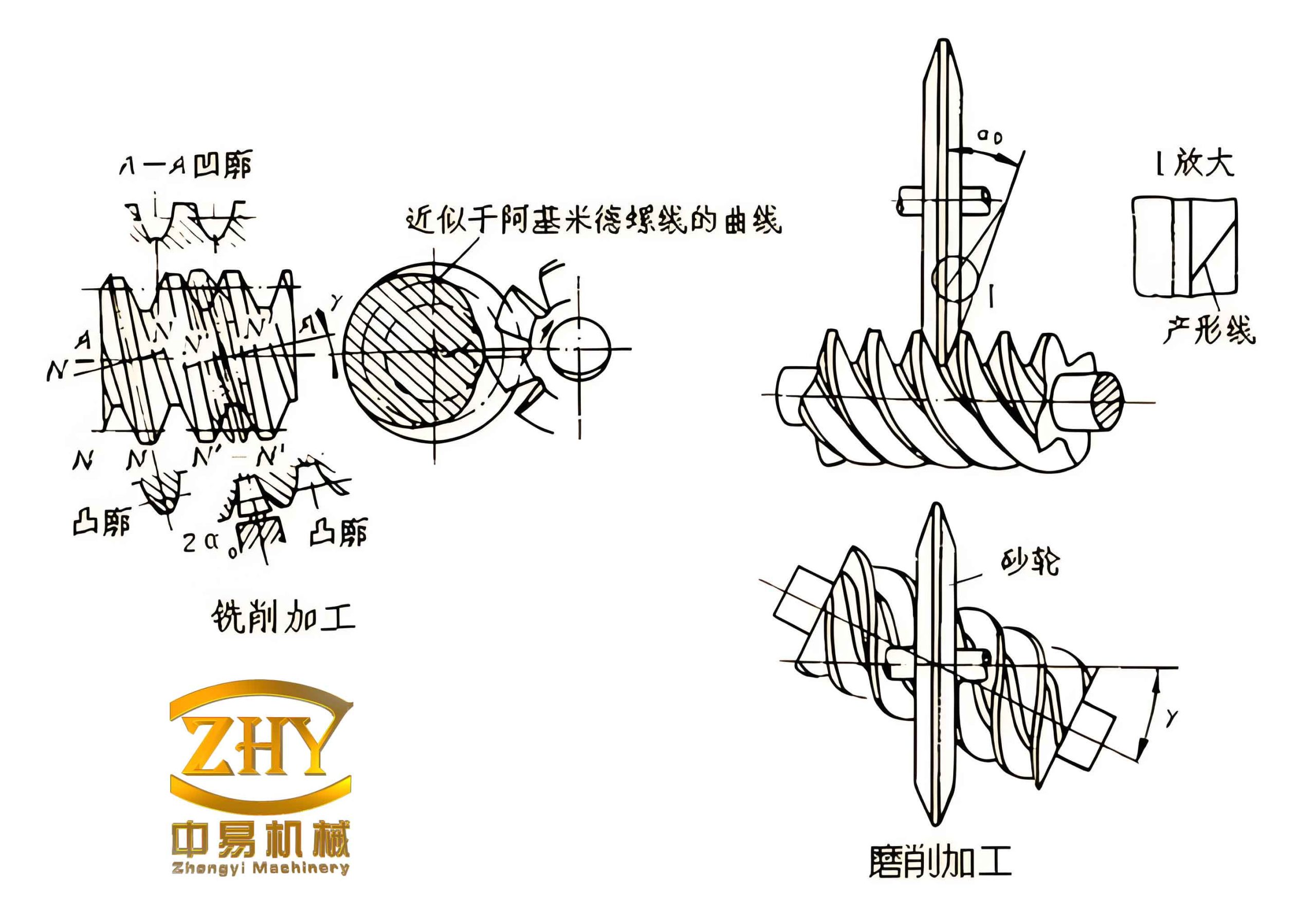
In this image, a pair of worm gears is shown, illustrating the geometry I analyze.
5. Results and Discussion
I use the parameters listed in Table 1 for the TI hourglass worm gear pair and lubricant.
| Parameter | Value |
|---|---|
| Number of teeth (worm/wheel) | 1, 40 |
| Module \(m_n\) (mm) | 5 |
| Pressure angle \(\alpha\) (°) | 20 |
| Helix angle \(\beta\) (°) | 15 (nominal) |
| Center distance \(A\) (mm) | 125 |
| Wheel face width \(b\) (mm) | 40 |
| Poisson’s ratio \(\mu_1, \mu_2\) | 0.26, 0.29 |
| Elastic modulus \(E_1, E_2\) (GPa) | 205, 209 |
| Worm speed \(n\) (r/min) | 3000 (base) |
| Backlash \(b_n\) (μm) | 6 |
| Bearing stiffness \(k\) (10^11 N/m) | 1 |
| Damping ratio \(\zeta\) | 0.1 |
| Material density \(\rho_c\) (kg/m³) | 7850 |
| Asperity friction coefficient \(\mu_a\) | 0.1 |
| Lubricant density \(\rho_r\) (kg/m³) | 864 |
| Lubricant ambient viscosity \(\eta_0\) (Pa·s) | 0.068 |
5.1 Dynamic Characteristics
Figures (described in text) show the variations of meshing force and friction force over a meshing cycle for three helix angles (\(\beta = 5^\circ, 10^\circ, 15^\circ\)) and two speeds (low and high). From the results, I observe:
- The meshing force at the entry region increases, then decreases toward the middle of the cycle, and rises again near the exit. At low speed, the entry meshing force is larger than at high speed, while the exit meshing force is smaller at low speed.
- Increasing the helix angle leads to higher meshing forces at both entry and exit, which improves transmission stability.
- The friction force first increases, then decreases, and finally increases in the opposite direction. Low speed results in larger friction at entry compared to high speed.
- As helix angle increases, the friction force becomes less sensitive to speed variation, and the maximum friction value decreases. Therefore, selecting a larger helix angle can enhance the service life of the worm gear pair.
5.2 EHL Performance
I set the dimensionless computation domain as \(X \in [-3.5, 2.0]\) with input power 5 kW and speed 3000 r/min. The boundary conditions for the Reynolds equation are \(P(X_{\mathrm{in}}, y)=0\) and \(P(X_{\mathrm{out}}, y)=0\), \(dP/dX=0\) at \(X_{\mathrm{out}}\).
I study the influence of three parameters: meshing force, mesh stiffness, and asperity friction coefficient, on oil film pressure and thickness distributions. The key findings are summarized in Table 2.
| Parameter increased | Pressure peak | Pressure fluctuation | Film thickness | Necking phenomenon |
|---|---|---|---|---|
| Meshing force | Increases | Decreases | Increases | Delayed |
| Mesh stiffness | Increases significantly | Decreases significantly | Increases | — |
| Asperity friction coefficient | Increases | — | Decreases | — |
Among these, mesh stiffness has the most profound impact on both pressure and thickness. Thus, choosing materials with better stiffness characteristics for worm gears is beneficial for lubrication performance.
6. Conclusion
In this study, I investigated the tribo-dynamics EHL of TI hourglass worm gears by coupling a simplified dynamic model with line-contact elastohydrodynamic lubrication. The following conclusions are drawn:
- During a meshing cycle, the meshing force increases at entry, decreases in the middle, and increases again near exit. Low speed yields larger entry forces than high speed, while the opposite holds at exit. Larger helix angles increase meshing forces at both extremes, promoting stable transmission of worm gears.
- The friction force initially rises, then falls, and finally rises in reverse. At entry, low speed gives higher friction. The friction magnitude is less sensitive to speed for larger helix angles, and the maximum friction reduces, which can extend the worm gear life.
- An increase in meshing force or mesh stiffness reduces initial pressure fluctuations and raises the pressure peak and film thickness. Increasing the asperity friction coefficient raises the pressure peak but reduces film thickness.
- Mesh stiffness is the dominant factor affecting oil film pressure and thickness. Therefore, selecting stiffer materials for worm gear pairs can improve lubrication effectiveness.
These insights provide guidance for the design and optimization of TI hourglass worm gears operating under mixed lubrication conditions.