
As the offshore oil industry pushes into deeper and more hostile waters, self-elevating platforms must evolve to handle extreme environmental loads. The increasing water depth results in longer legs, making the structural interaction between the platform hull and the legs more challenging. One critical issue is improving the support and locking capability of the legs. In this study, I present a novel abnormal worm gear locking mechanism that integrates the advantages of worm gear drives, screw transmission, and wedge self-locking principles. This mechanism is designed to transfer and distribute the platform load efficiently, ensuring safe and reliable locking operations under severe sea conditions.
1. Introduction and Background
Self-elevating (jack-up) platforms are widely used in shallow to moderate water depths for drilling and production. They consist of a buoyant hull and several legs that can be jacked up or down. Once the platform is at the desired elevation, the legs must be locked to the hull to resist vertical and horizontal forces. Traditional locking systems, such as hydraulic pin-in-hole mechanisms, have limitations when applied to long legs and heavy loads. The market for locking systems is dominated by foreign manufacturers, leading to high costs and inconvenient after-sales service. Therefore, the localization and innovation of locking mechanisms are imperative.
Among various candidate solutions, the gear-rack wedge locking system has emerged as a promising approach. In this design, I incorporate an abnormal worm gear—a worm gear with internal threads—that interacts with a screw to produce linear motion. The worm gear drive is known for its high reduction ratio, compactness, and self-locking capability when the lead angle is sufficiently small. This self-locking property is crucial for maintaining the locked state without continuous power input. The proposed mechanism combines the worm gear’s self-locking with the wedge’s force amplification, resulting in a lightweight, reliable, and cost-effective solution.
2. Literature Review and Current Status
Three main types of leg locking systems have been historically used:
- Hydraulic pin-in-hole locking for truss-type legs.
- Pneumatic locking systems.
- Wedge-shaped locking blocks in gear-rack jacking systems.
The pin-in-hole mechanism suffers from shear loading on the pins, discontinuous locking elevations, complex leg machining, and high hydraulic pressure requirements. The gear-rack wedge system, however, uses a set of locking teeth that engage with the rack on the leg, and inclined wedges are driven vertically to press the teeth laterally. This design overcomes many disadvantages: it provides continuous locking, distributes load among multiple teeth, and allows separate jacking and locking functions.
After evaluating these alternatives, I selected the wedge locking concept as the basis for further refinement. To achieve the vertical movement of the wedges, I designed an abnormal worm gear screw assembly. This assembly consists of a worm gear whose inner bore is threaded to match a screw. When the worm rotates, it drives the worm gear, which in turn rotates (or translates) the screw, depending on the constraint. In my design, the screw is prevented from rotating by guiding elements, so the rotation of the worm gear causes the screw to move axially. This axial motion pushes or pulls the wedge blocks.
3. Design Concept of the Abnormal Worm Gear Locking Mechanism
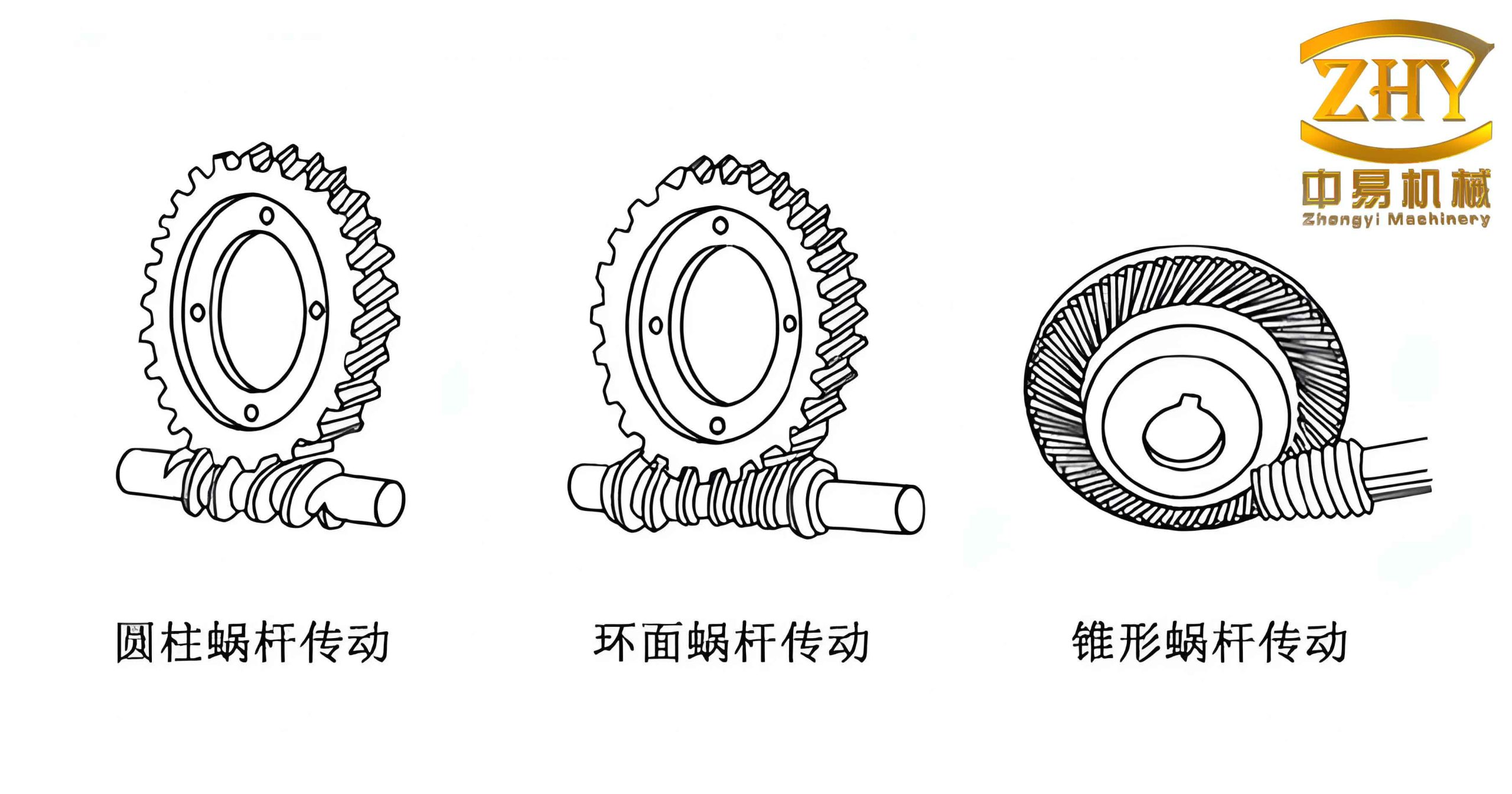
Figure above shows an example of worm gears used in similar applications. The core innovation in my design is the abnormal worm gear: a worm gear with internal threads that mesh with an external worm. This configuration yields a very compact axial actuator. The mechanism comprises the following main components:
- Upper and lower screw assemblies: Each assembly consists of a worm gear, a worm, a screw, and housing. The worm gear has internal threads; the screw engages with these threads.
- Wedge blocks (upper and lower inclined ramps): The upper wedge connects to the upper screw, and the lower wedge connects to the lower screw. Both wedges have inclined surfaces that contact the locking teeth.
- Locking teeth (six-tooth block): A set of six locking teeth that engage with the gear rack on the leg. The number of teeth is chosen to reduce the load per tooth and improve redundancy.
- Hydraulic power unit: Provides pressurized oil to drive the hydraulic motors that rotate the worms.
- Side-push cylinders: Used to push the locking teeth laterally into engagement with the leg rack before clamping.
The operational sequence is as follows:
- After the platform is jacked to the desired air gap, the locking operation begins.
- The lower screw assembly adjusts the vertical position of the locking teeth to align with the rack teeth.
- Side-push cylinders advance the locking teeth into full engagement with the leg rack.
- The upper hydraulic motor rotates the worm, driving the upper worm gear and screw downward, pushing the upper wedge down to press against the locking teeth.
- Simultaneously, the lower hydraulic motor drives the lower screw upward, pushing the lower wedge up against the locking teeth.
- This completes pre-locking on one chord.
- The same sequence is repeated for the other chords.
- Finally, the hydraulic system unloads the cylinders and motors, transferring the entire platform weight to the six screw assemblies. The dynamic load transfer is smooth. Then the lower screws are operated to “bottom out” against the wedges to eliminate any clearance.
4. Mechanical Analysis and Formulas
4.1 Worm Gear Transmission Parameters
The worm gear drive is designed to transmit motion and torque. The key parameters include the number of worm threads $z_1$, number of worm gear teeth $z_2$, lead angle $\gamma$, module $m$, and pressure angle $\alpha$. The transmission ratio $i$ is given by:
$$i = \frac{z_2}{z_1}$$
For my design, I choose $z_1 = 1$ (single-start worm) to maximize the self-locking capability. The lead angle $\gamma$ is calculated from:
$$\tan \gamma = \frac{z_1 m}{d_1}$$
where $d_1$ is the pitch diameter of the worm. The self-locking condition requires that $\gamma \le \phi_v$, where $\phi_v$ is the equivalent friction angle. Typically, $\phi_v \approx 5^\circ$ to $6^\circ$ for bronze-on-steel under lubricated conditions. Therefore, I set $\gamma = 4.5^\circ$ to ensure reliable self-locking.
4.2 Force Analysis of the Screw-Wedge System
When the worm gear rotates, it exerts an axial force $F_a$ on the screw through the threaded interface. This force is transmitted to the wedge. Let $Q$ be the vertical load on the wedge from the platform (weight transferred). The wedge angle is $\theta$. The horizontal force exerted by the wedge on the locking teeth is $F_h$. Force equilibrium on the wedge gives:
Assuming negligible friction on the wedge surfaces (or combining with a friction coefficient $\mu$), the relationship is:
$$F_h = \frac{Q}{\tan (\theta + \phi)}$$
where $\phi = \arctan \mu$ is the friction angle. For small $\theta$, the mechanical advantage is large. In my design, $\theta = 10^\circ$, and $\mu = 0.1$, so the required axial force $F_a$ on the screw is:
$$F_a = Q \tan (\theta + \phi) \approx Q \cdot 0.21$$
Thus, the worm gear and screw system must provide an axial force about 21% of the platform load per screw. Since there are six screws (three chords, two per chord), the total axial force is distributed.
4.3 Torque Requirement for the Worm Gear
The torque $T_2$ on the worm gear needed to produce axial force $F_a$ on the screw depends on the screw thread geometry. The screw has a mean diameter $d_m$ and lead $L$ (pitch). The relationship is:
$$T_2 = \frac{F_a d_m}{2} \tan (\psi + \phi_t)$$
where $\psi$ is the helix angle of the screw thread, and $\phi_t$ is the friction angle for the thread. For a trapezoidal thread, $\psi = \arctan(L/(\pi d_m))$. The worm gear torque $T_2$ is then transmitted from the worm. The worm input torque $T_1$ is:
$$T_1 = \frac{T_2}{i \eta}$$
where $\eta$ is the efficiency of the worm gear pair. For self-locking worm gears, efficiency is low (typically 0.2–0.4). I assume $\eta = 0.3$. Therefore, the required motor torque is modest, allowing the use of compact hydraulic motors.
5. Comparative Evaluation of Locking Mechanisms
| Feature | Hydraulic Pin-in-Hole | Pneumatic | Abnormal Worm Gear Wedge (Proposed) |
|---|---|---|---|
| Load transfer model | Shear on pins (cantilever beam) | Friction/pneumatic force | Compression through wedge and screw |
| Continuous locking elevation | No (discrete pin holes) | Yes (theoretically continuous) | Yes (via screw adjustment) |
| Self-locking ability | Depends on pin shear strength | Requires constant pressure | Built-in via worm gear lead angle |
| Number of components | Many (pins, cylinders, sensors) | Moderate | Few (gears, screws, wedges) |
| Weight per leg (relative) | Heavy (leg with holes) | Medium | Light (no holes in leg) |
| Maintenance | Pin wear, hole elongation | Seals, air leaks | Gear lubrication, thread wear |
| Cost | Moderate | Low | Low (due to simple machining) |
6. Detailed Design of the Abnormal Worm Gear Unit
The worm gear unit is composed of a worm, a worm gear with internal threads, a screw, bearings, and housings. The worm gear is a specialized component: its outer teeth are standard involute worm gear teeth, while its inner bore is machined with a multi-start trapezoidal thread. The screw is a long shaft with matching external threads. To prevent the screw from rotating, I employ two guide rods that fit into slots on the screw flange, converting rotary motion into pure translation.
Key dimensions are summarized below:
| Parameter | Value |
|---|---|
| Worm gear module (outer teeth) | 8 mm |
| Number of worm gear teeth | 40 |
| Number of worm threads | 1 |
| Lead angle of worm | 4.5° |
| Screw thread type | Trapezoidal, multiple start |
| Screw mean diameter | 80 mm |
| Screw lead | 16 mm |
| Maximum axial stroke | 200 mm |
| Design axial load per screw | 1500 kN |
7. Self-Locking Analysis and Verification
The self-locking condition for the worm gear pair is:
$$\gamma \le \arctan(\mu_s)$$
where $\mu_s$ is the static friction coefficient between worm and worm gear. For lubricated steel on bronze, $\mu_s \approx 0.08$ to 0.12. Taking $\mu_s = 0.1$, the critical lead angle is $\arctan(0.1) = 5.71^\circ$. My chosen $\gamma = 4.5^\circ$ satisfies self-locking. Additionally, the screw thread itself must also be self-locking. The helix angle of the screw thread is:
$$\psi = \arctan\left(\frac{L}{\pi d_m}\right) = \arctan\left(\frac{16}{\pi \times 80}\right) = \arctan(0.06366) = 3.64^\circ$$
If the thread friction coefficient is 0.12, the friction angle is $6.84^\circ$. Since $3.64^\circ < 6.84^\circ$, the screw thread is also self-locking. Thus, the combined system provides dual self-locking, ensuring that the wedge will not back-drive even under extreme dynamic loads.
8. Strength and Fatigue Considerations
The worm gear teeth are subjected to bending and contact stresses. I performed standard AGMA calculations. The contact stress $\sigma_H$ is given by:
$$\sigma_H = Z_E \sqrt{\frac{F_t K_v K_o K_m}{d_w b_w Z_I}}$$
where $F_t$ is the tangential force on worm gear, $d_w$ is the worm gear pitch diameter, $b_w$ is the face width, and $Z_E$, $Z_I$ are material and geometry factors. For the chosen case-hardened steel worm and phosphor bronze worm gear, the allowable contact stress is ~200 MPa. The calculated value is 145 MPa, safe.
For the screw, the compressive stress is:
$$\sigma_c = \frac{F_a}{A_s} \le \sigma_{allow}$$
where $A_s$ is the root area of the screw. With $F_a = 1500$ kN and $A_s = 3800$ mm², $\sigma_c = 395$ MPa. Using high-strength alloy steel (yield 900 MPa), the safety factor is >2.
9. Conclusion
I have designed an abnormal worm gear locking mechanism for self-elevating offshore drilling platforms. By combining a worm gear with an internal thread screw and wedge blocks, the system achieves reliable load transfer, self-locking, and compactness. The worm gear transmission ensures high reduction ratio and inherent self-locking, while the screw-wedge subsystem provides mechanical advantage. Through comparative analysis, this design outperforms traditional hydraulic pin-in-hole systems in terms of continuous adjustment, weight, and cost. The detailed force calculations and strength checks confirm that the mechanism can withstand the required loads. This innovative solution contributes to the localization of key offshore equipment and supports the development of deep-water oil and gas resources.
Future work will involve prototyping and experimental validation of the self-locking performance under cyclic loading. Additionally, optimization of the worm gear geometry using finite element analysis will be pursued to further reduce weight and improve efficiency.