
In our manufacturing facility, we frequently utilize a TPX6111B/2 horizontal boring machine with a worktable size of 1100 mm × 960 mm and a maximum spindle travel of 600 mm. This machine is well-suited for large box-type components, but when processing small worm gear boxes, repeated clamping and re-alignment become necessary, leading to low efficiency and compromised accuracy. To overcome these challenges, we designed a dedicated fixture that enables the complete machining of a worm gear box in a single setup, significantly improving both productivity and geometric precision.
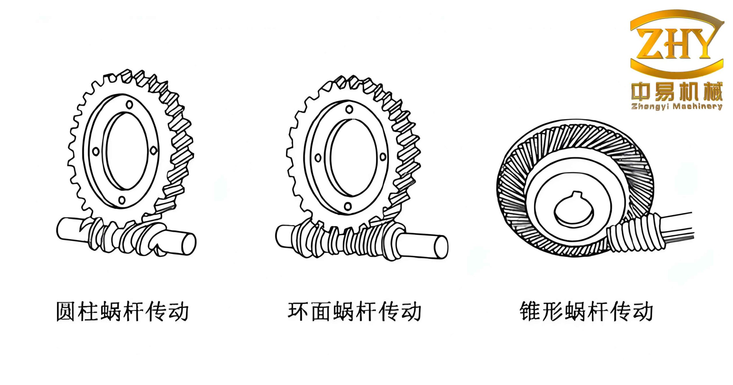
The worm gear box under consideration requires machining of four distinct groups of features. The first group comprises a ϕ40H7 ( +0.025 / 0 ) mm bore and its end face, with a coaxiality requirement of 0.05 mm and 12‑M6 threaded holes positioned with a tolerance of ϕ0.5 mm. The second group consists of a ϕ34H8 ( +0.039 / 0 ) mm bore and its end face, perpendicularity of 0.05 mm, and 4‑M8 threaded holes. The third group involves a ϕ42H8 ( +0.039 / 0 ) mm bore and its end face, coaxiality of 0.05 mm, and 4‑M8 equally spaced threaded holes. The fourth group includes a ϕ52 mm bore and a ϕ42 mm bore. The critical challenges are the strict coaxiality ( 0.05 mm ) and perpendicularity ( 0.05 mm ) tolerances, as well as the end‑face position dimensions of 191.5 +0.3/+0.2 mm, 146 0/-0.1 mm, and 38.5 ± 0.05 mm. The worm gear box has a square external shape.
Based on the structural characteristics of the worm gear box and the capabilities of our boring machine, we conceived a fixture that consists of three main components: a base plate, a rotary table, and a locating pin. The base plate is fastened to the boring machine worktable using four bolts. The rotary table is connected to the base plate through a central spindle. Four sets of holes are precisely machined on both the base and the rotary table to provide 90° indexing. After rotating the table to the desired angle, a locating pin is inserted to secure the angular position, and two additional bolts clamp the rotary table firmly to the base. The worm gear box is then mounted on the rotary table using two locating screws and clamped with pressure plates.
| Component | Function |
|---|---|
| Base Plate | Fixed to the boring machine worktable; provides a stable reference. |
| Rotary Table | Allows 90° rotation for machining all four sides of the worm gear box without re-clamping. |
| Locating Pin | Ensures accurate angular positioning at each 90° index. |
| Locating Screws | Position the worm gear box relative to the rotary table. |
| Clamping Bolts | Secure the rotary table to the base after indexing. |
The key advantage of this fixture is that it effectively transforms the large boring machine into a compact machining cell for small worm gear boxes. Without the fixture, conventional processing would require at least two separate setups: after machining the first set of features, the worm gear box would have to be unclamped, rotated, and re‑aligned for the second set. This re‑alignment process is time‑consuming and introduces cumulative positioning errors. Moreover, extending the spindle excessively to reach distant surfaces reduces rigidity and degrades surface finish and geometry. With our fixture, the worm gear box remains clamped once; all four faces are accessed simply by rotating the table. The spindle travel remains short, preserving stiffness, and the indexing repeatability of the fixture directly determines the final coaxiality and perpendicularity.
The machining procedure is as follows:
- Mount the base plate on the boring machine worktable and align it using a dial indicator.
- Place the rotary table on the base and insert the central spindle. Tighten the clamping bolts lightly.
- Install the worm gear box on the rotary table using the two locating screws. Tighten the pressure plates.
- For the first machining position (e.g., the ϕ40H7 bore), rotate the table to the appropriate angle and insert the locating pin. Fully tighten the clamping bolts.
- Machine the bore, end face, and drill/tap the 12‑M6 holes.
- Release the locating pin, rotate the table by 90° (using the index holes), re‑insert the pin, and clamp. Machine the ϕ34H8 bore and its features.
- Repeat for the remaining two sides (ϕ42H8 bore and ϕ52 mm/ϕ42 mm bores).
To ensure the fixture meets the stringent tolerance requirements, we performed a detailed error analysis. The primary sources of error are the clearance between the locating pin and the index holes, and the concentricity error of the central spindle. Let δ be the radial clearance (one‑sided) between the pin and the hole, and R the pitch radius of the index hole circle. The angular positioning error θ (in radians) introduced by this clearance is:
$$ \tan \theta \approx \theta = \frac{\delta}{R} $$
For a typical design with δ = 0.01 mm and R = 100 mm, θ = 0.0001 rad ≈ 0.006°. This angular error causes a linear displacement at the machined bore location. If the bore is located at a distance L from the rotary table center, the resulting positional deviation Δ is:
$$ \Delta = L \cdot \theta $$
For L = 150 mm, Δ = 0.015 mm, which is well within the 0.05 mm coaxiality tolerance. Additionally, the perpendicularity error between the rotary table axis and the base plane must be controlled. We specified a flatness of 0.01 mm over the 200 mm diameter for the base plate, and the rotary table run‑out was kept within 0.005 mm. These values ensure that the perpendicularity requirement of 0.05 mm for the ϕ34H8 bore can be satisfied.
In practice, we produced a batch of three worm gear boxes using this fixture. The measured results are summarized in Table 2 and Table 3.
| Sample | ϕ40H7 Coaxiality (mm) | ϕ42H8 Coaxiality (mm) | ϕ34H8 Perpendicularity (mm) |
|---|---|---|---|
| 1 | 0.05 | 0.04 | 0.04 |
| 2 | 0.03 | 0.03 | 0.04 |
| 3 | 0.04 | 0.04 | 0.03 |
| Specification | 191.5 +0.3/+0.2 | 146 0/-0.1 | 38.5 ±0.05 |
|---|---|---|---|
| Sample 1 | 191.75 | 145.95 | 38.52 |
| Sample 2 | 191.72 | 145.94 | 38.55 |
| Sample 3 | 191.78 | 145.97 | 38.49 |
All measured values are within the specified tolerances. Notably, the coaxiality and perpendicularity results are consistently below 0.05 mm, demonstrating the effectiveness of the fixture design. The dimensional deviations are also acceptable, with the worst‑case deviation being 0.05 mm on the 38.5 mm dimension (sample 2), still within the ±0.05 mm band.
Beyond geometric accuracy, the fixture dramatically improved productivity. Conventional two‑setup machining required about 45 minutes per worm gear box, including setup, alignment, and machining. With the fixture, the total cycle time per worm gear box reduced to 35 minutes, a reduction of 22%. The time savings come primarily from eliminating the second setup and the associated dial‑indicating procedures. The productivity gain can be expressed as:
$$ \text{Productivity Improvement} = \frac{T_{\text{old}} – T_{\text{new}}}{T_{\text{old}}} \times 100\% = \frac{45-35}{45} \times 100\% \approx 22.2\% $$
Furthermore, the risk of operator‑induced errors is minimized, and the process becomes more repeatable. The fixture also allows us to process other small box‑type components by simply modifying the localizing features on the rotary table. This modularity makes the investment highly cost‑effective.
In summary, the dedicated fixture for worm gear box machining on a boring machine has proven to be a robust solution. It enables single‑setup processing of all four faces, maintains strict coaxiality and perpendicularity tolerances, and improves production efficiency by over 20%. The design principles—precision indexing, rigid clamping, and error analysis—can be extended to similar worm gear box variants and other prismatic parts. By incorporating such fixtures, we have enhanced the versatility of our horizontal boring machines and achieved consistent quality in batch production.