
In my research on worm gear transmission systems, I have focused on a novel plane enveloping internal meshing worm gear, which offers advantages such as high load capacity, compact structure, and the ability to achieve multiple output loads. The generating plane inclination angle is a critical parameter that significantly influences the meshing performance of this worm gear drive. In this study, I systematically investigate the effect of this angle on the induced normal curvature and contact stress distribution, aiming to identify the optimal range for the generating plane inclination angle.
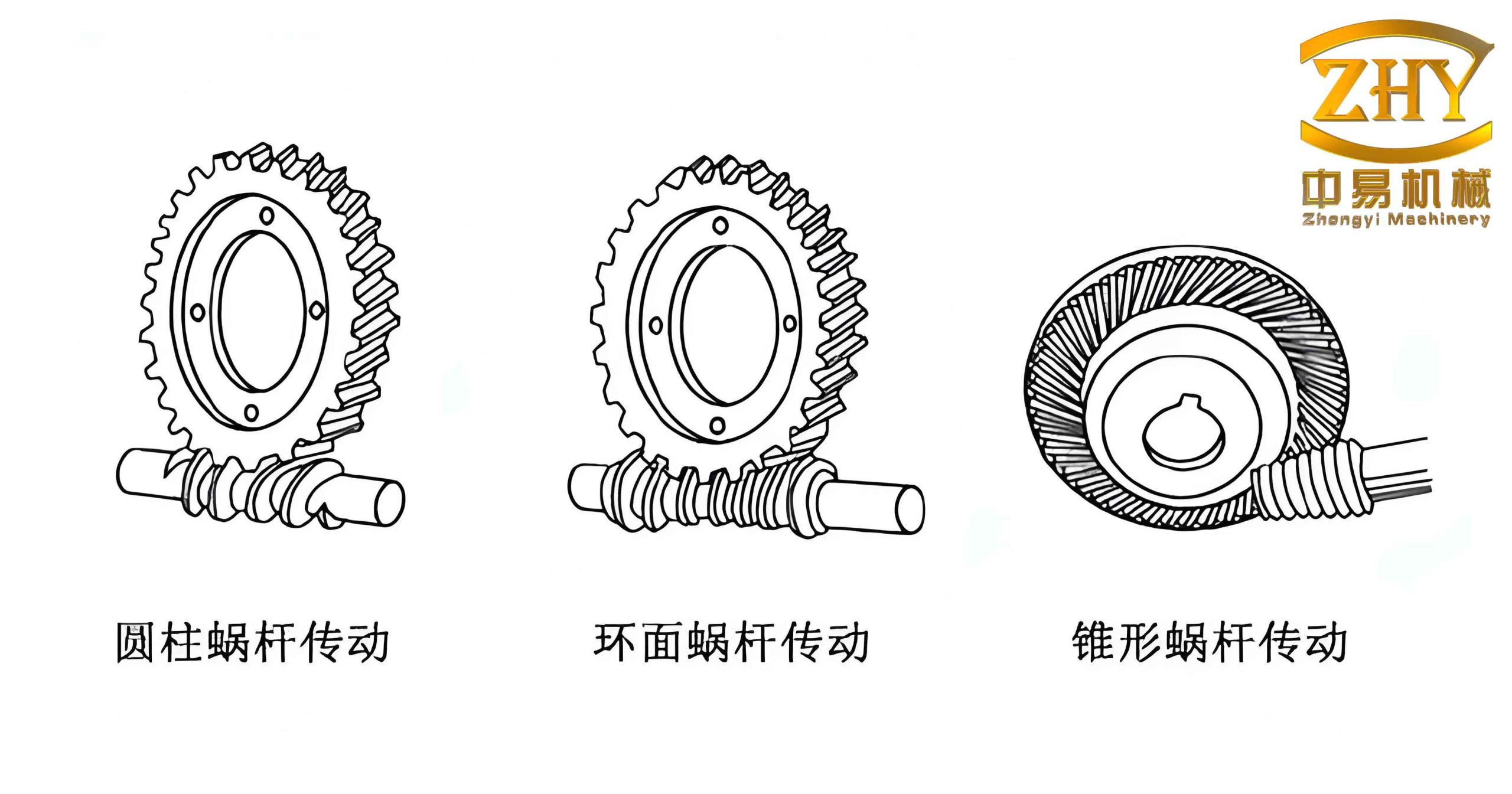
1. Transmission Principle of the Novel Internal Meshing Worm Gear
1.1 Coordinate System Establishment
I established a set of coordinate systems for the internal meshing worm gear drive, as shown in Figure 1 of the original study (not reproduced here). The fixed coordinate systems S1 and S2 are attached to the worm and worm wheel, respectively. The moving coordinate systems S1′ and S2′ rotate with angular velocities ω1′ and ω2′. The generating plane Σ is represented by the coordinate system S0, with its origin O located on the base circle. The inclination angle of the generating plane is denoted by β. The center distance between the worm and worm wheel is A, and the installation inclination angle of the worm wheel is δF.
The coordinate transformation matrix from the worm wheel moving system S2′ to the worm moving system S1′ is given by:
$$
\mathbf{M}_{2’1′} = \begin{bmatrix}
p_1 + l_2 p_2 & l_2 p_4 – p_3 & -l_1 g_2 & A g_1 \\
l_2 p_3 – p_4 & p_2 + l_2 p_1 & -l_1 g_1 & -A g_2 \\
l_1 h_2 & l_1 h_1 & l_2 & 0 \\
0 & 0 & 0 & 1
\end{bmatrix}
$$
where:
$$
g_1 = \cos\phi_1,\quad g_2 = \sin\phi_1,\quad h_1 = \cos\phi_2,\quad h_2 = \sin\phi_2,\quad l_1 = \cos\delta_F,\quad l_2 = \sin\delta_F
$$
$$
p_1 = g_1 h_1,\quad p_2 = g_2 h_2,\quad p_3 = g_1 h_2,\quad p_4 = g_2 h_1
$$
The transformation matrix from the generating plane system S0 to the worm wheel system S2′ is:
$$
\mathbf{M}_{02′} = \begin{bmatrix}
0 & 1 & 0 & 0 \\
-\cos\beta & 0 & -\sin\beta & r \\
-\sin\beta & 0 & \cos\beta & 0 \\
0 & 0 & 0 & 1
\end{bmatrix}
$$
Here, r is the base circle radius, and u, v are the coordinates of the contact point in the generating plane.
1.2 Meshing Equation
The necessary condition for correct meshing between the worm and worm gear is that the normal vector at the contact point is perpendicular to the relative velocity. This yields the meshing equation:
$$
\Phi = \mathbf{v}_{1’2′} \cdot \mathbf{i}_0 = 0
$$
After derivation, the meshing condition can be expressed as:
$$
v = \frac{B_1}{B_2}
$$
where:
$$
B_1 = u\cos\beta\sin\delta_F + A\cos\beta\cos\phi_2\sin\delta_F – u\cos\phi_2\cos\delta_F\sin\beta – i_c u\cos\beta + r\cos\delta_F\sin\beta\sin\phi_2 – A\cos\delta_F\sin\beta
$$
$$
B_2 = \cos\delta_F \sin\phi_2 \quad (\phi_2 \neq 0)
$$
Here, i_c = z_1 / z_2 is the transmission ratio, with z_1 and z_2 being the number of worm starts and worm wheel teeth, respectively.
1.3 Tooth Surface Equations
The tooth surfaces of the worm and worm gear are generated by the trajectory of contact points. The parametric equations in the moving coordinate systems are:
$$
[\mathbf{r}_{1′} \quad 1]^T = \mathbf{M}_{2’1′} \cdot \mathbf{M}_{02′} \cdot [\mathbf{r}_p \quad 1]^T
$$
$$
[\mathbf{r}_{2′} \quad 1]^T = \mathbf{M}_{02′} \cdot [\mathbf{r}_p \quad 1]^T
$$
subject to the constraints:
$$
v = B_1 / B_2,\quad u = c,\quad \phi_2 = i_c \phi_1
$$
where c is a constant. Based on these equations, I built a three-dimensional model of the internal meshing worm gear drive. The unique structure of this worm gear enables simultaneous multi-load output.
1.4 Induced Normal Curvature
To evaluate the meshing performance, I introduced the induced normal curvature k_{1’2′}, which is a key parameter influencing contact stress. The formula for the induced normal curvature is:
$$
k_{1’2′} = \frac{ \boldsymbol{\omega}_{1’2′} \times \mathbf{i}_0 – \mathbf{v}_{1’2′} \cdot \left( \frac{d\mathbf{i}_0}{ds} \right) }{ \Psi }
$$
where:
$$
\Psi = \frac{d\Phi}{dt} + (\boldsymbol{\omega}_{1’2′},\ \mathbf{i}_0,\ \mathbf{v}_{1’2′})
$$
The components of the relative angular velocity vector in the generating plane coordinate system are:
$$
x_{\omega 0} = \sin\beta (i_c – \sin\delta_F) – \cos\beta \cos\delta_F \cos\phi_2
$$
$$
y_{\omega 0} = \cos\delta_F \sin\phi_2
$$
$$
z_{\omega 0} = -\cos\beta (i_c – \sin\delta_F) – \cos\delta_F \cos\phi_2 \sin\beta
$$
2. Influence of the Generating Plane Inclination Angle on Induced Normal Curvature
2.1 Selection of Key Analysis Points
I employed the Hertz contact stress model to connect the induced normal curvature with contact stress:
$$
\sigma_H = \sqrt{ \frac{ F_n E_1 E_2 k_{1’2′} }{ l [E_1 (1-\mu_2^2) + E_2 (1-\mu_1^2)] } }
$$
From this equation, it is evident that smaller induced normal curvature leads to lower contact stress. Therefore, optimizing the generating plane inclination angle β to minimize k_{1’2′} is crucial for improving the meshing performance of the worm gear.
I set the following baseline parameters: center distance A = 80 mm, worm starts z_1 = 1, worm wheel teeth z_2 = 40, installation angle δ_F = 35°, worm wheel tip diameter d_a = 67 mm, root diameter d_f = 62 mm, base circle radius r = 23 mm. The parameter u ranges from u_min = 57.6 mm (at root) to u_max = 63 mm (at tip).
Figure 4 of the original study (not reproduced) shows that the induced normal curvature decreases linearly from the root to the tip of the worm wheel tooth. The maximum curvature occurs at the root, indicating the worst contact condition. Hence, I selected u = 57.6 mm for subsequent analysis.
2.2 Effect of Worm Wheel Tooth Number
I investigated how the number of worm wheel teeth z_2 affects the relationship between β and k_{1’2′}. The parameters were: A = 80 mm, δ_F = 35°, r = 23 mm, u = 57.6 mm, and z_1 = 1. The results are summarized in the table below for different rotation angles φ_2.
| β (°) | z_2 = 20 | z_2 = 30 | z_2 = 40 | z_2 = 50 |
|---|---|---|---|---|
| 0 | 0.0245 | 0.0221 | 0.0203 | 0.0189 |
| 18 | 0.0112 | 0.0098 | 0.0087 | 0.0079 |
| 24 | 0.0105 | 0.0091 | 0.0081 | 0.0073 |
| 30 | 0.0108 | 0.0093 | 0.0083 | 0.0075 |
| 36 | 0.0115 | 0.0099 | 0.0088 | 0.0080 |
| 90 | 0.0350 | 0.0312 | 0.0285 | 0.0264 |
From the analysis, I observed that for small rotation angles (φ_2 < 20°), the optimal β range was approximately 0°–36°. However, as φ_2 increased, the best range narrowed to 18°–36°. Figure 7 in the original study (not shown) further confirms that within 18°–36°, the induced normal curvature reaches minimum values for all tested tooth numbers.
2.3 Effect of Center Distance
I then varied the center distance A while keeping other parameters constant: z_2 = 40, δ_F = 35°, r = 23 mm, u = 57.6 mm. The results for different β and A are presented below.
| β (°) | A = 60 mm | A = 80 mm | A = 100 mm | A = 120 mm |
|---|---|---|---|---|
| 0 | 0.0198 | 0.0203 | 0.0207 | 0.0211 |
| 18 | 0.0085 | 0.0087 | 0.0089 | 0.0091 |
| 24 | 0.0079 | 0.0081 | 0.0083 | 0.0085 |
| 30 | 0.0081 | 0.0083 | 0.0085 | 0.0087 |
| 36 | 0.0086 | 0.0088 | 0.0090 | 0.0092 |
| 90 | 0.0279 | 0.0285 | 0.0290 | 0.0294 |
Again, I found that the optimal β range consistently fell within 18°–36° regardless of the center distance. The induced normal curvature remains relatively stable in this range, providing a robust design recommendation.
3. Conclusion
Through my systematic analysis of the plane enveloping internal meshing worm gear drive, I draw the following conclusions:
1. The induced normal curvature along the contact line decreases linearly from the worm wheel root to the tip. The root experiences the highest curvature, indicating the worst meshing condition, which is consistent with finite element analysis results showing maximum contact stress at the root.
2. Regardless of variations in worm wheel tooth number or center distance, the optimal generating plane inclination angle β lies in the range of 18° to 36°. Within this range, the induced normal curvature reaches its minimum, leading to reduced contact stress and improved meshing performance of the worm gear.
3. The findings provide a practical guideline for the initial design of internal meshing worm gear drives, reducing the need for extensive iterative optimization. Future work should consider multi-parameter coupling effects to further refine the design methodology.