
In the study of straight spur gears, the phenomenon of “tip interference” and sudden load changes at the transition between single and double tooth contact regions is a significant source of vibration and noise. Tooth profile modification is widely adopted to alleviate these issues, reducing load fluctuations, transmission errors, and flash temperature. In this work, we systematically investigate the influence of modification parameters on load sharing, transmission error, and flash temperature for straight spur gears. Using the time-varying mesh stiffness and Blok’s flash temperature theory, we first determine the optimal modification parameters under single-objective conditions. Then, based on fuzzy comprehensive decision theory, we derive the optimum parameters under multi-objective considerations. A correction factor \( X_c \) is introduced to quantify the maximum modification amount for multi-objective design. We present a comprehensive set of formulas and tables to summarize the findings. All analyses are performed on a typical straight spur gear pair whose basic parameters are listed in Table 1.
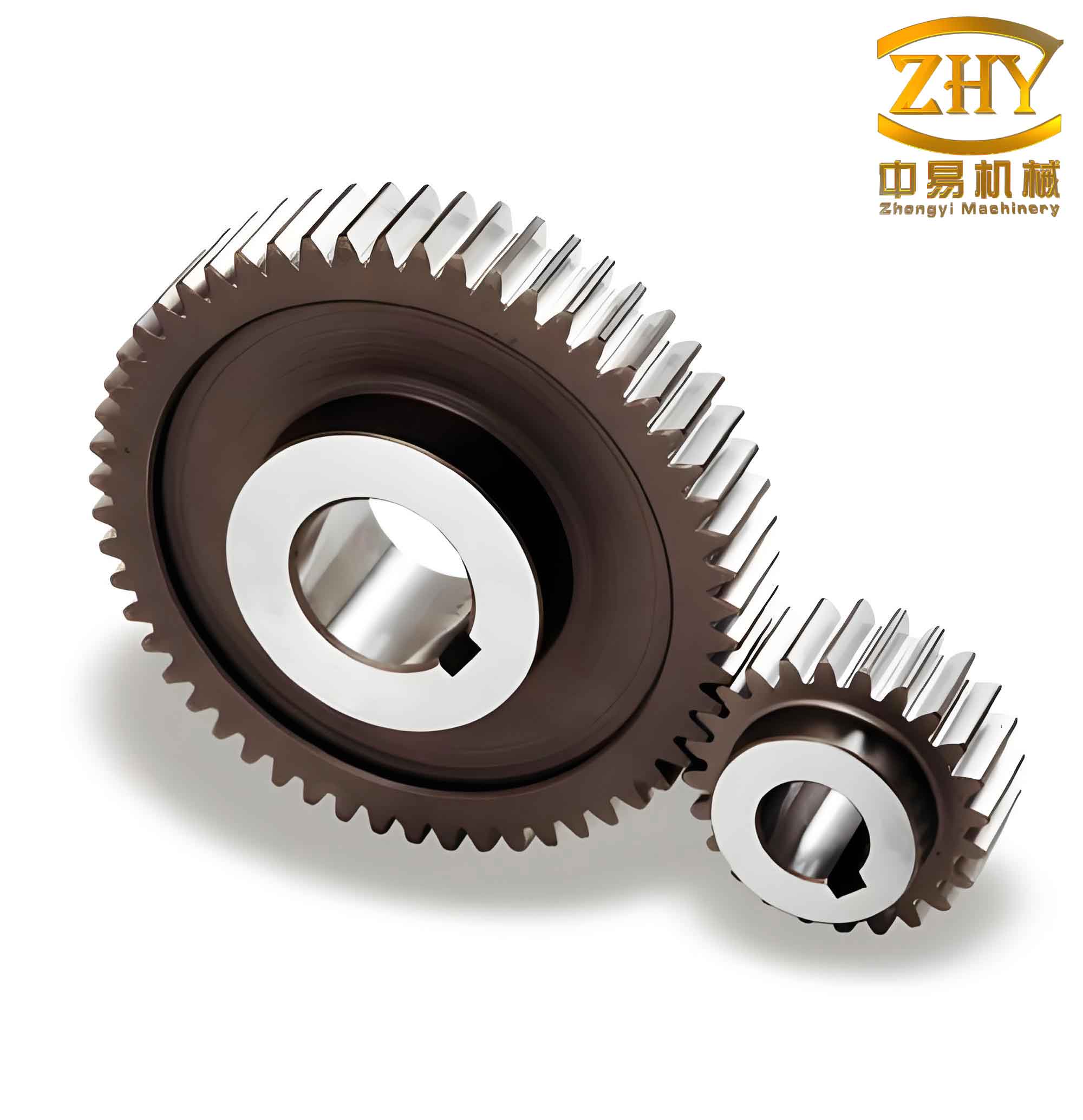
Table 1: Basic parameters of the studied straight spur gear pair
| Parameter | Value |
|---|---|
| Number of teeth (pinion/gear) | 27 / 35 |
| Module \( m \) (mm) | 3 |
| Pressure angle \( \alpha \) (°) | 20 |
| Face width \( b \) (mm) | 25 |
| Profile shift coefficients \( x_1/x_2 \) | 0 / 0 |
| Power \( P \) (kW) | 80 |
| Pinion speed \( n_1 \) (r/min) | 2000 |
| Young’s modulus \( E \) (MPa) | 2.06×10^5 |
| Poisson’s ratio \( \nu \) | 0.3 |
| Density \( \rho \) (kg/m³) | 7850 |
| Specific heat capacity \( c \) (J/(kg·K)) | 465 |
| Thermal conductivity \( \lambda \) (W/(m·K)) | 46 |
1. Mechanism of Tooth Profile Modification for Straight Spur Gears
We adopt simultaneous modification on both the pinion and gear tooth tips. The modified amount along the line of action follows a power function:
$$ \Delta = \Delta_{\max} \left( \frac{x}{L} \right)^{\beta_c} $$
where \( \Delta_{\max} \) is the maximum modification amount, given by \( \Delta_{\max} = \delta \pm \Delta_{fb} \) with \( \delta \) being the deformation at the single-tooth/double-tooth transition points B and D, and \( \Delta_{fb} \) the base pitch error. The variable \( x \) is the distance from point K in the double-tooth meshing region to the single-tooth boundary point B or D, and \( L \) is the length of the double-tooth contact segment. The exponent \( \beta_c \) is the modification index.
2. Influence of Modification on Load Sharing and Transmission Error for Straight Spur Gears
For a straight spur gear pair with contact ratio between 1 and 2, the load distribution in the double-tooth region can be modeled as two parallel springs. The load sharing ratio for tooth pair \( i \) is:
$$ \zeta_1 = \frac{k_1}{k_1 + k_2} \left[ 1 + \frac{k_2(\Delta_2 – \Delta_1)}{w} \right] $$
$$ \zeta_2 = \frac{k_2}{k_1 + k_2} \left[ 1 + \frac{k_1(\Delta_1 – \Delta_2)}{w} \right] $$
where \( k_1, k_2 \) are the mesh stiffnesses of the two tooth pairs (computed via the method in reference), \( w \) is the normal load per unit width. The transmission error (TE) is:
$$ TE = \begin{cases}
\frac{w + k_1\Delta_1 + k_2\Delta_2}{k_1 + k_2}, & |\Delta_1 – \Delta_2| \le \min(w/k_1, w/k_2) \\
\Delta_1 + w/k_1, & \Delta_2 – \Delta_1 > w/k_1 \\
\Delta_2 + w/k_2, & \Delta_1 – \Delta_2 > w/k_2
\end{cases} $$
For the unmodified straight spur gear, the load sharing ratio jumps from 0.64 to 1 at points B and D (a 36% sudden change), and the transmission error fluctuates between 16.2 μm and 26.6 μm, a variation of 39.1%. The optimal maximum modification amount for single-objective (load or TE) equals the deformation at points B and D, which is 26.5 μm for our case.
Table 2: Effect of modification parameters on load sharing and TE (single-objective optimum: \( \Delta_{\max}=26.5 \) μm, \( \beta_c=1.43 \), long modification)
| Modification parameter | Load jump reduction | TE fluctuation reduction |
|---|---|---|
| \( \Delta_{\max} \) too small | Incomplete smoothing | Residual sudden changes |
| \( \Delta_{\max} \) too large | Reduced double-tooth region width | Increased TE variation |
| \( \beta_c \) too low | Nonlinear distortion | Peak error shift |
| \( \beta_c = 1.43 \) | Nearly linear transition | Minimum peak-to-peak error |
| Short modification | Higher load spike | Larger error fluctuation |
3. Influence of Modification on Flash Temperature for Straight Spur Gears
The Blok flash temperature formula for straight spur gears is:
$$ \theta_{fla} = 0.785 \times \frac{f w_b \left| v_{\rho1} – v_{\rho2} \right|}{\left( \lambda_1 \gamma_1 c_1 \sqrt{v_{\rho1}} + \lambda_2 \gamma_2 c_2 \sqrt{v_{\rho2}} \right) \sqrt{b_1}} $$
where \( w_b \) is the normal load per unit width, \( v_{\rho1}, v_{\rho2} \) are tangential velocities at the contact point, \( f \) is the friction coefficient, \( \lambda, \gamma, c \) are thermal conductivity, specific weight, and specific heat of the gear material, and \( b_1 \) is the half-contact width. The modification reduces the load at the entry and exit points, thereby lowering the flash temperature. For our straight spur gear, the unmodified maximum flash temperature is 48°C at point A. After optimal modification for flash temperature alone, the maximum drops to 33.7°C, a reduction of 27%.
The optimal parameters for minimizing flash temperature differ from those for load/TE. The maximum flash temperature under modification always occurs in the double-tooth region near the entry side. The midpoint of the double-tooth region (point B’) experiences a fixed flash temperature independent of modification, because at that point the two meshing teeth have equal modification amounts. Setting the maximum flash temperature at B’ gives the optimal \( \Delta_{\max} \) equal to the deformation at B’, which is 16.2 μm for our straight spur gear. The optimal index remains \( \beta_c = 1.43 \).
4. Fuzzy Comprehensive Decision for Multi-Objective Optimization of Straight Spur Gear Modification
To simultaneously optimize load distribution, transmission error, and flash temperature, we employ fuzzy comprehensive decision theory. We define the alternative set for maximum modification amount:
$$ \tilde{B} = \{ 26.5,\ 24.5,\ 22.5,\ 20.5,\ 18.5,\ 16.2 \} \ \text{(unit: μm)} $$
The factor set is:
$$ \tilde{A} = \{ \text{Load sharing},\ \text{Transmission error},\ \text{Flash temperature} \} $$
The weight vector is determined by the sensitivity of each factor to a 5 μm perturbation in \( \Delta_{\max} \). Based on our analysis (Table 3), we obtain:
$$ \tilde{a} = (0.5,\ 0.4,\ 0.1) $$
Table 3: Sensitivity of factors to a 5 μm change in \( \Delta_{\max} \) (from 21.5 μm to 26.5 μm for load/TE; from 16.2 μm to 21.2 μm for flash temperature)
| Factor | Change percentage | Normalized weight |
|---|---|---|
| Average load jump | 6.9% → 0% (actual jump decrease 6.9%) | 0.5 |
| TE fluctuation | 5.64% decrease in fluctuation rate | 0.4 |
| Max flash temperature | 1.48% increase | 0.1 |
The fuzzy relation matrix \( \tilde{R} \) is constructed based on expert knowledge and engineering judgment:
$$ \tilde{R} = \begin{bmatrix}
0.6 & 0.5 & 0.4 & 0.3 & 0.2 & 0.1 \\
0.5 & 0.45 & 0.4 & 0.35 & 0.3 & 0.2 \\
0.2 & 0.25 & 0.3 & 0.35 & 0.4 & 0.5
\end{bmatrix} $$
Applying the Zadeh operator (max-min composition) yields the fuzzy decision vector:
$$ \tilde{C} = \tilde{a} \circ \tilde{R} = (0.5,\ 0.5,\ 0.4,\ 0.35,\ 0.3,\ 0.2) $$
To resolve ties, we use the weighted average method:
$$ B^* = \frac{\sum_{j=1}^{m} C_j B_j}{\sum_{j=1}^{m} C_j} $$
For our straight spur gear:
$$ B^* = \frac{0.5 \times 26.5 + 0.5 \times 24.5 + 0.4 \times 22.5 + 0.35 \times 20.5 + 0.3 \times 18.5 + 0.2 \times 16.2}{0.5+0.5+0.4+0.35+0.3+0.2} \approx 22.4\ \mu\text{m} $$
Thus, the multi-objective optimal maximum modification is taken as 22.5 μm.
5. Generalization via Correction Factor \( X_c \) for Straight Spur Gears
We further analyze several straight spur gear pairs with different geometry and load conditions (shown in Table 4). The multi-objective optimal modification consistently equals about 84.5% of the single-objective optimum (deformation at B or D). Therefore, we introduce a correction factor \( X_c = 0.845 \). The recommended formula for multi-objective tooth profile modification of straight spur gears is:
$$ \Delta = X_c \cdot \Delta_{\max} \left( \frac{x}{L} \right)^{\beta_c} $$
with \( \Delta_{\max} \) taken as the deformation at points B and D (single-objective optimum), and \( \beta_c = 1.43 \). The modification form should be long modification (full double-tooth region).
Table 4: Statistical analysis of optimal modification amounts for different straight spur gear pairs
| Teeth (z₁/z₂) | Module (mm) | Power (kW) / speed (r/min) | Single-objective \( \Delta_{\max} \) (μm) | Multi-objective \( \Delta_{\max} \) (μm) | \( X_c \) |
|---|---|---|---|---|---|
| 17/25 | 3 | 20/2000 | 38.0 | 32.0 | 0.842 |
| 23/30 | 2 | 50/1500 | 51.5 | 43.5 | 0.845 |
| 27/35 | 3 | 80/2000 | 26.5 | 22.5 | 0.849 |
| 33/45 | 4 | 150/2500 | 18.9 | 15.9 | 0.841 |
| 43/92 | 2.5 | 200/3000 | 17.1 | 14.5 | 0.848 |
| Average | 0.845 | ||||
6. Validation on the Studied Straight Spur Gear
Applying the multi-objective optimal parameters (\( \Delta_{\max}=22.5 \) μm, \( \beta_c=1.43 \), long modification) to our straight spur gear, we obtain:
- Load jump: from 0.946 to 1.0 (jump magnitude 0.054, i.e., 5.4% sudden change, compared to 36% without modification)
- Transmission error fluctuation: from 26.6 μm to 25.1 μm (peak-to-peak 1.5 μm, fluctuation rate 5.7%)
- Maximum flash temperature: 34.4°C (28.3% lower than unmodified 48°C)
These results demonstrate a balanced improvement across all three critical performance indices for the straight spur gear.
Conclusion
- For straight spur gears, the maximum modification amount \( \Delta_{\max} \) determines the continuity of load sharing, while the modification index \( \beta_c \) and modification form influence the nonlinearity of load distribution and transmission error fluctuation. When \( \Delta_{\max} \) exceeds the optimal value, the single-tooth region expands and the double-tooth region shrinks.
- Under single-objective optimization for load distribution or transmission error, the optimal parameters for straight spur gears are: \( \Delta_{\max} \) equal to the deformation at points B and D, \( \beta_c = 1.43 \), and long modification.
- Under single-objective optimization for flash temperature, the optimal \( \Delta_{\max} \) equals the deformation at the midpoint B’ of the entry-side double-tooth region (which is about 61% of the deformation at B/D for the studied gear), with the same index and long modification.
- The multi-objective optimal maximum modification amount for straight spur gears is given by \( \Delta = X_c \Delta_{\max} (x/L)^{\beta_c} \), where \( X_c = 0.845 \), \( \beta_c = 1.43 \), and the modification form is long modification. This formula provides a practical guideline for designing modified straight spur gears with reduced load shock, low transmission error fluctuation, and improved scuffing resistance.