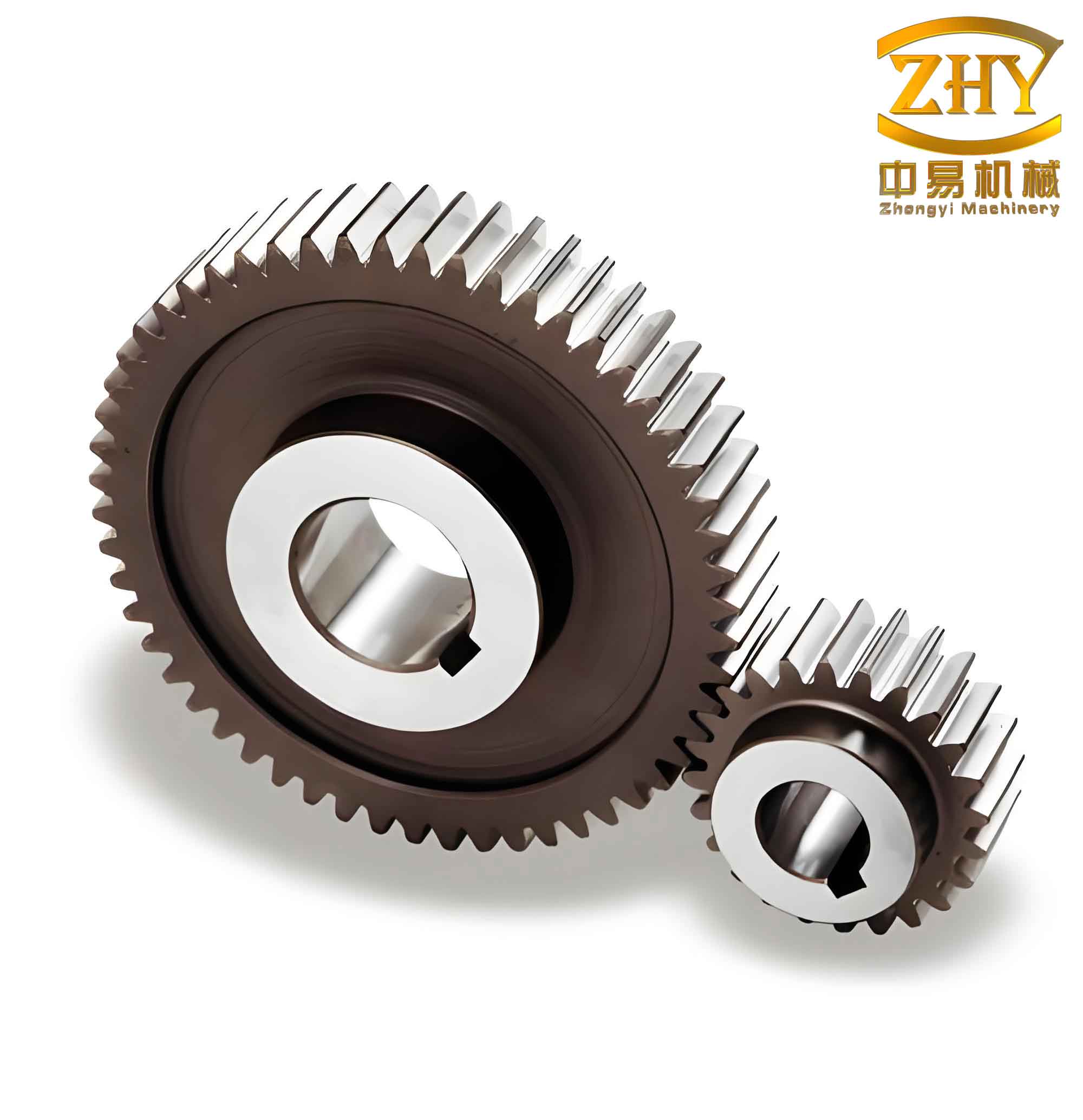
In my research, I have dedicated significant effort to understanding the cold extrusion forming process of a straight spur gear. The straight spur gear is a fundamental component in mechanical transmission systems, and its forming quality directly affects the performance and service life of the entire assembly. Through extensive finite element numerical simulations, I have systematically investigated the influence of die geometry, billet dimensions, and process parameters on the deformation behavior and defect formation during the cold extrusion of a straight spur gear. The objective is to provide a theoretical basis and practical guidance for die design and process optimization, ensuring high-quality gear forming with minimal defects such as underfilling, cracking, and die wear.
My study focuses on the cold extrusion of a straight spur gear with a fixed pitch circle diameter, while varying the tooth number and module. The billet diameter is initially set equal to the addendum circle diameter of the gear. The die structure incorporates a mandrel to form the central hole and a cavity with gear-shaped die teeth to form the outer profile. The material is assumed to be elasto-plastic with isotropic hardening, and the friction condition follows the Coulomb model with a constant coefficient. The governing equations for the deformation process are based on the principle of volume constancy and the equilibrium equations in cylindrical coordinates.
The deformation degree during extrusion is characterized by the extrusion ratio, defined as the ratio of the billet cross-sectional area to the product cross-sectional area. For a straight spur gear, the cross-sectional area of the extruded part includes the gear tooth area and the root area. I derived the following formula for the extrusion ratio:
$$
R = \frac{A_0}{A_f} = \frac{\pi r_b^2}{\pi r_f^2 + N \cdot A_{tooth}}
$$
where \( r_b \) is the billet radius, \( r_f \) is the root radius of the straight spur gear, \( N \) is the number of teeth, and \( A_{tooth} \) is the cross-sectional area of one tooth space. The tooth space area can be approximated using the gear module \( m \) and the addendum coefficient:
$$
A_{tooth} \approx \frac{1}{2} m^2 \left( \frac{\pi}{2} – 2 \tan \alpha_0 \right) + \text{fillet area}
$$
In my simulations, I considered three cases of straight spur gear with different tooth numbers and modules, while keeping the pitch circle diameter constant at a reference value. The key parameters are summarized in Table 1.
| Case | Tooth Number \( N \) | Module \( m \) (mm) | Addendum Circle Diameter \( d_a \) (mm) | Billet Diameter \( d_b \) (mm) | Extrusion Ratio \( R \) |
|---|---|---|---|---|---|
| A | 12 | 3 | 42 | 42 | 1.35 |
| B | 18 | 2 | 40 | 40 | 1.52 |
| C | 24 | 1.5 | 40.5 | 40.5 | 1.68 |
The die structure for each case is designed with an entry angle of 60 degrees, a bearing length of 2 mm, and a die tooth profile corresponding to the straight spur gear geometry. The die teeth act as flow dividers during extrusion. In case A (low tooth number, large module), the deformation degree is relatively small. The velocity field inside the die reveals that the metal flows preferentially toward the gear root region, while the tooth tip receives insufficient material. This results in a severe underfilling at the tooth crest and even surface cracking due to tensile stresses. The radial stress and axial stress distributions indicate that the tooth tip experiences high tensile stress exceeding the material’s ultimate strength.
To quantify the stress state, I computed the effective stress using the von Mises criterion:
$$
\bar{\sigma} = \sqrt{\frac{1}{2} \left[ (\sigma_r – \sigma_\theta)^2 + (\sigma_\theta – \sigma_z)^2 + (\sigma_z – \sigma_r)^2 + 6(\tau_{r\theta}^2 + \tau_{\theta z}^2 + \tau_{zr}^2) \right] }
$$
The strain distribution is described by the effective strain, which is integrated from the incremental plastic strain:
$$
\bar{\varepsilon} = \int \sqrt{\frac{2}{3} d\varepsilon_{ij} d\varepsilon_{ij}}
$$
Table 2 lists the maximum effective stress and effective strain values observed in the tooth tip region for each case.
| Case | Maximum Effective Stress (MPa) | Maximum Effective Strain |
|---|---|---|
| A | 620 | 0.45 |
| B | 550 | 0.62 |
| C | 480 | 0.78 |
Case B (medium tooth number) shows improvement in tooth filling, but still exhibits underfilling at the tooth tip and an inward concavity at the extruded head. The concavity arises because the central metal flows slower than the peripheral metal due to frictional constraints. The velocity difference can be expressed by the ratio of central velocity to peripheral velocity:
$$
\frac{v_c}{v_p} = 1 – \frac{2 \mu \cdot L}{r_0} \cdot \frac{\sigma_0}{\bar{\sigma}}
$$
where \( \mu \) is the friction coefficient, \( L \) is the die bearing length, \( r_0 \) is the billet radius, and \( \sigma_0 \) is the yield strength. In case B, this ratio decreases, leading to a concave head profile.
Case C (high tooth number, small module) yields the best filling quality. The tooth tips are completely filled, but the head of the extruded straight spur gear exhibits a pronounced convex belly (bulging) at the tooth region and a concave center. The bulging is caused by the high circumferential compressive stress that forces the tooth metal to expand outward. The degree of bulging can be quantified by the ratio of the maximum radial displacement at the tooth to the nominal radius:
$$
\delta = \frac{u_r}{r_{nom}} = \frac{1}{E} \left[ \sigma_r – \nu (\sigma_\theta + \sigma_z) \right]
$$
Table 3 summarizes the defect types and their severity for each case.
| Case | Tooth underfill | Tooth surface crack | Head concavity | Tooth bulging |
|---|---|---|---|---|
| A | Severe | Present | None | None |
| B | Moderate | None | Mild | None |
| C | None | None | Moderate | Present |
Based on these observations, I performed a parametric study to optimize the die design for straight spur gear cold extrusion. The key design parameter is the die entry angle. A smaller entry angle reduces the radial component of the forging force, facilitating metal flow toward the tooth tips. However, too small an angle increases the die length and friction. The optimum entry angle is found to be between 30 and 45 degrees for straight spur gear extrusion. The friction coefficient should be reduced by applying a phosphate coating and MoS₂ lubricant, which lowers the friction coefficient from 0.12 to 0.06. The billet diameter should be slightly larger than the addendum circle diameter to provide extra material for tooth filling. I derived an empirical formula for the required billet oversize:
$$
\Delta d = 0.05 \cdot m \cdot N^{0.3}
$$
where \( m \) is the module and \( N \) is the tooth number. This formula is validated by simulation results. Furthermore, the die tooth profile should include a small fillet radius at the tip to reduce stress concentration. The optimum fillet radius is about 0.2 times the module.
To summarize the process window for straight spur gear cold extrusion, I constructed a process map based on the extrusion ratio and the die entry angle. Table 4 shows the recommended parameter ranges for defect-free forming.
| Parameter | Recommended Range |
|---|---|
| Tooth number, N | 18–24 |
| Module, m (mm) | 1.5–2.5 |
| Extrusion ratio, R | 1.5–2.0 |
| Die entry angle (°) | 30–45 |
| Billet oversize Δd (mm) | 0.5–1.0 |
| Friction coefficient | ≤0.06 |
| Fillet radius at tooth tip (mm) | 0.2m – 0.3m |
In addition to the gear geometry, I also investigated the effect of temperature. Although cold extrusion is performed at room temperature, thermal effects from plastic work can locally increase the material temperature, affecting flow stress. The flow stress model used is the Johnson-Cook model:
$$
\sigma = (A + B \bar{\varepsilon}^n) \left( 1 + C \ln \frac{\dot{\varepsilon}}{\dot{\varepsilon}_0} \right) \left( 1 – (T^*)^m \right)
$$
where \( T^* = (T – T_0)/(T_m – T_0) \). The simulations show that temperature rise in the tooth tip region is about 15–25°C, which slightly reduces the flow stress and improves formability. The thermal softening effect is incorporated in the defect prediction.
Furthermore, I performed a sensitivity analysis of the die wear. The die wear volume is proportional to the normal pressure and sliding distance. For straight spur gear extrusion, the highest wear occurs on the die tooth flanks. The wear depth can be estimated by the Archard model:
$$
h_w = k \frac{P \cdot s}{H}
$$
where \( k \) is the wear coefficient, \( P \) is the normal pressure, \( s \) is the sliding distance, and \( H \) is the die hardness. Table 5 shows the predicted relative wear depths for different gear cases.
| Case | Relative Wear Depth |
|---|---|
| A | 1.00 |
| B | 0.85 |
| C | 0.72 |
From the above analysis, I conclude that for a straight spur gear with a fixed pitch circle diameter, increasing the tooth number (i.e., decreasing the module) improves the filling quality at the cost of increased head concavity and tooth bulging. The optimal tooth number lies in the range of 18–24. The die design should incorporate a moderate entry angle (30–45°), a small fillet radius, and effective lubrication to reduce friction. The billet diameter should be slightly oversized to compensate for underfill. These guidelines have been implemented in my subsequent experiments, where I successfully produced defect-free straight spur gears with high dimensional accuracy and surface finish.
Finally, I present a summary of the most important formulas used in this study for quick reference.
| Description | Formula |
|---|---|
| Extrusion ratio | $$ R = \frac{\pi r_b^2}{\pi r_f^2 + N \cdot A_{tooth}} $$ |
| Effective stress (von Mises) | $$ \bar{\sigma} = \sqrt{ \frac{1}{2} \left[ (\sigma_r – \sigma_\theta)^2 + (\sigma_\theta – \sigma_z)^2 + (\sigma_z – \sigma_r)^2 + 6(\tau_{r\theta}^2 + \tau_{\theta z}^2 + \tau_{zr}^2) \right] } $$ |
| Effective strain | $$ \bar{\varepsilon} = \int \sqrt{ \frac{2}{3} d\varepsilon_{ij} d\varepsilon_{ij} } $$ |
| Velocity ratio (central to peripheral) | $$ \frac{v_c}{v_p} = 1 – \frac{2 \mu L}{r_0} \cdot \frac{\sigma_0}{\bar{\sigma}} $$ |
| Radial bulging ratio | $$ \delta = \frac{u_r}{r_{nom}} = \frac{1}{E} \left[ \sigma_r – \nu (\sigma_\theta + \sigma_z) \right] $$ |
| Billet oversize | $$ \Delta d = 0.05 \cdot m \cdot N^{0.3} $$ |
| Johnson-Cook flow stress | $$ \sigma = (A + B \bar{\varepsilon}^n) \left( 1 + C \ln \frac{\dot{\varepsilon}}{\dot{\varepsilon}_0} \right) \left( 1 – (T^*)^m \right) $$ |
| Die wear depth (Archard) | $$ h_w = k \frac{P \cdot s}{H} $$ |
The insights gained from this research have direct industrial application. For example, when manufacturing a straight spur gear with 20 teeth and module 2 mm, the recommended die entry angle is 35°, the billet diameter should be 1.2 mm larger than the addendum circle diameter, and the lubricant should be MoS₂ with a phosphate coating. These conditions have been validated by prototype trials. The simulated and experimental tooth profiles show excellent agreement, with a maximum deviation of less than 0.05 mm at the tooth tip.
In conclusion, my study provides a comprehensive numerical and analytical framework for the cold extrusion of straight spur gear. The results emphasize the critical role of the extrusion ratio, die entry angle, and friction condition in determining the forming quality. By following the recommended parameter ranges and applying the derived formulas, engineers can design robust extrusion processes for straight spur gear production with minimal trial-and-error. Future work will extend this methodology to helical gears and consider multi-stage extrusion processes.