
In the field of mechanical transmission, straight spur gears are among the most widely used components due to their compact structure, high power transmission capacity, efficiency, long life, reliability, and precise transmission ratio. Cold precision forging of straight spur gears offers significant advantages over traditional machining: it improves the mechanical properties by maintaining continuous fiber flow along the tooth profile, increases material utilization, and reduces subsequent machining steps. However, one critical challenge is the extremely high forming pressure required to completely fill the die cavity, which often leads to die failure. Our research focuses on optimizing the cold forging process to reduce the forming pressure while ensuring full tooth filling. We propose a segmented forging method combining floating die, nested punch, and core punch techniques. Using DEFORM-3D simulations, we demonstrate that this approach significantly lowers the maximum load. This paper presents the theoretical basis, experimental setup, simulation results, and comparative analysis of the new process.
1. Introduction
Straight spur gears are essential elements in automotive, aerospace, and industrial machinery. The cold precision forging of straight spur gears, also known as cold extrusion forming, enables the production of gears with high dimensional accuracy and improved fatigue strength. Nevertheless, the conventional forging process often suffers from high forming pressure due to friction and constrained metal flow. Many researchers have explored techniques such as floating dies, core punches, and divided flow methods to alleviate this issue. Our work builds on these foundations and introduces a novel segmented forging approach tailored for large-module straight spur gears. The primary goal is to minimize the peak forming force while maintaining complete die filling.
2. Summary of Previous Research
Previous studies on the cold precision forging of straight spur gears have proposed several strategies to reduce forming pressure and improve die filling. Table 1 summarizes the key findings from the literature.
| Method | Key Feature | Peak Forming Force (MN) | Reference |
|---|---|---|---|
| Conventional flat die forging | Simple axial compression | 4.86 | Simulation baseline |
| Floating die forging | Die moves with workpiece to reduce friction | ~4.70 | Literature [9] |
| Nested punch (step-shape upper die) | Introduces radial flow component | 4.54 | Our previous work |
| Hollow billet with core punch | Central hole allows outward flow | ~3.20 | Literature [10] |
| Segmented forging (proposed) | Two-stage: upper die then core punch | 1.84 (upper) + 0.71 (core) | This study |
From the table, it is evident that the proposed segmented forging process drastically reduces the maximum forming force compared to conventional methods. This reduction is attributed to the enhanced radial material flow during the core punch stage, which facilitates filling of the tooth cavity without requiring extremely high axial pressure.
3. Principle and Theoretical Analysis of the Proposed Process
Our approach for the cold precision forging of straight spur gears consists of two sequential stages. In the first stage, an upper die with a nested (step-shape) profile compresses the billet axially until the gear width is reached. The nested profile induces a radial component in the material flow, partially filling the die cavity. In the second stage, a core punch with a rounded nose is inserted into the central region, forcing the remaining material to flow radially outward into the tooth spaces. This two-stage process effectively splits the plastic deformation into controlled increments, reducing the instantaneous pressure on the die.
The material flow during forging can be described by the plasticity theory. The von Mises yield criterion and stress–strain relationship for the billet material (steel) are given by:
$$ \bar{\sigma} = K \bar{\epsilon}^n $$
where \(\bar{\sigma}\) is the effective stress, \(\bar{\epsilon}\) is the effective strain, \(K\) is the strength coefficient, and \(n\) is the strain-hardening exponent. For the 45 steel used in our simulations, typical values are \(K = 750\ \text{MPa}\) and \(n = 0.15\).
The forming force required for axial compression can be approximated by the upsetting equation:
$$ F = \sigma_y A_f \ln\left(\frac{A_0}{A_f}\right) $$
where \(\sigma_y\) is the flow stress, \(A_0\) is the initial cross-sectional area, and \(A_f\) is the final contact area. However, the actual force is influenced by friction and die geometry. In our segmented process, the first stage force is lower because the material has not yet been forced into the narrow tooth gaps. The second stage core punch force is even lower because the material only needs to flow radially over a short distance.
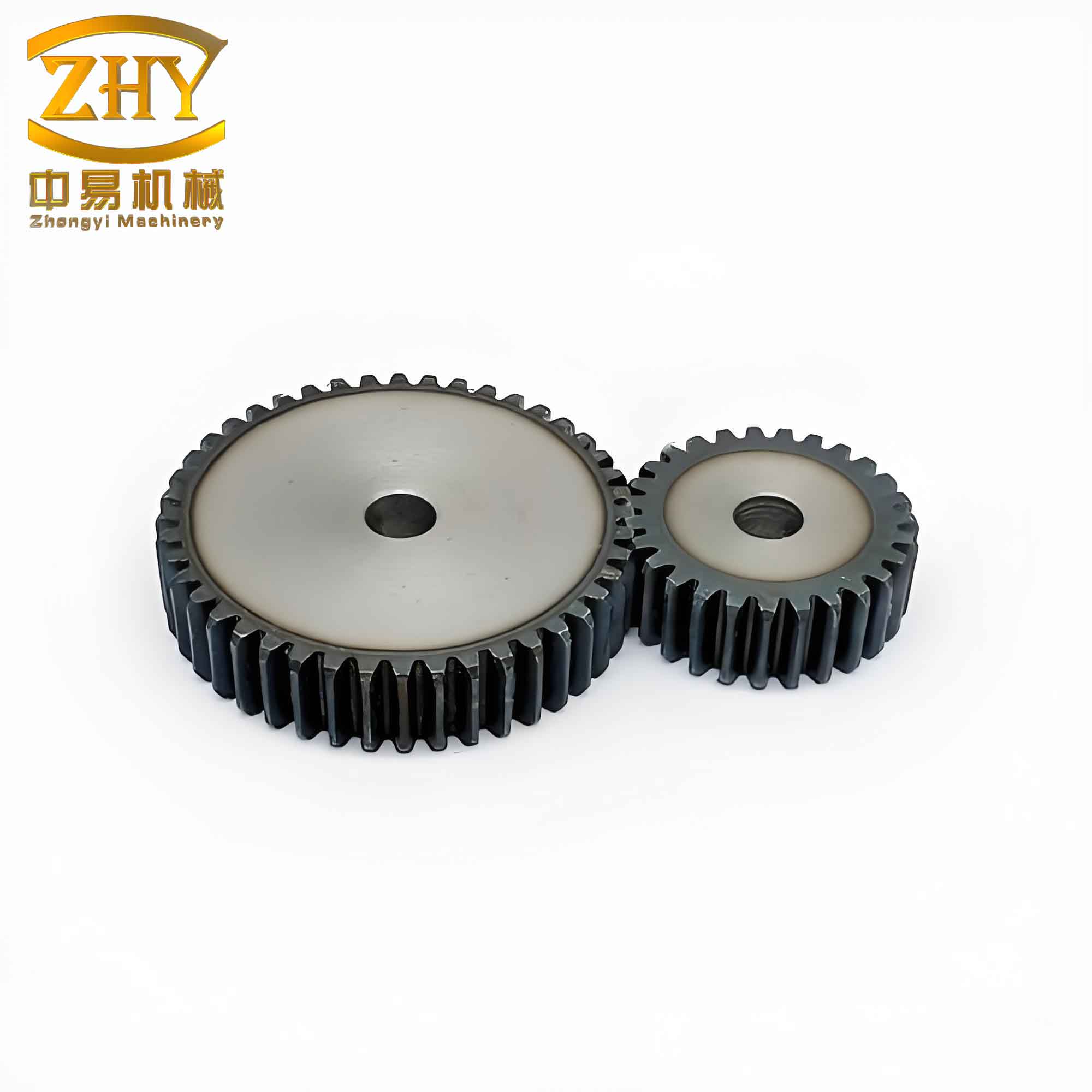
Figure 1 illustrates a typical straight spur gear used in this study.
4. Experimental Setup and Simulation Parameters
The cold precision forging process for straight spur gears was simulated using the finite element software DEFORM-3D. The gear parameters are listed in Table 2.
| Parameter | Value |
|---|---|
| Module, \(m\) | 3 mm |
| Number of teeth, \(z\) | 19 |
| Face width, \(B\) | 28 mm |
| Billet material | 45 steel (AISI 1045) |
| Friction coefficient (Coulomb) | 0.12 |
| Simulation model | 1/4 symmetry (tooth sector) |
| Upper die speed | 10 mm/s (first stage) |
| Core punch speed | 10 mm/s (second stage) |
| Initial billet dimensions | Diameter: 60 mm, Height: 50 mm |
The die assembly consisted of an upper die, lower die, outer die, and a core punch. The upper die had a nested protrusion with a stepped profile to promote radial flow. The core punch featured a rounded tip (radius 3 mm) to avoid cutting the material. A floating die mechanism was employed to allow the outer die to move with the workpiece during the initial compression, reducing friction. The simulation was run under isothermal conditions (room temperature) with the workpiece assumed to be rigid-plastic.
5. Results and Analysis
The simulation results for the proposed two-stage forging of straight spur gears are presented in terms of forming load versus time. Table 3 summarizes the peak loads recorded during each stage.
| Stage | Peak Load (MN) | Time at Peak (s) |
|---|---|---|
| First stage (upper die) | 1.84 | 14.7 |
| Second stage (core punch) | 0.71 | 24.4 |
| Total maximum (any stage) | 1.84 | – |
For comparison, the conventional flat die forging of the same straight spur gears required a peak load of 4.86 MN, while using a simple nested upper die reduced it to 4.54 MN. The proposed segmented process reduced the maximum load by over 60% compared to the conventional method. This remarkable reduction is primarily due to the enhanced radial flow during the core punch stage, which allows the tooth cavity to be filled at a much lower axial force.
Figure 2 shows the load–time curve for the upper die during the first stage. The load increases gradually as the material deforms and reaches a plateau when the billet attains the gear width. The core punch load (Figure 3) is significantly lower because the material only needs to be displaced radially into the remaining unfilled tooth spaces.
| Step | Time (s) | Upper Die Load (MN) | Core Punch Load (MN) |
|---|---|---|---|
| 0 | 0 | 0 | 0 |
| 10 | 5.8 | 0.73 | – |
| 20 | 11.6 | 1.47 | – |
| 30 | 14.7 | 1.84 | – |
| 40 | 17.4 | 1.38 | 0 |
| 50 | 23.2 | 0.10 | 0.32 |
| 60 | 24.4 | 0.05 | 0.71 |
| 70 | 29.0 | 0.02 | 0.40 |
The effective strain distribution at the end of forging was examined. The maximum effective strain occurred at the tooth root, reaching about 2.8. The material flow pattern showed that the radial velocity component dominated during the core punch stage, confirming the effectiveness of the divided flow principle. The stress state in the die was also analyzed; the maximum tensile stress in the outer die was below 800 MPa, well within the safe range for high-strength tool steel.
6. Discussion
Our results demonstrate that the segmented forging process significantly reduces the forming pressure for straight spur gears. The key innovation lies in the combination of a nested upper die and a subsequent core punch, which promotes material flow primarily in the radial direction during the final filling stage. This approach not only lowers the load but also improves die life by reducing the peak stress on the die cavity. Furthermore, the floating die mechanism reduces friction, contributing to a more uniform deformation. Compared to earlier divided flow methods that use a central hole or axial relief, our process requires no pre-forming of the billet and can be applied directly to solid cylindrical blanks.
One limitation of the current study is that it is based solely on numerical simulations. Experimental validation on a hydraulic press is underway. However, the simulation methodology using DEFORM-3D has been widely validated for cold forging applications, and the trends observed are consistent with plastic theory.
We also note that the material properties play a crucial role. For the 45 steel used here, the strain-hardening exponent \(n=0.15\) leads to moderate work hardening. For materials with higher hardening, the forming force might increase, but the relative benefit of the segmented process should remain similar.
7. Conclusion
We have developed an optimized cold precision forging process for straight spur gears that substantially reduces the forming force. The two-stage method – first using a nested upper die to compress the billet to the required width, then a core punch to drive radial flow into the tooth cavity – achieves a maximum load of only 1.84 MN, compared to 4.86 MN for conventional forging. This reduction of nearly 62% makes it feasible to forge large-module straight spur gears on standard 200-ton presses. The process also minimizes die stress and improves filling quality. Future work will include experimental trials and optimization of the punch geometry and lubrication conditions. The results of this study provide a practical pathway for the efficient cold forging of straight spur gears with enhanced die life and lower energy consumption.
Note: All data presented are based on DEFORM-3D simulations. Material properties and boundary conditions correspond to 45 steel under cold forging conditions.