
I conducted a comprehensive numerical and experimental study on the temperature field characteristics of straight spur gears with a high contact ratio, which are critical components in helicopter transmission systems. These gears are typically lubricated and cooled via oil jet injection, and their temperature behavior directly impacts operational lifespan and reliability. In this work, I developed a computational fluid dynamics-based model to simulate the temperature field of high contact ratio straight spur gears under oil jet lubrication. I employed the Volume of Fluid method for multiphase flow modeling and the Multiple Reference Frame technique to account for gear rotation. I systematically analyzed the effects of lubricating oil parameters, operating conditions, and gear geometric parameters on tooth surface temperature and convective heat transfer coefficients. I validated the simulation results through experimental testing on a CL-100 gear testing machine. The results confirm that significant trends in the gear temperature field are accurately captured by the CFD model, with high contact ratio straight spur gears exhibiting higher temperatures compared to standard spur gears, especially under increased load conditions.
Introduction
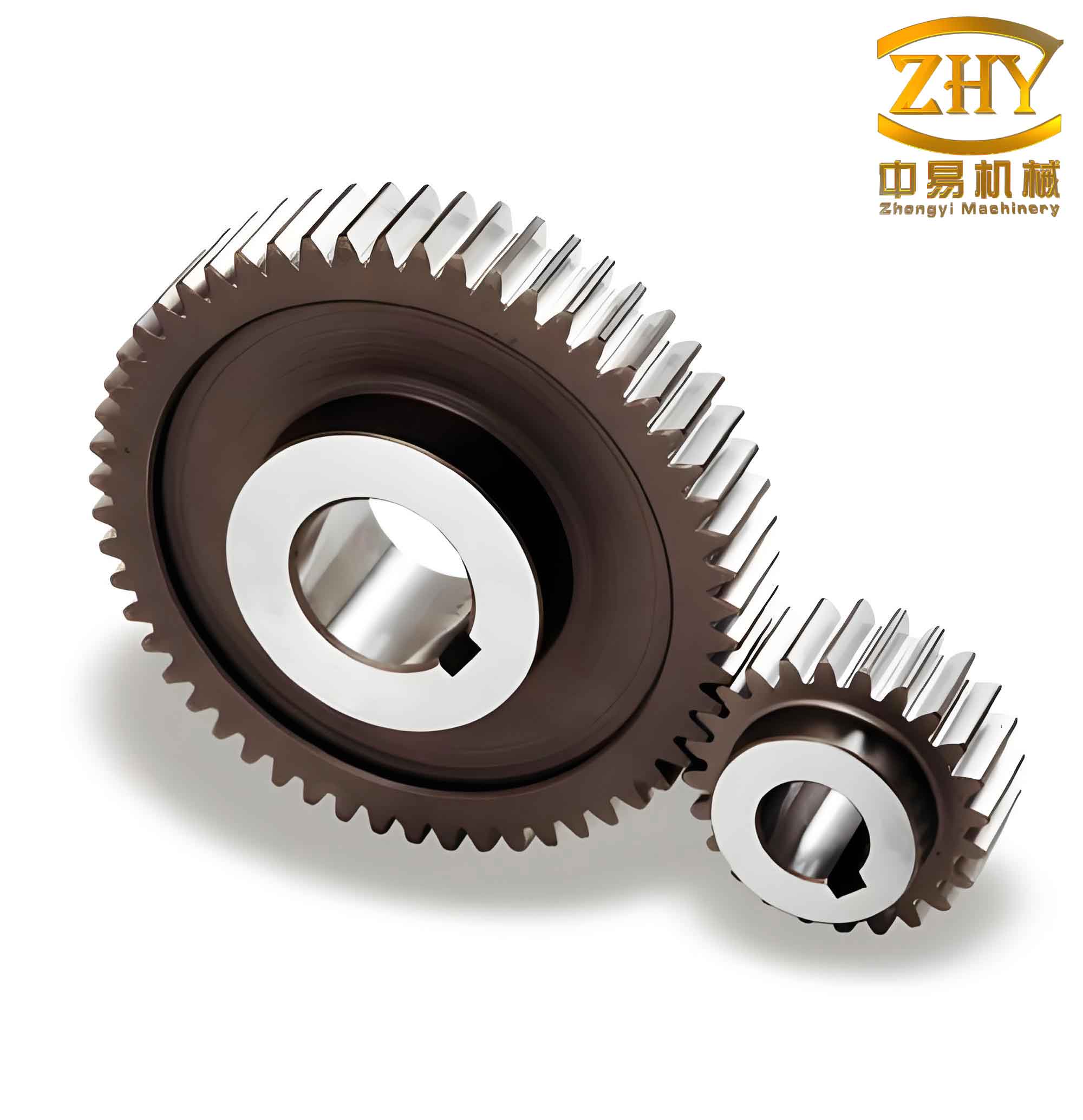
High contact ratio straight spur gears are characterized by a contact ratio exceeding 2. Unlike standard spur gears, these gear pairs always maintain at least two pairs of teeth in mesh during transmission, which increases the total length of the contact line and reduces the average load per unit length, thereby enhancing transmission safety and load capacity. During operation, power losses in high contact ratio straight spur gears are dissipated as heat. Inadequate lubrication and cooling can lead to excessive temperatures, causing failures such as tooth surface scuffing. In aerospace applications, these straight spur gears often operate under high-speed and heavy-load conditions, making them particularly susceptible to thermal failure. Therefore, I identified a critical need to conduct thermal-fluid coupling analysis on these components to study tooth surface temperature distribution, which has significant implications for improving cooling performance, heat transfer characteristics, transmission efficiency, and overall reliability.
Oil jet lubrication is the preferred method for cooling straight spur gears in aviation transmissions. The effectiveness of this cooling system is typically evaluated using the steady-state tooth surface temperature and convective heat transfer coefficient. In recent years, researchers have increasingly employed CFD methods to analyze gear temperature fields. For example, Ren et al. used ANSYS Workbench to simulate steady-state temperature fields of spur gears under various rotational speeds. Ji conducted simulations of herringbone gear temperature fields under oil jet lubrication and dry friction conditions, using infrared thermography for measurement. Yang studied temperature field distribution in high-speed train traction gear systems based on friction and Hertz contact theories. Peng performed steady-state temperature analysis on a helicopter main reducer gear, measuring surface temperatures under different torque, speed, and oil temperature conditions using infrared cameras. Bao et al. applied the MRF model for steady-state temperature simulation of splash-lubricated gearboxes, analyzing effects of rotational speed, immersion depth, and oil viscosity. Liao developed a coupled simulation approach for gearbox heat flow and power loss, analyzing oil distribution and temperature fields. Xiang constructed thermal network models for electric vehicle differential gearboxes. Gao established thermal-fluid coupling models for high-speed train gearboxes. Shi et al. calculated frictional heat flux and convective heat transfer coefficients based on gear tribology and Hertz theory. Yi et al. used micro-thermocouples to measure real-time gear surface temperatures under wide operating ranges. Li et al. developed finite element models to simulate frictional heating during gear meshing and conducted thermal experiments for validation.
Building upon these foundations, I employed CFD methods to perform thermal-fluid coupled simulations of high contact ratio straight spur gears under oil jet lubrication. I calculated gear surface temperature and convective heat transfer coefficient distributions and investigated the influence of lubricating oil parameters, operating conditions, and gear geometric parameters. I conducted experimental validation of gear temperature using a CL-100 gear testing machine to confirm the reliability of the simulation results.
Theoretical Foundation
Governing Equations
The fluid flow within the gearbox, while complex, must satisfy the Navier-Stokes equations, including the conservation of mass, momentum, and energy:
$$ \frac{\partial \rho_f}{\partial t} + \nabla(\rho_f \mathbf{u}) = 0 $$
$$ \frac{\partial \rho_f u_i}{\partial t} + \nabla(\rho_f u_i \mathbf{u}) = \nabla(\mu \text{grad} u_i) – \frac{\partial p}{\partial x_i} + S_i $$
$$ \frac{\partial (\rho_f T)}{\partial t} + \nabla(\rho_f \mathbf{u} T) = \nabla\left(\frac{k_f}{C_p} \text{grad} T\right) + S_T $$
where \( i = 1,2,3 \); \( t \) is time (s); \( u_i \) are velocity components; \( \mathbf{u} \) is the velocity vector (m/s); \( \mu \) is dynamic viscosity (Pa·s); \( p \) is pressure (Pa); \( S_i \) is the generalized source term (kg/(m2·s2)); \( \rho_f \) is fluid density (kg/m3); \( T \) is temperature (K); \( k_f \) is thermal conductivity (W/(m·K)); \( C_p \) is specific heat capacity (J/(kg·K)); and \( S_T \) is the viscous dissipation term (W).
Volume of Fluid Model
I used the VOF model in Fluent to track the oil-air interface. The sum of volume fractions for all phases in each control volume equals unity:
$$ \alpha_{\text{air}} + \alpha_{\text{oil}} = 1 $$
where \( \alpha_{\text{air}} \) and \( \alpha_{\text{oil}} \) are the volume fractions of air and oil, respectively.
Gear Heat Generation Calculation
The power losses due to friction directly affect the temperature characteristics. Using the Anderson-Loewenthal method, I calculated the average rolling power loss \( P_r \), average sliding power loss \( P_s \), and windage power loss \( P_w \):
$$ P_r = 90000 \cdot \overline{V}_t \cdot \overline{h} \cdot b \cdot e_p $$
$$ P_s = f \cdot \overline{F}_n \cdot \overline{V}_s / 1000 $$
$$ P_w = C \left(1 + 2.3 \frac{b}{R}\right) \rho_{\text{eq}}^{0.8} n^{2.8} R^{4.6} \mu_{\text{eq}}^{0.2} $$
Where \( \overline{V}_t \) and \( \overline{V}_s \) are mean rolling and sliding velocities (m/s), \( \overline{h} \) is oil film thickness (m), \( b \) is tooth width (m), \( e_p \) is the contact ratio, \( f \) is the friction coefficient, \( \overline{F}_n \) is the mean normal load (N), \( C \) is a constant (2.04×10⁻⁸), \( R \) is the pitch circle radius (m), \( \rho_{\text{eq}} \) is equivalent density of the oil-air mixture (kg/m3), \( n \) is rotational speed (r/min), and \( \mu_{\text{eq}} \) is equivalent dynamic viscosity (Pa·s). The total power loss \( Q \) is:
$$ Q = P_s + P_r + P_w $$
The heat flux is distributed between the driving and driven gears using a thermal distribution coefficient \( \gamma \):
$$ Q_1 = \gamma Q $$
$$ Q_2 = (1 – \gamma) Q $$
where \( \gamma = \frac{k_{s1} \rho_1 C_{p1} v_1}{k_{s1} \rho_1 C_{p1} v_1 + k_{s2} \rho_2 C_{p2} v_2} \), \( k_s \) is thermal conductivity (W/(m·K)), \( \rho \) is material density (kg/m3), and \( v \) is tangential velocity at the mesh point (m/s).
CFD Analysis Model
Parameters and Conditions
The geometric parameters and operating conditions for the straight spur gears are summarized in Table 1. The material properties of the gear are listed in Table 2, and the lubricating oil properties are shown in Table 3.
| Parameter | Large Gear (Driving) | Small Gear (Driven) |
|---|---|---|
| Normal Module \( m_n \) (mm) | 3.25 | 3.25 |
| Number of Teeth \( z \) | 32 | 25 |
| Face Width \( b \) (mm) | 16 | 16.5 |
| Addendum Modification Coefficient \( \xi \) | -0.19 | -0.14 |
| Pressure Angle \( \alpha_i \) (degrees) | 20 | 20 |
| Addendum Coefficient \( h_a^* \) | 1.32 | 1.32 |
| Clearance Coefficient \( c^* \) | 0.25 | 0.25 |
| Rotational Speed \( n \) (r/min) | 1500 | 1920 |
| Load Level | 9 | 9 |
| Contact Ratio | 2.2 | 2.2 |
| Material | Thermal Conductivity \( k_s \) (W/(m·K)) | Specific Heat \( C_p \) (J/(kg·K)) | Density \( \rho \) (kg/m3) |
|---|---|---|---|
| 20CrMnMoA | 46 | 470 | 7850 |
| Oil Type | Density at 15.6°C \( \rho_{\text{oil}} \) (kg/m3) | Kinematic Viscosity at 37.8°C \( \mu_{\text{oil}}’ \) (mm2/s) | Kinematic Viscosity at 98.9°C \( \mu_{\text{oil}}’ \) (mm2/s) |
|---|---|---|---|
| Shell 555 | 993 | 29 | 5.4 |
Computational Model and Mesh
To accurately simulate gear rotation and surrounding fluid motion, I used the MRF method, which transforms the flow equations into a rotating coordinate system. The rotating domain and stationary gear solid are coupled numerically through interface boundaries. The rotational speeds for the driving and driven gears were set to 1500 r/min and 1920 r/min, respectively. I generated a non-structured tetrahedral mesh for the complex geometry, simplifying small features like chamfers. The volumetric heat source values applied to the gear friction surfaces are shown in Table 4.
| Heat Generation Surface | Volumetric Heat Source (W/m3) |
|---|---|
| Driving Gear Mesh Surface | 3.65 × 10⁹ |
| Driven Gear Mesh Surface | 4.00 × 10⁹ |
Boundary Conditions
The boundary conditions used in the simulation are listed in Table 5. The oil jet inlet was set as a velocity inlet at 40 m/s, and the outlet as a pressure outlet at 1 atm. The gearbox wall was subjected to natural convection with a heat transfer coefficient of 50 W/(m2·K). The ambient temperature and initial gear temperature were set to 26.85°C, with initial oil temperature of 60°C.
| Boundary | Name | Type |
|---|---|---|
| Oil Inlet | inlet | velocity-inlet |
| Outlet | outlet | pressure-outlet |
| Driving Gear | pinion | wall |
| Driven Gear | gear | wall |
| Oil Pipe | youguan | wall |
| Rotating Domain 1 | volume1 | wall |
| Rotating Domain 2 | volume2 | wall |
| Top Cover | top | wall |
| Gearbox Wall | wall | wall |
Simulation Results and Parameter Analysis
Temperature Field Distribution
I observed that the temperature distribution on both the driving and driven gear surfaces was symmetric about the mid-point of the face width, with higher temperatures in the middle and decreasing towards the ends. This is due to better heat dissipation at the gear ends. The highest tooth temperature appeared near the addendum region at the mesh surface, where sliding friction is most pronounced. The tooth root area also showed elevated temperatures due to limited oil access. The gear web exhibited the lowest temperatures. The convective heat transfer coefficient on the driving gear surface was lower than on the driven gear, consistent with the lower rotational speed of the driving gear. The heat transfer coefficient increased with radius on the gear end faces. The mesh region had the highest oil content, leading to the maximum local heat transfer coefficient.
Influence of Lubricating Oil Parameters
Oil Temperature: I set the oil temperature from 40°C to 90°C. As oil temperature increased, the gear temperature increased linearly. This is because higher oil temperature increases the initial system energy and reduces oil viscosity, which increases sliding losses. The convective heat transfer coefficient increased with oil temperature due to lower viscosity, improving heat dissipation. However, the net effect was a rise in gear bulk temperature.
Oil Flow Rate: I varied the oil flow rate from 0.44 L/min to 2.64 L/min. At the lowest flow rate (0.44 L/min), gear temperature was highest. Increasing the flow rate reduced the gear temperature due to enhanced convective heat transfer. However, beyond 1.76 L/min, the temperature reduction rate slowed, indicating that excessive oil flow can lead to additional parasitic power losses. The convective heat transfer coefficient increased with flow rate.
Influence of Operating Parameters
Rotational Speed: I set the driving gear speed from 1000 to 3500 r/min. The gear temperature increased with speed up to 2500 r/min due to higher sliding velocities and heat generation. When speed increased from 2500 to 3000 r/min, a slight temperature decrease was observed as the reduced contact time allowed for more effective cooling. The convective heat transfer coefficient varied with speed and was consistently higher on the driven gear.
Load: I tested load levels from 1 to 9. As the load increased, both maximum and minimum gear temperatures increased significantly. This is due to the increase in normal load and friction coefficient, leading to higher frictional heat. The effect of load on temperature was more pronounced than that of speed. The temperature rise rate diminished at higher load levels due to increasing counteracting factors.
Influence of Gear Geometric Parameters
Tooth Width: Increasing the tooth width generally decreased the tooth surface temperature. Although wider teeth generate more frictional heat, the larger surface area for heat dissipation has a more significant cooling effect.
Pressure Angle: I tested pressure angles of 14°, 17°, 20°, and 23°. Increasing the pressure angle reduced the maximum and minimum gear temperatures. This is because a larger pressure angle reduces the frictional heat generation during meshing.
Contact Ratio: I varied the addendum coefficient to achieve contact ratios from 1.73 to 2.21. Increasing the contact ratio increased the gear temperature for both driving and driven straight spur gears. However, the convective heat transfer coefficient also increased with contact ratio due to higher mean tooth height and Reynolds number. For the driven gear at certain points, the increase in heat transfer offset the heat generation, leading to a slight temperature decrease.
Experimental Validation
Experimental Setup
I conducted temperature tests using a CL-100 gear testing machine to measure the real-time temperature of straight spur gears. I installed type-K thermocouples into small holes drilled near the tooth surface, angled from the gear end face. The signal wires were routed through the hollow shaft to a wireless data logger mounted in a sealed box at the shaft end. I heated the lubricating oil to 60°C and injected it at 40 m/s from the mesh inlet side. The computer monitoring system recorded spindle speed, torque, oil temperature, gear temperature, and operating time.
Results and Comparison
I observed that gear temperature increased rapidly during the first 10 minutes of operation, then stabilized, reaching steady-state conditions within 25 to 30 minutes. I compared the simulated and experimental steady-state temperatures under various oil temperatures (60°C and 90°C) and load levels.
| Load Level | Driving Gear Temperature (°C) | Driven Gear Temperature (°C) | ||
|---|---|---|---|---|
| Simulation | Experiment | Simulation | Experiment | |
| 1 | 72.5 | 70.1 | 68.2 | 66.5 |
| 3 | 78.4 | 76.8 | 74.1 | 72.9 |
| 5 | 84.8 | 83.5 | 80.5 | 79.2 |
| 7 | 91.6 | 90.1 | 87.3 | 86.0 |
| 9 | 98.2 | 97.0 | 93.8 | 92.5 |
| Load Level | Driving Gear Temperature (°C) | Driven Gear Temperature (°C) | ||
|---|---|---|---|---|
| Simulation | Experiment | Simulation | Experiment | |
| 1 | 95.1 | 92.8 | 90.4 | 88.5 |
| 3 | 101.3 | 99.5 | 96.7 | 95.0 |
| 5 | 108.0 | 106.2 | 103.5 | 101.8 |
| 7 | 115.2 | 113.5 | 110.6 | 108.9 |
| 9 | 122.1 | 120.8 | 117.5 | 116.0 |
Both simulation and experimental results demonstrate that the maximum temperature of high contact ratio straight spur gears increases with load. The simulation results closely match the experimental data, with errors decreasing at higher loads. This validates the CFD modeling approach for predicting the temperature field of these straight spur gears.
Comparison of High Contact Ratio and Standard Straight Spur Gears
I also compared the temperature of high contact ratio straight spur gears (contact ratio 2.2) with standard straight spur gears (contact ratio 1.73) under identical test conditions.
| Load Level | Driving Gear Max Temperature (°C) | Driven Gear Max Temperature (°C) | ||
|---|---|---|---|---|
| HCR (2.2) | Standard (1.73) | HCR (2.2) | Standard (1.73) | |
| 1 | 70.1 | 67.5 | 66.5 | 64.2 |
| 3 | 76.8 | 73.1 | 72.9 | 69.5 |
| 5 | 83.5 | 78.8 | 79.2 | 75.0 |
| 7 | 90.1 | 84.6 | 86.0 | 80.8 |
| 9 | 97.0 | 90.5 | 92.5 | 86.4 |
| Load Level | Driving Gear Max Temperature (°C) | Driven Gear Max Temperature (°C) | ||
|---|---|---|---|---|
| HCR (2.2) | Standard (1.73) | HCR (2.2) | Standard (1.73) | |
| 1 | 92.8 | 89.5 | 88.5 | 85.2 |
| 3 | 99.5 | 95.1 | 95.0 | 90.8 |
| 5 | 106.2 | 100.8 | 101.8 | 96.5 |
| 7 | 113.5 | 106.8 | 108.9 | 102.4 |
| 9 | 120.8 | 113.2 | 116.0 | 108.6 |
The experimental data clearly show that high contact ratio straight spur gears consistently operate at higher temperatures than standard straight spur gears under the same conditions. This temperature difference becomes more pronounced as the load increases. This phenomenon is attributed to the increased frictional heat generation associated with the longer contact paths inherent in high contact ratio straight spur gears.
Conclusion
I successfully developed a CFD model using the MRF method for thermal-fluid coupled temperature field simulation of high contact ratio straight spur gears under oil jet lubrication. The maximum gear surface temperature was found at the mesh surface near the tooth addendum, with a symmetric distribution along the face width. The convective heat transfer coefficient was lower on the driving gear compared to the driven gear and increased with radial distance on the gear end faces. Parameter studies revealed that gear temperature increases with load and rotational speed, though the rate of increase diminishes at higher values. Increasing oil flow rate, tooth width, and pressure angle reduces the temperature, while increasing oil temperature and contact ratio raises the temperature. I validated the finite element simulation method through experiments on a CL-100 gear testing machine. The results confirmed the general trend of increasing temperature with load for straight spur gears. Critically, I demonstrated that high contact ratio straight spur gears experience higher tooth surface temperatures than standard straight spur gears, and this temperature differential becomes more significant under higher loads. These findings provide valuable insights for the thermal design and lubrication optimization of high contact ratio straight spur gear systems in aerospace applications.