
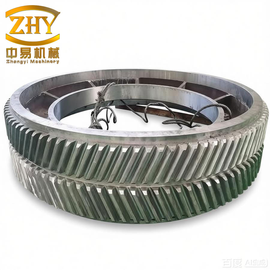
In the field of high-power transmission systems, such as those found in aerospace and marine applications, the herringbone gear stands out due to its exceptional load-carrying capacity, smooth operation, and inherent axial force cancellation. My work focuses on addressing a critical challenge in these systems: the sensitivity of high contact ratio herringbone gears to manufacturing errors and tooth deformation. Through my research, I have developed a comprehensive optimization framework for parabolic tooth modification, leveraging tooth contact analysis and multi-objective genetic algorithms to significantly enhance the meshing performance of herringbone gears.
The foundation of my approach lies in a robust analytical model. I treat a herringbone gear as two mirror-symmetric helical gears with opposite helix angles. To improve economic efficiency and simplify the manufacturing process, I apply all modifications exclusively to the pinion. The core modification strategy involves a parabolic profile in both the tooth profile and lead directions. For the profile modification, I replace the standard straight cutting edge of the rack-cutter with a parabolic curve. This design allows the gear tooth to effectively eliminate interference during the initial and final engagement phases, thereby reducing mesh stiffness fluctuations.
The mathematical representation of the rack-cutter profile is established in a local coordinate system. For the left-side tooth flank of the rack, the coordinates in the \(S_a\) coordinate system are expressed as:
$$
\mathbf{r}_a(u_i) = \begin{bmatrix} a_i u_i^2 \\ -u_i \\ 0 \\ 1 \end{bmatrix}
$$
where \(a_i\) is the profile parabola coefficient and \(u_i\) is the parameter along the profile direction. I then transform this equation into the end-face coordinate system \(S_c\) of the rack, which is rigidly connected to the tool, using a series of coordinate transformations that account for the helix angle \(\beta_c\) and the rack length parameter \(l_i\). The resulting tooth surface equation of the generating tool is given by:
$$
\mathbf{r}_c(u_i, l_i, \phi_i) = \mathbf{M}_{cb} \cdot \mathbf{M}_{ba} \cdot \mathbf{r}_a(u_i, l_i)
$$
This is coupled with the equation of meshing to form a complete surface representation. I use the same principle for the tooth lead modification, employing a symmetric parabolic cylinder along the helix with the midpoint of the tooth width as the vertex. The normal modification amount \(y\) is defined by a simple quadratic function:
$$
y = a^* x^2
$$
This dual parabolic modification strategy is particularly effective for herringbone gears because it can compensate for non-uniform load distribution across the tooth width, a common problem caused by inevitable alignment errors.
A significant portion of my research is dedicated to the Tooth Contact Analysis (TCA) of herringbone gears. I developed a computer simulation to visualize the contact paths and transmission errors under realistic operating conditions. The core of the TCA is the simulation of point contact between the two tooth flanks, which replaces the theoretical line contact when installation errors like center distance deviation \(\Delta E\), axial offset \(\Delta L\), and axis parallelism error \(\Delta \gamma\) are introduced. The kinematic condition for continuous tangential contact is mathematically defined by two vector equations that must have a common solution in the fixed coordinate system:
$$
\mathbf{r}_g^{(1)}(u_1, l_1, \phi_1) = \mathbf{r}_g^{(2)}(u_2, l_2, \phi_2)
$$
$$
\mathbf{n}_g^{(1)}(u_1, l_1, \phi_1) = \mathbf{n}_g^{(2)}(u_2, l_2, \phi_2)
$$
Here, superscripts (1) and (2) denote the driving and driven gears, respectively. By solving these equations for a sequence of pinion rotation angles \(\phi_1\), I can compute the corresponding driven gear rotation \(\phi_2\) and the instantaneous contact points. The transmission error, a key indicator of gear noise and vibration, is defined as the deviation of the actual rotation from the theoretical one:
$$
\Delta \phi_2 = \phi_2 – \phi_2^{(0)} – \left( \phi_1 – \phi_1^{(0)} \right) \frac{z_1}{z_2}
$$
For herringbone gears, which consist of two helical gear halves, I perform the TCA separately for each side. A critical innovation in my model is the handling of synchronization errors between the left and right tooth flanks. To simulate the effect of manufacturing tolerances, I input a phase difference \(\Delta \phi\) for the pinion rotations of the two sides:
$$
\phi_L = \phi_R – \Delta \phi
$$
where \(\Delta \phi = \sum e / (r_b \cos \beta_b)\), \(\sum e\) is the relative manufacturing error, \(r_b\) is the base radius, and \(\beta_b\) is the base helix angle. This methodology allows me to accurately predict load imbalances and edge contact that are common in high-contact-ratio herringbone gears.
The ultimate goal of my work is to optimize the modification parameters to achieve the best possible meshing performance. To this end, I formulated a multi-objective optimization problem using the elitist Non-dominated Sorting Genetic Algorithm (NSGA-II). This powerful algorithm is particularly suitable for my problem because it can find a set of Pareto-optimal solutions, avoiding the pitfalls of local convergence that plague single-objective methods. I defined two objective functions to be minimized:
First objective function: Minimize the fluctuation of the geometric transmission error to ensure smooth operation.
$$
\min f_1 = \min\left( \max(\Delta \phi_2) – \min(\Delta \phi_2) \right)
$$
Second objective function: Maximize the number of contact points on the left-side tooth flank of the herringbone gear (which I convert to a minimization problem) to reduce load imbalance.
$$
\min f_2 = \min\left( -PN \right)
$$
The design variables for the optimization are the profile parabola coefficient \(\alpha_1\), the profile modification vertex parameter \(u_{01}\), and the lead parabola coefficient \(\alpha^*\). The specific parameters for the gear pair used in my study are summarized in the table below:
| Parameter | Pinion / Gear |
|---|---|
| Number of teeth | 23 / 231 |
| Module (mm) | 4.051 |
| Pressure angle (°) | 20 |
| Helix angle (°) | 34.096 |
| Face width (mm) | 112.51 |
| Center distance error (mm) | 0.04 |
| Parallelism error (arc min) | 0.01 |
The NSGA-II algorithm was run with a population size of 108 for 100 generations. The evolution of the feasible solutions is quite instructive. In the 10th generation, the left-side tooth flank of the herringbone gears often had zero contact points, indicating severe load imbalance. By the 60th generation, the number of contact points on the left side had mostly increased to 3, although the transmission error fluctuation remained relatively unchanged. By the 100th generation, the algorithm had successfully optimized both objectives, with the transmission error fluctuation falling to the range of 0 to 1.25 arc seconds and the number of left-side contact points stabilizing at 3 or even 4. The final optimal solution I selected is presented in the following table.
| Parameter | Before Optimization | After Optimization |
|---|---|---|
| Profile parabola coefficient \(\alpha_1\) | 0.005 | 0.00637 |
| Profile vertex position \(u_{01}\) (mm) | -0.01 | -0.0329 |
| Lead parabola coefficient \(\alpha^*\) | 2E-11 | 4E-6 |
| Transmission error fluctuation (arc sec) | 1.27 | 0.332 |
| Left-side contact points count | 0 | 3 |
The performance improvement is dramatic. Before optimization, the herringbone gears suffered from severe load imbalance: when the right flank meshed, the left flank experienced no contact at all, and the transmission error curve was discontinuous. This is a recipe for high noise and vibration. After optimization, the contact pattern on the left flank became regular, with multiple simultaneous contact points, effectively sharing the load with the right flank. Furthermore, the transmission error curve transformed into a smooth, continuous parabolic shape. This parabolic form, a direct result of the lead modification, is highly beneficial for reducing gear noise as it allows for gradual tooth entry and exit, minimizing mesh impact. The reduction in transmission error fluctuation from 1.27 to 0.332 arc seconds is substantial.
To validate my simulation results, I conducted an experimental noise test on a high-speed gear test rig. I compared the air-borne noise levels of the original and optimized herringbone gears under load. Measurements were taken at six different points around the gearbox. The results, shown in the table below, provide definitive evidence of the success of my optimization method.
| Measurement Point | Before Optimization (dB) | After Optimization (dB) |
|---|---|---|
| Point 1 | 114.34 | 108.72 |
| Point 2 | 117.13 | 111.11 |
| Point 3 | 113.56 | 108.24 |
| Point 4 | 115.27 | 109.56 |
| Point 5 | 116.79 | 111.49 |
| Point 6 | 115.76 | 108.91 |
The noise reduction is consistent across all measurement points, showing a decrease of approximately 5 to 7 dB. This is a significant improvement, confirming that my optimization framework for herringbone gears not only improves theoretical contact patterns but also has a tangible effect in reducing vibration and noise in a real-world transmission system. The combination of parabolic profile modification and the Pareto-optimized lead modification effectively reduces the mesh impact and ensures a more uniform load distribution across the entire tooth flank of the herringbone gears.
In conclusion, my research has successfully demonstrated a powerful and systematic method for the modification optimization of high contact ratio herringbone gears. By integrating detailed tooth contact analysis that accounts for realistic installation errors with the robust multi-objective capabilities of the NSGA-II algorithm, I was able to identify a set of optimal parabolic modification coefficients. The results show that this approach effectively eliminates the load imbalance between the two helical flanks, transforms the transmission error into a smooth, low-amplitude curve, and yields a significant reduction in operational noise. This work provides a valuable theoretical and practical framework for the design of high-performance, low-noise herringbone gear transmissions for demanding applications.