
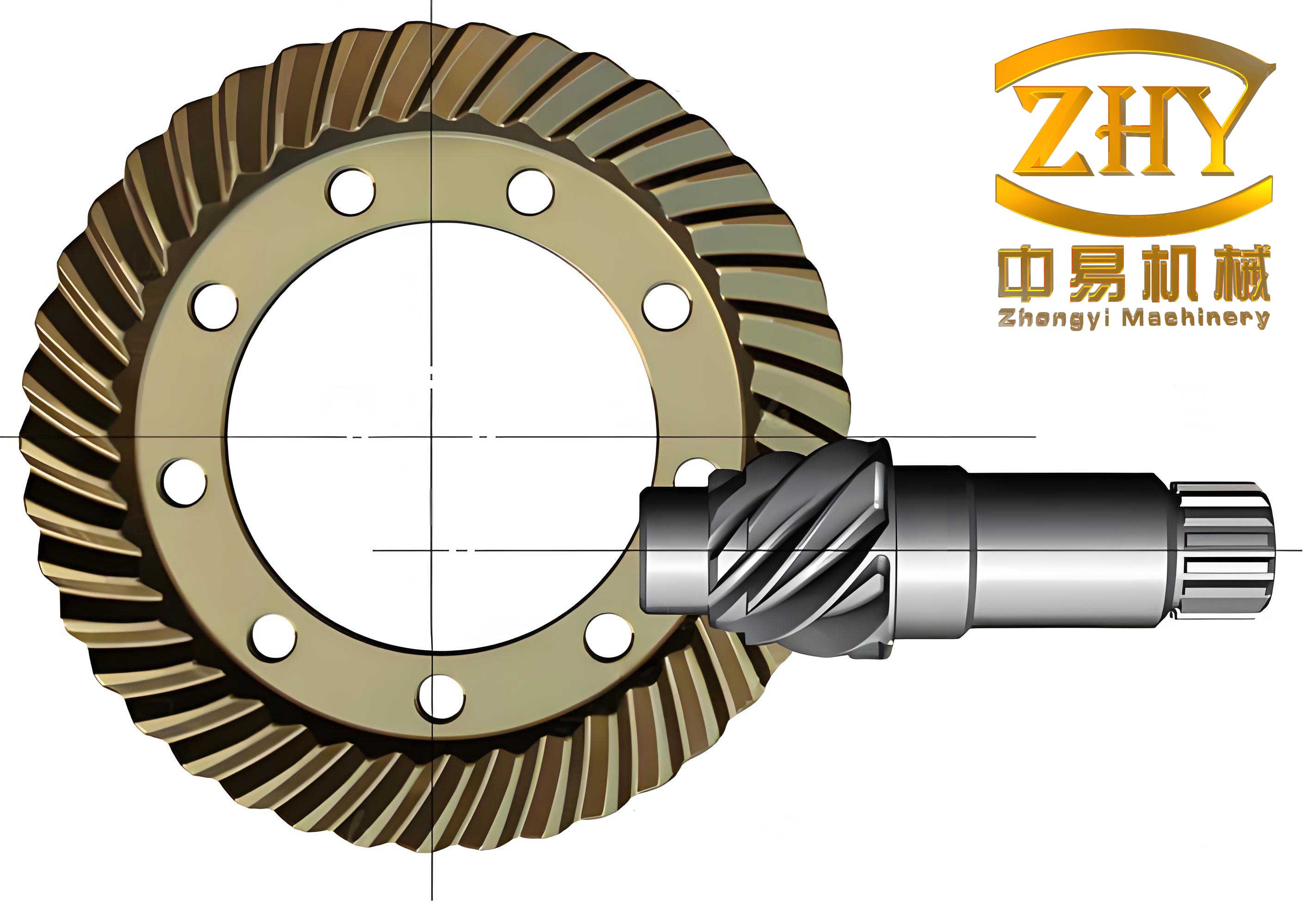
Hypoid gears are widely used in the main reducer of automobile drive axles because of their large transmission ratio, smooth operation, and strong load-carrying capacity. They are key components in the power transmission system of vehicles. With the continuous development of the automotive industry, the requirements for the meshing performance of hypoid gears have become increasingly stringent. Poor meshing performance not only increases the vibration and noise of the drive axle but also affects its reliability and safety. Therefore, improving the meshing performance of hypoid gears has significant practical value. The tooth surface contact pattern and transmission error are the two most critical indicators for evaluating the meshing performance of hypoid gears. In this thesis, a comprehensive optimization method for gear meshing performance is proposed, which simultaneously considers both the contact pattern and the transmission error. In addition, since installation errors are an important factor affecting the meshing performance of hypoid gears, the meshing performance under the action of installation errors is studied. By optimizing the machine tool settings, the sensitivity of the gear meshing performance to installation errors is reduced, so that the gear pair still maintains good meshing quality under certain assembly deviations.
The main research work of this thesis is organized as follows. First, based on the cutting principles of hypoid gears, the mathematical models of the cutting tools, the machine tool, and the tooth blank are established. According to the relative motion between the tooth blank and the tool during the cutting process, the tooth surface equations of the gear pair are derived by coordinate transformation. The tooth surface is discretized into a grid, and the tooth surface equations are solved using Matlab software to obtain the three-dimensional coordinates of the surface discrete points. The discrete points are then imported into SolidWorks software to build the three-dimensional geometric models of the hypoid gear pair.
Second, based on the tooth surface equations and the meshing principle, a gear meshing mathematical model is constructed. Through tooth contact analysis, the contact characteristics of the tooth surface are obtained, including the contact pattern and the transmission error curve. To solve the problems of edge contact, excessively large contact trace inclination angle, and discontinuous transmission error curve, an optimization method for gear meshing performance is proposed. The improved particle swarm optimization algorithm is employed to adjust the machine tool settings of the pinion. After optimization, the tooth surface contact pattern is located within the allowable region, the inclination angle of the contact trace is reduced, and the transmission error curve becomes continuous with intersections between adjacent curves.
Third, the installation errors are introduced into the gear meshing mathematical model. Four types of installation errors are considered: the axial error of the gear, the axial error of the pinion, the offset error, and the shaft angle error. By quantitatively varying the magnitude of each installation error, the sensitivity of the tooth surface contact pattern parameters to each type of installation error is studied. The results show that the offset error has the greatest influence on the contact pattern, while the gear axial error has the least influence. Based on the sensitivity differences, a comprehensive sensitivity model is established using a weighting method. The improved particle swarm optimization algorithm is used to minimize the comprehensive sensitivity by optimizing the machine tool settings. The results show that the optimized gear pair exhibits smaller contact pattern deviations under the same installation error conditions.
Finally, cutting experiments, tooth surface error measurement, and rolling tests are carried out for the hypoid gear pair before and after optimization. The experimental results confirm that the optimized gear pair has no edge contact, the contact pattern is distributed more reasonably on the tooth surface, and the transmission noise is reduced by 13.6% compared with the original gear pair. These results validate the feasibility and effectiveness of the proposed optimization methods.
1. Tooth Surface Equation of Hypoid Gears
The generation of the tooth surface of hypoid gears is a complex process that depends on the machine tool kinematics and the tool geometry. In this work, the gear is generated by the forming method, while the pinion is generated by the tilt method. The mathematical models of the tool and the machine tool are established based on the actual cutting process.
1.1 Gear Tooth Surface Equation
For the gear, the forming method is adopted, which means that the cradle and the workpiece do not rotate during cutting. The cutting edge rotates around the cutter axis to form a conical surface. In the cutter coordinate system, the position vector and unit normal vector of a point on the internal cutting edge are expressed as:
$$
\mathbf{r}_c =
\begin{bmatrix}
(r_d – u_c \sin \alpha_c)\cos\theta_c \\
(r_d – u_c \sin \alpha_c)\sin\theta_c \\
-u_c \cos\alpha_c \\
1
\end{bmatrix}
$$
$$
\mathbf{n}_c =
\begin{bmatrix}
\cos\alpha_c\cos\theta_c \\
\cos\alpha_c\sin\theta_c \\
-\sin\alpha_c
\end{bmatrix}
$$
where $r_d$ is the cutter tip radius, $u_c$ is the blade profile parameter, $\alpha_c$ is the blade pressure angle, and $\theta_c$ is the cutter rotation angle.
By transforming the cutter coordinate system to the gear blank coordinate system through the machine tool settings, the gear tooth surface can be expressed as:
$$
\mathbf{r}_m = \mathbf{M}_{mg}\mathbf{M}_{gc}\mathbf{r}_c
$$
$$
\mathbf{n}_m = \mathbf{L}_{mg}\mathbf{L}_{gc}\mathbf{n}_c
$$
where $\mathbf{M}_{mg}$ and $\mathbf{M}_{gc}$ are the transformation matrices, and $\mathbf{L}_{mg}$ and $\mathbf{L}_{gc}$ are the corresponding rotational matrices obtained by removing the last row and column.
The machine tool setting parameters of the gear used in this study are listed in Table 1.
| Parameter | Value |
|---|---|
| Cutter nominal diameter (mm) | 304.8 |
| Blade tip width (mm) | 3.81 |
| Blade pressure angle (°) | 22.30 |
| Blade edge radius (mm) | 1.90 |
| Machine root angle (°) | 70.32 |
| Horizontal cutter position (mm) | 79.66 |
| Vertical cutter position (mm) | 122.01 |
| Horizontal wheel position (mm) | -1.05 |
1.2 Pinion Tooth Surface Equation
The pinion is generated by the tilt method, where the cradle and the workpiece rotate simultaneously during cutting. The tool axis is tilted with respect to the cradle axis. The cutting process can be described by a series of coordinate transformations. The position vector of the cutting surface in the tool coordinate system is:
$$
\mathbf{r}_p =
\begin{bmatrix}
(r_x + u_p \sin \alpha_p)\cos\theta_p \\
(r_x + u_p \sin \alpha_p)\sin\theta_p \\
-u_p \cos\alpha_p \\
1
\end{bmatrix}
$$
where $r_x$ is the pinion cutter tip radius, $u_p$ is the blade profile parameter, $\alpha_p$ is the blade pressure angle, and $\theta_p$ is the cutter rotation angle.
The unit normal vector is:
$$
\mathbf{n}_p =
\begin{bmatrix}
\cos\alpha_p\cos\theta_p \\
\cos\alpha_p\sin\theta_p \\
-\sin\alpha_p
\end{bmatrix}
$$
The complete transformation from the tool coordinate system to the pinion blank coordinate system involves the tilt angle $i$, the swivel angle $j$, the radial cutter position $S_{r1}$, the cradle angle $q$, the vertical offset $E$, the bed offset $\Delta B$, the horizontal wheel position $\Delta A$, and the machine root angle $\gamma_2$. The total transformation can be written as:
$$
\mathbf{r}_w = \mathbf{M}_{wf}\mathbf{M}_{fu}\mathbf{M}_{uq}\mathbf{M}_{qr}\mathbf{M}_{rA}\mathbf{M}_{Ap}\mathbf{r}_p
$$
$$
\mathbf{n}_w = \mathbf{L}_{wf}\mathbf{L}_{fu}\mathbf{L}_{uq}\mathbf{L}_{qr}\mathbf{L}_{rA}\mathbf{L}_{Ap}\mathbf{n}_p
$$
During the generation process, the pinion tooth surface is the envelope of the family of cutter surfaces. The meshing equation between the generating gear and the pinion blank must be satisfied:
$$
\mathbf{n}_q \cdot \mathbf{v}_q = 0
$$
where $\mathbf{v}_q$ is the relative velocity between the cutter and the workpiece. By solving this equation, the blade parameter $u_p$ can be eliminated, and the pinion tooth surface is obtained as a function of the two parameters $\theta_p$ and $\phi_c$, where $\phi_c$ is the cradle rotation angle.
Table 2 lists the pinion machine tool settings before optimization.
| Parameter | Concave side | Convex side |
|---|---|---|
| Cutter tip diameter (mm) | 298.54 | 299.66 |
| Blade pressure angle (°) | 14.00 | 35.00 |
| Blade edge radius (mm) | 2.47 | 2.47 |
| Tilt angle (°) | 15.07 | 15.50 |
| Swivel angle (°) | 248.96 | 267.48 |
| Radial cutter position (mm) | 139.67 | 141.52 |
| Angular cutter position (°) | 55.64 | 47.11 |
| Machine root angle (°) | -2.00 | -3.59 |
| Horizontal wheel position (mm) | -4.34 | 5.94 |
| Bed offset (mm) | 34.79 | 50.96 |
| Vertical offset (mm) | 34.94 | 36.13 |
| Ratio of roll | 4.19 | 4.37 |
1.3 Tooth Surface Discretization and Solid Model
To obtain the three-dimensional geometric model, the tooth surface is divided into a grid of 5×9 points in the axial projection plane. The coordinates of the boundary points are determined from the blank parameters. For a point on the tooth surface, its projection onto the axial plane must satisfy the following relationship:
$$
x(P_0) = x(u,\theta)
$$
$$
y(P_0) = \sqrt{y^2(u,\theta) + z^2(u,\theta)}
$$
The nonlinear equations are solved using the Matlab solve function with initial values obtained from the geometric center of the tooth surface. The solution path is planned from the center point outward to ensure convergence.
The blank parameters of the hypoid gear pair are given in Table 3.
| Parameter | Pinion | Gear |
|---|---|---|
| Hand of spiral | Left | Right |
| Number of teeth | 9 | 39 |
| Face width (mm) | 59.25 | 54 |
| Spiral angle (°) | 48.36 | 36.54 |
| Offset (mm) | 35 | |
| Whole tooth height (mm) | 17.07 | 16.90 |
| Pitch angle (°) | 15.65 | 74.01 |
| Face cone angle (°) | 19.60 | 76.30 |
| Root cone angle (°) | 14.95 | 70.57 |
| Outer cone distance (mm) | 97.19 | 84.72 |
After solving the tooth surface equations, the point cloud data of the tooth surfaces are imported into SolidWorks, where they are fitted into surfaces. By combining these surfaces with the blank geometry and performing Boolean operations, a single tooth slot is created. The slot is then patterned around the blank according to the number of teeth to obtain the complete three-dimensional model of the hypoid gears.
2. Tooth Contact Analysis and Meshing Performance Optimization
2.1 Tooth Contact Analysis Theory
Tooth contact analysis (TCA) is performed to evaluate the meshing performance of hypoid gears without manufacturing physical prototypes. The gear pair is virtually assembled in a common coordinate system, as shown in the mathematical model. The gear and the pinion tooth surfaces are transformed into the assembly coordinate system. For a given contact point, the position vectors and unit normals of the two surfaces must be equal. The TCA equations are:
$$
\mathbf{r}_m^T = \mathbf{r}_w^T
$$
$$
\mathbf{n}_m^T = \mathbf{n}_w^T
$$
where $\mathbf{r}_m^T$ and $\mathbf{r}_w^T$ are the position vectors of the gear and pinion surfaces in the assembly coordinate system, and $\mathbf{n}_m^T$ and $\mathbf{n}_w^T$ are the corresponding unit normals.
By assigning a series of rotation angles to the pinion and solving the nonlinear equations, the contact points on both tooth surfaces are obtained. The collection of contact points forms the contact path. The contact ellipse at each point is determined from the relative principal curvatures and the elastic approach. The length of the major and minor axes of the contact ellipse can be calculated as:
$$
l_{\max} = \sqrt{\frac{2\delta}{K_{\min}}}
$$
$$
l_{\min} = \sqrt{\frac{2\delta}{K_{\max}}}
$$
where $\delta$ is the separation distance (typically 0.00635 mm), and $K_{\max}$ and $K_{\min}$ are the maximum and minimum relative curvatures.
The transmission error is defined as the difference between the actual rotation angle of the gear and the theoretical rotation angle:
$$
\Delta\varepsilon = \phi_w – \frac{z_1}{z_2}\phi_m
$$
where $z_1$ and $z_2$ are the number of teeth of the pinion and gear, respectively, and $\phi_m$ and $\phi_w$ are the rotation angles of the pinion and gear.
2.2 Initial Contact Characteristics
Based on the initial machine tool settings, the TCA results are obtained. The contact pattern on the gear convex side and the pinion concave side are calculated. The initial contact pattern shows several defects:
- Edge contact occurs at the tooth boundary.
- The inclination angle of the contact trace is too large (46.18°).
- The transmission error curve is discontinuous and does not intersect with adjacent curves.
These defects cause excessive vibration and noise, and reduce the load-carrying capacity of the gear pair. Therefore, an optimization procedure is necessary.
2.3 Optimization Model
Three objective functions are selected to characterize the meshing performance:
- Contact pattern area $S$.
- Inclination angle of the contact trace $\gamma$.
- Ordinate of the transmission error curve intersection $\delta$.
The optimization objective function is defined as:
$$
f(S,\gamma,\delta) = \varepsilon_1 \left|\frac{S – S_1}{S_1}\right| + \varepsilon_2 \left|\frac{\gamma – \gamma_1}{\gamma_1}\right| + \varepsilon_3 \left|\frac{\delta – \delta_1}{\delta_1}\right|
$$
where $S_1$, $\gamma_1$, and $\delta_1$ are the target values, and $\varepsilon_1$, $\varepsilon_2$, $\varepsilon_3$ are the weighting factors normalized to the required optimization accuracy.
The design variables are the principal curvatures $k_1$, $k_2$ and the geodesic torsion $k_3$ of the pinion cutting cone at the reference point. These parameters define the shape of the generating gear and directly determine the tooth surface geometry of the pinion. The search space is defined as:
$$
k_1 \in [(1-a_0)k_1^0, (1+a_0)k_1^0]
$$
$$
k_2 \in [(1-b_0)k_2^0, (1+b_0)k_2^0]
$$
$$
k_3 \in [(1-c_0)k_3^0, (1+c_0)k_3^0]
$$
where $a_0$, $b_0$, $c_0$ are scaling factors between 0.002 and 0.2, and $k_1^0$, $k_2^0$, $k_3^0$ are the initial curvature parameters.
The tooth contact pattern must not exceed the allowable region, which is obtained by shrinking the tooth boundary by a factor $H_i$ (typically 0.85 to 0.95). The constraint is that every contact ellipse endpoint must remain inside the allowable region.
2.4 Improved Particle Swarm Optimization
To solve the nonlinear optimization problem, an improved particle swarm optimization (PSO) algorithm is employed. The traditional PSO updates particle velocity and position as follows:
$$
V_i^{t+1} = \omega V_i^t + c_1 r_1 (P_{best}^t – X_i^t) + c_2 r_2 (G_{best}^t – X_i^t)
$$
$$
X_i^{t+1} = X_i^t + V_i^{t+1}
$$
where $\omega$ is the inertia weight, $c_1$ and $c_2$ are learning factors, $r_1$ and $r_2$ are random numbers in (0,1), $P_{best}$ is the personal best, and $G_{best}$ is the global best.
In the improved algorithm, a nonlinear adaptive inertia weight is used instead of a constant value:
$$
\omega(t) = (\omega_{start} – \omega_{end}) \tan\left(0.785\left(1 – \left(\frac{t}{t_{\max}}\right)^k\right)\right) + \omega_{end}
$$
where $\omega_{start}=0.9$, $\omega_{end}=0.4$, $k=0.6$, $t$ is the current iteration number, and $t_{\max}$ is the maximum iteration number. In addition, the Metropolis criterion from simulated annealing is introduced to allow the algorithm to accept worse solutions with a certain probability, thus avoiding premature convergence to a local optimum.
2.5 Optimization Results
Applying the improved PSO to the optimization model, the objective function value converges after 36 iterations. The optimized contact pattern area is $S_0 = 179.631 \, \text{mm}^2$, the contact trace inclination angle is $\gamma_0 = 25.221^\circ$, and the ordinate of the transmission error curve intersection is $\delta_0 = -5.029 \times 10^{-5} \, \text{rad}$. These values are close to the target values with relative errors of 0.205%, 0.8853%, and 0.58%, respectively, satisfying the required accuracy.
The optimized pinion machine tool settings are listed in Table 4.
| Parameter | Value |
|---|---|
| Blade pressure angle (°) | 14.00 |
| Cutter tip diameter (mm) | 301.61 |
| Blade edge radius (mm) | 2.47 |
| Tilt angle (°) | 15.42 |
| Swivel angle (°) | 249.72 |
| Radial cutter position (mm) | 137.21 |
| Angular cutter position (°) | 56.82 |
| Machine root angle (°) | -1.85 |
| Horizontal wheel position (mm) | -5.12 |
| Bed offset (mm) | 34.18 |
| Vertical offset (mm) | 33.86 |
| Ratio of roll | 4.09 |
The optimized contact pattern shows no edge contact, the inclination angle of the contact trace is significantly reduced, and the transmission error curve is continuous and intersects with neighboring curves. These improvements contribute to a smoother and quieter transmission.
2.6 Finite Element Simulation
To verify the TCA results, a three-dimensional finite element model of the hypoid gear pair is established in ANSYS Workbench. The gear material is 20CrMnTi with elastic modulus 207 GPa, Poisson’s ratio 0.25, and density 7800 kg/m³. The contact type is set as frictional with a friction coefficient of 0.06. The gear is fully constrained at the bore, while the pinion is allowed to rotate about its axis with an applied torque of 100 N·m. The mesh is refined on the tooth surfaces with an element size of 0.25 mm to capture the contact pattern accurately.
The simulation is performed for one mesh cycle, and the contact patterns at different rotation angles are obtained. The combined contact pattern on the gear tooth surface before and after optimization is compared. The results show that before optimization, the contact pattern extends to the tooth edge, causing edge contact. After optimization, the contact pattern is well within the tooth boundaries, the contact trace is longer along the tooth length direction, and the area of the contact pattern is larger. These findings agree with the theoretical TCA results, confirming the correctness of the optimization method.
3. Influence of Installation Errors and Sensitivity Optimization
3.1 Installation Error Model
In practical assembly, hypoid gears inevitably experience installation errors due to manufacturing tolerances, bearing clearances, and elastic deformations. The four main types of installation errors are:
- Gear axial error $\Delta J$.
- Pinion axial error $\Delta H$.
- Offset error $\Delta V$.
- Shaft angle error $\Delta \psi$.
The positive directions of these errors are defined as follows: positive $\Delta J$ moves the gear away from the pinion; positive $\Delta H$ moves the pinion away from the gear; positive $\Delta V$ increases the distance between the gear and pinion axes; positive $\Delta \psi$ increases the shaft angle.
To incorporate installation errors into the TCA model, the transformation matrix is modified. The position vector of the gear surface in the assembly coordinate system becomes:
$$
\mathbf{r}_m^T = \mathbf{M}_E \mathbf{M}_{\Delta \psi} \mathbf{M}_{\alpha_1} \mathbf{r}_m
$$
where $\mathbf{M}_E$ accounts for the offset error and axial errors, $\mathbf{M}_{\Delta \psi}$ accounts for the shaft angle error, and $\mathbf{M}_{\alpha_1}$ is the gear rotation matrix. Similarly, the pinion surface transformation includes the pinion axial error.
3.2 Sensitivity Analysis of Contact Pattern to Installation Errors
To quantify the sensitivity, the contact pattern is characterized by four parameters: the contact pattern area $S$, the abscissa $X$ of the pattern centroid, the ordinate $Y$ of the pattern centroid, and the inclination angle $\gamma$ of the contact trace. For each installation error, the error is varied within a reasonable range while keeping the other errors zero, and the resulting changes in the contact pattern parameters are computed.
The sensitivity coefficient of a pattern parameter $f$ to an installation error $e$ is defined as:
$$
F_{f,e} = \frac{\Delta f}{\Delta e}
$$
where $\Delta f$ is the change in the pattern parameter and $\Delta e$ is the change in the installation error. The comprehensive sensitivity of a pattern parameter is the sum of its sensitivities to all four types of installation errors:
$$
S_f = \frac{\Delta f}{\Delta J} + \frac{\Delta f}{\Delta H} + \frac{\Delta f}{\Delta V} + \frac{\Delta f}{\Delta \psi}
$$
For the initial optimized gear pair, the sensitivity coefficients are calculated. The results are shown in Table 5.
| Parameter | $f_S$ | $f_X$ | $f_Y$ | $f_\gamma$ |
|---|---|---|---|---|
| $\Delta J$ | 22.568 | 4.168 | 0.612 | 4.956 |
| $\Delta H$ | 8.619 | 5.795 | 2.543 | 6.521 |
| $\Delta V$ | 10.076 | 12.863 | 3.258 | 13.258 |
| $\Delta \psi$ | 13.352 | 8.085 | 2.671 | 4.938 |
From Table 5, the offset error $\Delta V$ has the strongest influence on the contact pattern, especially on the abscissa and the inclination angle. The gear axial error $\Delta J$ has the strongest influence on the contact pattern area. Overall, the contact pattern area is the most sensitive parameter, followed by the abscissa and the inclination angle, while the ordinate is the least sensitive.
3.3 Comprehensive Sensitivity Optimization Model
Because different pattern parameters have different sensitivities, a weighted sum approach is used to construct a single objective function for the comprehensive sensitivity:
$$
F_{sens} = a_1 S_S + a_2 S_X + a_3 S_Y + a_4 S_\gamma
$$
with the weighting coefficients satisfying:
$$
a_1 + a_2 + a_3 + a_4 = 1
$$
Based on the relative sensitivity values, the weights are set as:
$$
a_1 = \frac{5}{12}, \quad a_2 = \frac{1}{4}, \quad a_3 = \frac{1}{12}, \quad a_4 = \frac{1}{4}
$$
The design variables are again the pinion cutting cone curvatures $k_1$, $k_2$, $k_3$. The improved PSO algorithm is used to minimize the comprehensive sensitivity function under the constraint that the contact pattern remains within the allowable region even under a given maximum installation error condition.
3.4 Optimization Results
After optimization, the pinion machine tool settings are updated as shown in Table 6.
| Parameter | Value |
|---|---|
| Blade pressure angle (°) | 14.00 |
| Cutter tip diameter (mm) | 301.18 |
| Blade edge radius (mm) | 2.47 |
| Tilt angle (°) | 15.75 |
| Swivel angle (°) | 249.85 |
| Radial cutter position (mm) | 137.68 |
| Angular cutter position (°) | 55.97 |
| Machine root angle (°) | -1.92 |
| Horizontal wheel position (mm) | -4.96 |
| Bed offset (mm) | 34.63 |
| Vertical offset (mm) | 33.93 |
| Ratio of roll | 4.16 |
Under the combined installation error condition (all errors at their maximum positive values), the contact patterns before and after sensitivity optimization are compared. The optimized gear pair shows a significantly smaller shift of the contact pattern from its nominal position. The transmission error curves for the optimized gear pair remain continuous and intersect even under installation errors, whereas the original gear pair exhibits discontinuity and a lack of intersection, indicating severe meshing problems.
The sensitivity coefficients after optimization are summarized in Table 7.
| Parameter | $f_S$ | $f_X$ | $f_Y$ | $f_\gamma$ |
|---|---|---|---|---|
| $\Delta J$ | 20.463 | 4.301 | 0.591 | 4.566 |
| $\Delta H$ | 8.809 | 5.186 | 2.401 | 5.896 |
| $\Delta V$ | 10.268 | 11.725 | 3.296 | 11.607 |
| $\Delta \psi$ | 11.670 | 7.558 | 2.622 | 5.033 |
Comparing Table 7 with Table 5, most sensitivity coefficients are reduced. The maximum reductions are: 9.33% for the gear axial error, 10.51% for the pinion axial error, 12.5% for the offset error, and 12.6% for the shaft angle error. Although a few coefficients increased slightly due to the trade-off between different parameters, the overall comprehensive sensitivity is decreased, meaning that the optimized hypoid gears are more robust to installation errors.
4. Experimental Verification
4.1 Cutting Experiments
To validate the proposed optimization methods, the hypoid gear pair is manufactured according to the machine tool settings before and after optimization. The gear is cut using the forming method on a YKW2950B CNC hypoid gear cutting machine. The pinion is cut using the tilt method on a YKD2250A CNC hypoid gear cutting machine. Both the rough cutting and finish cutting processes are performed. The cutter parameters are consistent with those used in the mathematical model. After cutting, the gear tooth surface errors are measured using an M&M3525 gear measuring center. The maximum deviation on the convex side is 0.0092 mm, and on the concave side it is 0.0088 mm, both within the allowable tolerance of 0.01 mm, indicating that the manufactured gears meet the design accuracy.
4.2 Rolling Test
The rolling test is carried out on a semi-automatic hypoid gear rolling tester. The gears are mounted at the nominal positions, and a thin layer of red lead powder is applied to the tooth surfaces. During the test, the contact pattern is revealed by the areas where the powder is worn away. The rolling test is performed for both the original and optimized gear pairs under the same conditions.
The experimental contact patterns show that, for the original gear pair, edge contact occurs at the tooth boundary, and the contact pattern is narrow and inclined. For the optimized gear pair, the contact pattern is well-centered, longer in the tooth length direction, and has a larger area. No edge contact is observed. These experimental findings are consistent with the theoretical TCA results.
In addition, the transmission noise is measured during the rolling test using a sound level meter. Ten measurements are taken at different time instants, and the average values are calculated. The results are presented in Table 8.
| Gear pair | Average noise (dB) |
|---|---|
| Before optimization | 69.3 |
| After optimization | 59.9 |
The optimized gear pair exhibits a noise reduction of 13.6% compared with the original gear pair. This improvement is attributed to the more favorable contact pattern, the reduced inclination angle of the contact trace, and the continuous transmission error curve, which together reduce vibration and noise.
4.3 Rolling Test with Offset Error
To verify the influence of installation errors on the contact pattern, rolling tests are performed under different offset errors. Because the rolling tester has a fixed shaft angle of 90°, the shaft angle error cannot be introduced. However, the offset error can be adjusted by changing the relative position of the gear and pinion. The offset error is set to +0.5 mm and -0.5 mm, respectively. The resulting contact patterns on the gear tooth surface are observed.
When the offset error is negative, the contact pattern moves toward the heel (large end) of the gear, and the inclination angle of the contact trace increases. When the offset error is positive, the contact pattern moves toward the toe (small end), and the inclination angle decreases. These experimental observations agree with the theoretical analysis, confirming the validity of the installation error model.
5. Conclusions
This thesis presents a systematic study on the contact characteristics and meshing performance optimization of hypoid gears. The main contributions and conclusions are summarized as follows:
(1) The complete tooth surface equations of hypoid gears are established based on the cutting process, and the three-dimensional solid models are successfully constructed by solving the discretized tooth surface equations. This provides a reliable geometric basis for subsequent contact analysis and optimization.
(2) A tooth contact analysis model is developed to calculate the contact pattern and the transmission error. The initial gear pair exhibits edge contact, an excessively large contact trace inclination angle, and discontinuous transmission error. An optimization method that simultaneously considers the contact pattern area, the trace inclination angle, and the transmission error intersection is proposed. Using the improved particle swarm optimization algorithm, the pinion machine tool settings are optimized. The optimized gear pair shows no edge contact, a smaller trace inclination angle, and a continuous transmission error curve. Finite element simulation results are consistent with the theoretical TCA results.
(3) The influence of four types of installation errors on the contact pattern and transmission error is analyzed. The offset error is found to be the most influential factor. A comprehensive sensitivity optimization model is established using a weighted summation approach. After optimization, the sensitivity coefficients of the contact pattern parameters to installation errors are generally reduced, with the maximum reduction ranging from 9.33% to 12.6%. The optimized gear pair maintains better meshing performance under installation errors.
(4) Cutting experiments, tooth surface error measurements, and rolling tests are carried out. The experimental contact patterns agree well with the theoretical predictions. The optimized gear pair achieves a 13.6% reduction in transmission noise compared with the original gear pair. The offset error rolling tests confirm the theoretical sensitivity analysis. These experimental results validate the feasibility and practicality of the proposed optimization methods for hypoid gears.
In future work, loaded tooth contact analysis considering actual operating loads will be investigated to further improve the accuracy of the predictions. In addition, the combined effect of multiple installation errors will be studied in a more comprehensive manner. Experimental and analytical methods for other types of errors, such as shaft angle errors, should be developed using more flexible testing equipment.