
In this research, a comprehensive study on the precision forging process of a hypoid driving gear is presented. The hypoid gears are special spiral bevel gears that transmit motion and power between intersecting or crossing axes with an offset distance between the driving gear axis and the driven gear axis. These hypoid gears offer distinctive advantages including a high contact ratio, excellent meshing performance, high load-carrying capacity, smooth transmission, high transmission efficiency, compact structure and low noise. When compared to conventional cutting methods, precision forging of hypoid gears can better preserve the continuous metal fiber flow lines along the tooth profile, leading to improved mechanical properties and prolonged service life. The precision forging process presented here focuses on the optimization of forming schemes and the analysis of key process parameters to achieve high-quality formation of hypoid gears through finite element numerical simulation.
The primary goal of this work is to investigate the precision forging process of hypoid driving gears by applying three-dimensional rigid-viscoplastic finite element method. The hypoid gears were selected as the object of this study due to their asymmetric tooth geometry and complex tooth flank shapes. Different blank geometries and formation schemes were designed based on the forging drawing. Numerical simulation was conducted for each scheme to evaluate the filling condition of the tooth cavity, the equivalent stress and strain distributions, and the forming load characteristics. The optimal forming scheme was determined by comparing the simulation results. The influences of major process parameters, including friction coefficient and forging temperature, on the forming quality of hypoid gears were also systematically analyzed. The deformation characteristics and forming laws of hypoid driving gears during precision forging were finally obtained through a detailed numerical analysis of the optimized scheme.
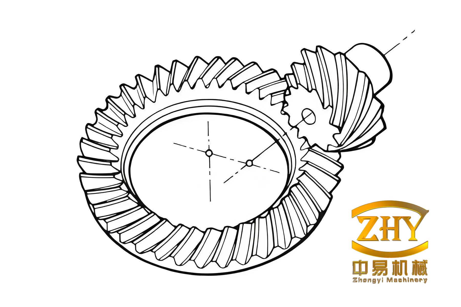
The offset configuration of hypoid gears significantly impacts the vehicle’s center of gravity. By adjusting the offset distance, the car body can be lowered or elevated, thereby improving the stability and off-road performance of the vehicle. The spiral angle of the hypoid driving gear is larger than that of the driven gear, which increases the overlap coefficient between the two wheels, enhances the uniformity of motion, makes the transmission more stable, and reduces noise. The end face modulus of the two meshing hypoid gears is not identical; the modulus of the large gear is smaller than that of the small gear, while the normal modulus is the same. Compared with the spiral bevel gear pinion, the hypoid gear pinion has a larger shaft diameter, which increases the stiffness, strength and load-carrying capacity of the gear teeth. The design and calculation of hypoid gears are far more complex than other gear types because of the offset distance between the two gear axes. The two normal tooth flank profiles of the driving gear have different curvatures and different pressure angles, which also makes the study more difficult than conventional bevel gears. The meshing between the large and small hypoid gears involves both sliding and rolling, which greatly increases the pressure between the gear surfaces and reduces the wear resistance and load-carrying capacity of the tooth surfaces.
The precision plastic forming process of hypoid gears is still in the research stage due to the serious asymmetry of the driving gear tooth shape and the complex tooth profile. Traditional forming processes for bevel gears often generate defects such as incomplete filling, folding, and excessive forming loads. The application of numerical simulation in the precision forging of hypoid gears can effectively solve these problems by providing detailed information about the deformation process. In this work, the Deform-3D software was used for the finite element simulation of the forging process, which allows the analysis of material flow, stress and strain fields, and temperature distributions during the deformation of hypoid gears.
Simulation Theory and Foundation
The rigid-viscoplastic finite element method was adopted to simulate the hot forging process of hypoid gears. This method ignores the elastic deformation of the material and is suitable for analyzing volume forming problems. The material behavior is described by the Levy-Mises constitutive equation, which establishes the relationship between the stress deviator and the strain rate tensor:
$$ \sigma’_{ij} = \frac{2\bar{\sigma}}{3\dot{\bar{\varepsilon}}} \dot{\varepsilon}_{ij} $$
where σ′ij is the deviatoric stress tensor, σ̄ is the equivalent stress, ε̇ij is the strain rate tensor, and ε̇̄ is the equivalent strain rate. The yield criterion adopted in this work is the Mises yield criterion:
$$ \frac{1}{2} \sigma’_{ij} \sigma’_{ij} = k^2 $$
where k is the shear yield stress. For the compressibility condition, the volume constancy constraint is enforced:
$$ \dot{\varepsilon}_v = \delta_{ij} \dot{\varepsilon}_{ij} = 0 $$
where ε̇v is the volumetric strain rate. The Markoov variational principle is used to obtain the exact solution of the boundary value problem. The functional for the rigid-viscoplastic material can be written as:
$$ \Pi = \int_V E(\dot{\varepsilon}_{ij}) \, dV – \int_{S_p} F_i u_i \, dS $$
where E(ε̇ij) represents the plastic deformation work rate function, Fi is the traction on the surface, and ui is the velocity field. The penalty function method was used in this analysis to handle the volume constancy condition. The modified functional is expressed as:
$$ \Pi_P = \int_V \bar{\sigma} \dot{\bar{\varepsilon}} \, dV + \frac{\alpha}{2} \int_V (\dot{\varepsilon}_v)^2 \, dV – \int_{S_p} p_i u_i \, dS $$
where α is a large positive penalty constant. The thermal-mechanical coupled analysis was performed to accurately simulate the hot forging process of hypoid gears. The heat balance differential equation can be expressed as:
$$ \rho c \frac{\partial T}{\partial t} = \lambda \left( \frac{\partial^2 T}{\partial x^2} + \frac{\partial^2 T}{\partial y^2} + \frac{\partial^2 T}{\partial z^2} \right) + \dot{q} $$
where ρ is the material density, c is the specific heat capacity, T is the temperature, λ is the thermal conductivity, t is the time, and q̇ is the heat generation rate due to plastic deformation and friction. The thermal-mechanical coupling is implemented by considering the temperature-dependent flow stress and the heat generated by plastic deformation.
Process Parameters Selection
The material chosen for the hypoid driving gear is 20CrMnTi, which is a low-carbon alloy steel commonly used for carburized gears. This material provides high wear resistance, good bending fatigue strength and excellent contact fatigue strength after carburizing and heat treatment. The mechanical properties of 20CrMnTi at room temperature are summarized in the table below:
| Property | Value | Unit |
|---|---|---|
| Tensile strength, σb | 1080 | MPa |
| Yield strength, σs | 835 | MPa |
| Elongation, δ5 | 10 | % |
| Reduction of area, ψ | 45 | % |
| Impact energy, Akv | 55 | J |
| Hardness | 217 | HB |
The room temperature elongation of 20CrMnTi is only 10%, which means that the material has poor plasticity at room temperature. Therefore, hot precision forging is adopted to form the gear teeth. The forging temperature range for 20CrMnTi is usually 800–1200°C. Based on the complexity of the hypoid gear tooth shape, the extreme deformation amounts of a cold forging process would be difficult to perform. The hot forging process with the temperature range of 1000–1200°C is chosen. At these elevated temperatures, the material exhibits improved plasticity due to the occurrence of dynamic recrystallization.
Laboratory compression tests were performed on a Gleeble-1500 thermal-mechanical simulator to obtain the stress-strain curves of 20CrMnTi at various temperatures and strain rates. The curves are displayed in the following table:
| Strain Rate | Temperature range | Peak flow stress (approximate) |
|---|---|---|
| ε̇ = 10⁻² s⁻¹ | 900–1200°C | 60–150 MPa |
| ε̇ = 10⁻¹ s⁻¹ | 900–1200°C | 80–190 MPa |
| ε̇ = 10⁰ s⁻¹ | 900–1200°C | 110–240 MPa |
| ε̇ = 5 s⁻¹ | 900–1200°C | 150–300 MPa |
These stress-strain curves were input into the material database of the finite element software as the material model of the workpiece. The die material selected for hot forging is 4Cr5MoSiV1, which is equivalent to the American standard AISI-H13 hot work tool steel. The die has a permissible stress of 1500 MPa. The die preheating temperature is set to 350°C, which prevents the billet from cooling down too quickly, thus keeping the deformation resistance low, and also reduces the temperature difference between the interior and the surface of the die, thereby improving the thermal fatigue resistance of the die. Water-based graphite is used as the lubricant, which can achieve a friction coefficient in the range of 0.05–0.19 under hot forging conditions.
In the finite element analysis of plastic deformation, the shear friction condition is commonly used. The friction shear stress is proportional to the shear yield strength of the material being deformed:
$$ \tau_f = m k = \mu’ k $$
where m (0 ≤ m ≤ 1) is the friction factor, k is the shear yield stress, and μ′ = m/√3 is the modified friction coefficient. When m = 1, the friction shear stress reaches its maximum value, which is equal to the shear yield strength of the material. This condition is called the maximum friction condition and is often used in hot plastic forming problems. Since the value of the friction coefficient is influenced by the type of metal, deformation temperature, deformation speed and other factors, the friction coefficient selection in the simulation follows the common practice that a value in the range of 0.1–0.3 is reasonable in hot forging with lubrication.
The closed-die forging method, which is also known as the enclosed die forging or闭塞锻造, was selected in this work. The principle of closed-die forging is that the upper and lower dies are first closed together, and then one or two punches move to exert pressure on the billet material, causing the material to flow into the tooth cavities. Since the tooth shape of the hypoid driving gear is complex and the material flow is difficult during the forging process, the combination of upsetting and extrusion is used in the closed-die forging process. For the selection of forging equipment, the friction screw press is chosen due to its advantages of no fixed lower dead center, strong process adaptability, and high forging accuracy. The forming force can be calculated using:
$$ F_P = \alpha \sigma_b F \left(1 + 0.1 \sqrt{\frac{V}{F}}\right) $$
where α is the coefficient related to the die type (taking a value of 5 for closed-die forging), F is the projected area of the forging including the flash, V is the volume of the forging, and σb is the flow stress of the metal at the final forging stage. The calculation shows that the forging force required for the hypoid driving gear at 1100°C is about 454 tons, and at 1000°C is about 826 tons. Considering additional calculations and the specific deformation characteristics of the hypoid gears, the required forming force was initially determined to be above 800 tons.
Forging Drawing and Blank Design
The precision forging drawing was designed based on the part drawing of the hypoid driving gear as well as the principles of cold forging drawing design. The part is a small gear with 6 teeth, a module of 12.032 mm, a spiral angle of 45.998°, a left-hand spiral direction, and an offset distance of 44.45 mm. The basic geometric parameters of the hypoid driving gear are listed in the table below:
| Parameter | Value | Unit |
|---|---|---|
| Number of teeth | 6 | – |
| Module | 12.032 | mm |
| Spiral angle | 45.998 | degree |
| Spiral direction | Left-hand | – |
| Obtuse offset | 44.45 | mm |
| Cutter diameter | 304.8 | mm |
| Mean pressure angle | 22.5 | degree |
| Outer end addendum | 15.413 | mm |
| Outer end whole depth | 19.816 | mm |
Several key aspects should be considered when designing the forging drawing of hypoid gears. The parting surface of the forging is selected at the large end of the tooth, which is where the largest horizontal projected dimension is located. The machining allowance for the tooth profile is determined as 0.75–1.2 mm per side. Since the friction screw press is equipped with an ejection device and the tooth shape of the hypoid driving gear has a natural taper from the small end to the large end, no additional forging draft angle is needed. The fillet radius is designed according to the following relations:
$$ r = \text{machining allowance} + a $$
$$ R = (2 \sim 3) r $$
where a is the corner radius or chamfer at the corresponding position of the part, r is the external fillet radius, and R is the internal fillet radius. The shrinkage of the hot forging is considered when calculating the hot forging dimensions:
$$ L = l (1 + \delta) $$
where L is the hot forging dimension, l is the cold forging dimension, and δ is the shrinkage rate of steel at the final forging temperature, which is taken as 1.5%. The designed precision forging drawing forms the basis for the design of the blank shape and geometry.
Based on the forging drawing and the principle of closed-die forging, the blank shape design is essential for the success of the precision forging of hypoid gears. The purpose of the blank design is to ensure proper positioning of the billet in the die cavity, easy filling of the tooth cavity, and short material flow path. The design principle is that the blank shape must be contained within the geometric body formed by the root cone and the two cylindrical surfaces with the large-end and small-end root circle diameters as the outer contours. According to the direction of the punch force, seven different blank shapes and five corresponding forming schemes were designed in this work. The five forming schemes are summarized in the table below:
| Scheme No. | Forming method | Blank shape description |
|---|---|---|
| 1 | Single-action punch, force from the small end | Cylinder with small-end root diameter |
| 2 | Single-action punch, force from the large end | Large-end cylindrical blank |
| 3 | Single-action punch, force from the large end | Conical blank with matching taper |
| 4 | Single-action punch, force from the large end | Shank-like blank with smaller large-end diameter |
| 5 | Double-action punch, force from both ends | Cylindrical blank with stepped diameters |
For scheme 1, a single-action punch is applied from the small end of the billet. The small end of the tooth is formed first, and the large end is formed afterward. The material flow path is short and continuous during the forming process, which is beneficial for avoiding internal defects such as folds. For schemes 2 and 3, the punch force is applied from the large end. In these cases, the material flow is similar to upsetting, with the middle of the billet expanding first, then the large end and the small end forming sequentially. However, because the maximum blank diameter is much larger than the small-end root circle diameter, incomplete filling at both ends of the tooth is likely to occur. For scheme 4, although the final forming effect can be better, the diameter difference between the large end of the billet and the root circle of the large-end tooth causes a step change in diameter, which can lead to folding defects during the forming process. Scheme 5 uses a double-action punch with forces applied from both ends, but similar folding problems can also occur as in scheme 4 due to the improper flow path.
Finite Element Modeling
To reduce the computational cost of the finite element simulation, only the tooth body of the hypoid driving gear was considered as the simulation object in the comparative analysis of different forming schemes. The complete finite element model was established using UG software for three-dimensional geometry modeling, and the models were imported into Deform-3D for numerical simulation. A three-dimensional model of the hypoid gear tooth body is displayed in the table. Four-node tetrahedral elements were used to mesh both the billet and the dies. The billet was meshed with 80,000 tetrahedral elements, and the dies were also meshed with 80,000 elements for heat transfer analysis.
The environment temperature was set to 20°C, the billet temperature to 1100°C, the die preheating temperature to 350°C, the heat transfer coefficient between the billet and the environment to 0.02, the heat transfer coefficient between the billet and the dies to 11, and the fraction of plastic deformation work converted into heat to 0.9. The friction coefficient in the simulation was set to 0.3, and the shear friction model was used. For the punching speed, based on the performance of the friction screw press, the punch velocity of schemes 1–4 was set to 200 mm/s. In scheme 5, where two opposing punches are used, the displacement of the large-end punch is 40 mm and that of the small-end punch is 45 mm; therefore, the large-end punch velocity was set to 200 mm/s and the small-end punch velocity to 225 mm/s. During the simulation, a volume compensation option was selected for loss of element volume during remeshing to ensure accuracy of the numerical results.
The strain rate during the forming process can be estimated by:
$$ \dot{\varepsilon} = \frac{1}{L_0} \frac{dL}{dt} $$
For scheme 1, the original length of the deforming body is 221 mm, and the length change after deformation is 131 mm. If the entire forging process lasts for about 2 seconds, the average strain rate is approximately 0.296 s⁻¹, which falls within the range of the stress-strain curves measured in the laboratory compression test. This verifies that the punch velocity setting is reasonable.
Simulation Results and Scheme Optimization
The simulation results of various forming schemes were compared in terms of tooth shape filling, equiva-lent stress distribution, equivalent strain distribution and forming load. Special attention was paid to the filling condition of the tooth cavity corners, which are the most difficult regions to fill in the precision forging of hypoid gears.
Tooth Filling Analysis
For scheme 1, the tooth filling process shows that the small-end tooth is formed first, followed by the large-end tooth. The material flow is smooth and continuous, with no signs of interweaving or disorder inside the billet. The tooth working part is fully filled with a clear outline. However, the corner at the large end of the tooth (the intersection of the face cone and the back cone) exhibits an incomplete filling defect. This defect can be avoided by designing an appropriate fillet radius at the large-end corner of the tooth in the forging drawing, which can smoothly guide the material flow.
For schemes 2 and 3, the tooth filling process shows that during the initial stage, the billet undergoes a deformation similar to upsetting, with the axial dimension decreasing and the radial dimension increasing. Due to friction at the contact surfaces and the influence of the conical shape of the billet, the tooth apex at the middle portion slightly close to the large end first contacts the die cavity and begins to form. The material deformation is non-uniform, making it easy to generate additional stress and defects. Since the maximum blank diameter is too large relative to the small-end root circle diameter, both ends of the tooth show incomplete filling defects at the final stage, with the large-end “collapsed corner” being more serious than the small end.
For scheme 4 and scheme 5, the tooth filling can be completed successfully at the corners, but since the billet large-end diameter is smaller than the root circle diameter of the large-end tooth, a step change in diameter with a right-angle transition is formed. In the forming process, as metal continuously flows from the large end into the die cavity, a phenomenon similar to backward extrusion occurs at the step junction line, producing a reciprocating flow path of the metal and resulting in severe folding defects inside the large-end tooth. Even if a sufficiently large fillet is applied at the corner, the folding defect cannot be completely eliminated because of the diameter difference between the blank and the die cavity.
Therefore, the filling analysis reveals that from the perspective of material flow and tooth shape formation, scheme 1 is the preferred option for the precision forging of hypoid gears. Scheme 1 enables smooth metal flow from the small end toward the large end, with gradual and continuous filling that avoids folding and other internal defects.
Stress and Strain Analysis
The equivalent stress distribution reflects the resistance to deformation and stress concentration at various locations of the billet. Simulation results of the final forming stage for different schemes show that the locations of the maximum equivalent stress are all at the large end or the large-end corner of the tooth, indicating that the large-end of the tooth is the most difficult region to fill. The maximum equivalent stress values reached during final forming for the different schemes are summarized in the table below:
| Scheme | Maximum equivalent stress (MPa) | Maximum equivalent strain |
|---|---|---|
| 1 | 377 | 8.54 |
| 2 | 4880 | 4.62 |
| 3 | 4300 | 3.49 |
| 4 | 2140 | 8.53 |
| 5 | 1140 | 4.95 |
Scheme 1 presents the smallest maximum equivalent stress of 377 MPa, significantly lower than the other schemes. This is because in scheme 1, the material mainly flows axially under the punch pressure from the small end, and the radial flow of the central material fills the tooth cavity through a squeezing effect. The deformation is carried out under a triaxial compressive stress state, giving the material a good plasticity and low deformation resistance. The material flow path is short and smooth, and the deformation is uniform, resulting in a relatively small stress value.
The equivalent strain distribution reflects the severity and accumulation of deformation in the billet. The position of the maximum equivalent strain varies across different schemes. In scheme 1, the maximum equivalent strain appears at the small end of the tooth, whereas in schemes 2, 3, and 4, it appears at the large end of the tooth. In scheme 5, the maximum equivalent strain appears at both ends of the tooth. This is because the direction of the punch force determines the sequence of deformation, and the parts that participate in the deformation first have correspondingly larger cumulative strain values. Scheme 1 has a maximum equivalent strain of 8.54, which is larger than the values obtained in schemes 2, 3, and 5, and slightly larger than that of scheme 4. The larger equivalent strain indicates that the material has experienced larger cumulative deformation, indicating more sufficient deformation and better filling of the tooth cavity.
Forming Load Analysis
The forming load is one of the key factors for selecting the forming scheme, since a high forming load can easily overload the die, affect the service life of the die, and require greater energy from the equipment. The load-stroke curves of the punches for different schemes show that all five schemes exhibit a similar change pattern: the load increases gradually with increasing stroke in three stages. In the tooth filling stage, the load curve rises steadily, indicating that the forming load gradually increases and the deformation resistance increases. The curvature of the curve increases gradually, meaning the forming load increases faster as the forming becomes more difficult. Comparing the different schemes, the curve of scheme 1 has a noticeably smaller curvature with the slowest growth rate, indicating relatively smooth metal flow and easier filling process compared to the other schemes. The maximum forming loads reached by all schemes are summarized below:
| Scheme | Maximum forming load (tons) |
|---|---|
| 1 | 198 |
| 2 | 241 |
| 3 | 239 |
| 4 | 265 |
| 5 | 252 |
From the table, scheme 1 has the smallest maximum forming load of 198 tons, which is lower than all other schemes. This implies that scheme 1 requires a smaller equipment tonnage, contributes to extending the die life, and consumes less energy. Therefore, from the perspectives of tooth filling, stress-strain distribution, and forming load, scheme 1 was determined to be the optimal forming scheme for the precision forging of hypoid gears.
Influence of Process Parameters
The selection of process parameters directly affects the deformation process, and inappropriate process parameters will lead to defects such as folding, incomplete filling, and insufficient dimensional accuracy. In this work, the two most important process parameters, friction coefficient and forging temperature, were studied through multiple numerical simulations. The influence laws of these parameters on the forming quality of hypoid gears were analyzed. Three sets of simulation experiments were designed as follows: the first group uses a friction coefficient of 0.1, 0.2, and 0.3 at a constant forging temperature of 1050°C; the second group uses forging temperatures of 1000°C, 1050°C, and 1100°C at a constant friction coefficient of 0.3.
Effect of Friction Coefficient
The simulation results at a constant forging temperature of 1050°C with different friction coefficient values show that the maximum equivalent stress increases with increasing friction coefficient. When the friction coefficient is 0.1, the maximum equivalent stress is 366 MPa; when it is 0.2, the stress is 428 MPa; and when it is 0.3, the stress is 441 MPa. The increase in stress is attributed to the increased frictional resistance at the billet-die interface, which hinders the metal flow and increases the deformation resistance. When the friction coefficient is small, the equivalent stress is small and evenly distributed, indicating that the plastic deformation of the billet is relatively uniform and the metal flows smoothly.
As the friction coefficient increases, the forming load also increases correspondingly, as shown in the load-stroke curves. A larger friction coefficient increases the difficulty of material filling, which is detrimental to the forming quality. Therefore, selecting a reasonable lubrication method and lubricant to minimize the friction coefficient can reduce the forming load, lower the equipment requirements, reduce energy consumption, reduce die wear, and extend die service life. The friction coefficient should be considered as an important influencing parameter in the study of the precision forging of hypoid gears.
Effect of Forging Temperature
The simulation results at a constant friction coefficient of 0.3 with different forging temperatures show that as the forging temperature increases, the maximum equivalent stress decreases. When the forging temperature is 1100°C, the maximum equivalent stress is 377 MPa; at 1050°C, the stress is 441 MPa; and at 1000°C, the stress is 446 MPa. This is because during hot forging, the metal undergoes dynamic recovery and recrystallization, which eliminates the effect of work hardening. With increasing temperature, the softening effect of recovery and recrystallization is enhanced, and the increased atomic kinetic energy improves the mobility of dislocations, increases the number of slip systems, and improves the coordination of deformation between grains. Grain boundary sliding and diffusion creep are also enhanced with temperature increase. As a result, the deformation resistance decreases, so the equivalent stress decreases with increasing temperature.
The forming load also decreases with increasing forging temperature. A lower forging temperature requires a larger forming load and makes the material flow more difficult, which has an adverse effect on the filling of the tooth cavity. Therefore, within the allowable forging temperature range of hypoid gears, a higher forging temperature should be chosen whenever possible, as the higher temperature improves the fluidity of the material, reduces the forming load, and ensures the forming quality of the gear product, while also reducing energy consumption and extending die life.
Detailed Numerical Simulation of the Optimized Scheme
A detailed numerical simulation study of the optimized scheme was conducted to reveal the forming laws of the precision forging process of the hypoid driving gear. The complete finite element model established in this study consists of the billet, the upper die, the lower die, and the punch. The simulation results are analyzed in terms of the mesh evolution, stress field, strain field, velocity field, temperature field, and load-stroke characteristics.
Mesh Evolution
In the initial state, the internal mesh of the billet is uniform. After the punch contacts the billet and begins to move downward, the metal begins to enter the tooth cavity from the small end, and the surface mesh density of the billet gradually becomes denser from the small end toward the interior. As the deformation continues, the metal gradually fills from the small end toward the large end. At the end of the deformation, the mesh density of the tooth-filling part is much greater than that of the internal part of the billet. The variation of the mesh density indicates that the entire forming process is a gradual transition from the small end to the large end, and the metal can fill the entire tooth cavity with complete tooth profiles.
Equivalent Stress Field
The analysis of the equivalent stress field shows that its value increases gradually at all positions of the billet as the forming process proceeds, which is a result of work hardening. Since the process is a hot forging process, the stress distribution is uniform and transitions are smooth, and the material has good fluidity. In the initial deformation stage, the stress action zone is first generated in the arc-shaped region near the small end of the tooth, and the stress value in this zone gradually decreases from the outside to the inside. This is because the metal first contacts the die cavity at the small end, and the deformation resistance is generated under the constraint of the die. During the filling of the small-end tooth, the stress values at the tooth root are greater than those at the tooth tip because the tooth root is the first region to contact the die cavity. After the small-end tooth is completely filled, as the metal continues to fill toward the large-end, the small-end tooth root continues to flow along the root toward the large-end, while the small-end tooth tip also flows along the tip toward the large-end but at a slower speed, resulting in a smaller stress for the metal being re-extruded into the small-end root than the stress of the originally formed tooth tip region. At this stage, the minimum stress is located at the center of the billet. When the large-end tooth is completely filled, the maximum stress appears at the corner of the tooth, reaching a value of 279 MPa at the final stage. The shank portion of the billet is constrained by the die and does not participate in the deformation, so the stress in this portion is low.
Equivalent Strain Field
The equivalent strain also increases gradually throughout the deformation due to the accumulation of deformation. The deformation begins at the small-end and gradually propagates to the large-end. The equivalent strain value is largest at the tooth root of the small end, indicating that the material flow is most intense in this region and the cumulative deformation is greatest. The equivalent strain value decreases from the small end to the large end, and along the radial direction, it decreases from the tooth root to the tooth tip. This is because the metal fills the small end first, and the deformation amount of the small-end is larger than that of the large-end. The maximum equivalent strain value reaches 4.58 at the small-end tooth root. The shank part of the billet does not participate in the deformation, so its equivalent strain is nearly zero.
Velocity Field Analysis
The velocity field directly reflects the material flow pattern during the deformation process. After the deformation begins, the cylindrical part of the billet flows axially in the vertical direction at a high speed, while the tooth-shaped part of the billet flows radially and downward in a radiating pattern from the small-end toward the large-end. Since the metal fills the small end first and the large end last, the deformation velocity gradually decreases from the small end to the large end. The metal flow direction is clear, and the difference between the maximum and minimum velocities is small. Due to the influence of the spiral tooth shape, the metal flow has both radial and tangential components. Since the two normal tooth flank profiles of the driving gear have different curvatures and different pressure angles, the tooth shape is asymmetric, and the tangential movement is more intense during the filling of the tooth tip. At the final forming stage of the large-end head, incomplete filling is likely to occur at the intersection of the face cone and the back cone of the large-end head, so a fillet must be designed at this position in the forging drawing to avoid this defect. Overall, the velocity distribution is reasonable and uniform, and no flow reversal or interweaving phenomena occur, indicating good filling conditions without internal folding defects.
Temperature Field Analysis
The temperature field distribution during the deformation process shows that the temperature of the outer part of the billet gradually decreases and extends inward. This is because the outer part is in contact with the die and heat conduction is more rapid there than in the interior. In the initial deformation stage, the surface temperature of the cylindrical part decreases due to heat conduction with the die wall, but the temperature of the tooth-shaped part maintains above 1000°C because there is a gap between it and the die. In the filling stage, the temperature at the small-end tooth root remains high because the deformation work and friction work compensate for the heat loss. After the small end is filled, the small-end tooth tip comes in contact with the die and loses heat without compensation, so its temperature decreases to around 900–950°C. The large-end tooth tip is the last to come in contact with the die, so its temperature remains very high at about 1050–1100°C during the filling of the large end. Overall, the temperature difference of the billet is within 200°C, which is a relatively uniform distribution. Most regions maintain temperatures between 900°C and 1000°C, which is favorable for avoiding large residual thermal stress in both the forging and the die.
Load-Stroke Curve Analysis
The load-stroke curve of the punch in the optimized scheme can be divided into three stages: the initial stage, the filling stage, and the final stage. In the first stage, from the initial state to the moment the billet surface comes into contact with the small-end die cavity, the deformation is equivalent to an upsetting process and the load curve rises linearly. In the second stage, from when the billet contacts the small-end cavity to when the billet completely contacts the large-end cavity, the filling process occurs, and the tooth is gradually filled from the small-end to the large-end. This is the longest stage, and the load curve rises steadily with an increasing slope, indicating increasing deformation resistance. In the final stage, from when the billet completely contacts the large-end cavity to the completion of the entire tooth filling, the tooth shape is mostly filled, and this stage is mainly for completing the filling of the local corner areas. Although the displacement is small, the remaining free surface area is very limited, so the load curve rises steeply and rapidly, reaching a maximum value of 153 tons (1530 kN) at the terminal stage. A sudden drop and then a sudden rise appear in the final part of the curve due to severe mesh distortion and remeshing during the simulation.
Equipment Selection and Experimental Analysis
The closed-die forging process used in this study requires both the die clamping force and the punch force to be taken into account when selecting the forging equipment. In the closed-die forging concept, the total forging load equals the sum of the die clamping force and the punch squeezing force. In the finite element model of scheme 1, the lower die not only bears the clamping force between the upper and lower dies but also the squeezing force of the punch. Therefore, the load value simulated on the lower die should be used to select the appropriate equipment tonnage. The load-stroke curve of the lower die in the simulation shows a maximum load of approximately 702 tons. To ensure the precision of the forging and to allow the dies to close fully, an equipment with a slightly larger tonnage is necessary; therefore, a friction screw press with a nominal capacity of 800 tons is recommended. This result is consistent with the theoretical calculations using the empirical formulas for forging force, which verifies the reliability of the numerical simulation results.
In the previous trial experiments conducted at the partner company, the closed-die forging of the hypoid driving gear encountered several problems, including damaged bearings and the inability to eject the forging from the die. Due to the relocation of the production facility, further experiments could not be completed during this research period. However, the numerical simulation results from this work provide important guidance for the design of the new die structure and the selection of forging equipment, which will be valuable for the future practical implementation of the precision forging process for hypoid gears.
Conclusions
In this research, the precision forging process of a hypoid driving gear was systematically investigated through the combination of analytical calculation and three-dimensional finite element numerical simulation. The main conclusions are summarized as follows:
1. The design principle of the blank shape for the precision forging of hypoid driving gears was established. For the effective filling of the tooth cavity, the material must be compressed from both ends of the tooth body, forcing the central metal to flow radially to fill the tooth cavities and form the spiral tooth shape. The blank shape must be contained within the geometric body formed by the root cone and the two cylindrical surfaces with the large-end and small-end root circle diameters as the outer contours.
2. Based on the comparative analysis of five different forming schemes, the optimal scheme for the precision forging of the hypoid driving gear was determined. The optimal scheme uses a single-action punch applying force from the small end of the billet. The billet ends have diameters slightly smaller than the root circle diameters of the two ends of the tooth body. This scheme enables smooth metal flow from the small end toward the large end with gradual and continuous filling, small forming load, and no internal defects such as folds.
3. The influence laws of the major process parameters on the forming of hypoid gears were obtained. For a given forging temperature, an increase in the friction coefficient increases the forming load and the equivalent stress, which is detrimental to the filling of the tooth cavity. For a given friction coefficient, an increase in the forging temperature reduces the forming load and the equivalent stress, which benefits the material flow and the tooth filling.
4. The deformation characteristics and forming laws of hypoid gears during precision forging were revealed through detailed numerical simulation. The metal first fills the small-end tooth and then the large-end tooth. During the filling of the tooth cavity, the metal flow has both radial and tangential components due to the spiral tooth shape. The tangential movement is more intense at the tooth tip, and a fillet must be designed at the intersection of the face cone and the back cone of the large-end head to avoid incomplete filling. The whole forming process can be divided into three stages: an initial upsetting stage, a filling stage with steadily increasing load, and a final stage with a sharply rising load for completing the filling of local corners.
5. The simulation results suggest that an 800-ton friction screw press is appropriate for the precision forging of the hypoid driving gear. This finding is consistent with the theoretical calculation of the forging force, and it provides useful reference for the selection of forging equipment and the design of realistic production processes for hypoid gears.