
1. Introduction
Spur gears are among the most widely used mechanical transmission components in various industrial sectors, including automotive, marine, aerospace, and agricultural machinery. Their primary function is to transmit motion and power between parallel shafts. In the context of modern manufacturing, the demand for high-performance and cost-effective spur gears has been continuously increasing. Traditional manufacturing routes for spur gears rely heavily on machining processes such as hobbing, shaping, and broaching. Although these processes can achieverelative high dimensional accuracy, they suffer from significant drawbacks, including low material utilization, long production cycles, and interrupted metal flow lines, which degrade the mechanical properties of gear teeth. In contrast, precision forging of spur gears offers enhanced material integrity, improved fatigue strength, and higher production efficiency. However, precision forging of spur gears is not without challenges. Key issues include high forming loads, insufficient filling at tooth tips and root corners, low dimensional accuracy, and premature die failure. To address these challenges, a compound forming approach combining warm and cold forging has been developed. This study focuses on the key technologies of precision forging compound forming of spur gears, taking a steering gear from agricultural machinery as a case study. The objective is to propose a new process route, optimize process parameters, establish a mathematical model for forming force, and validate the approach through numerical simulation.
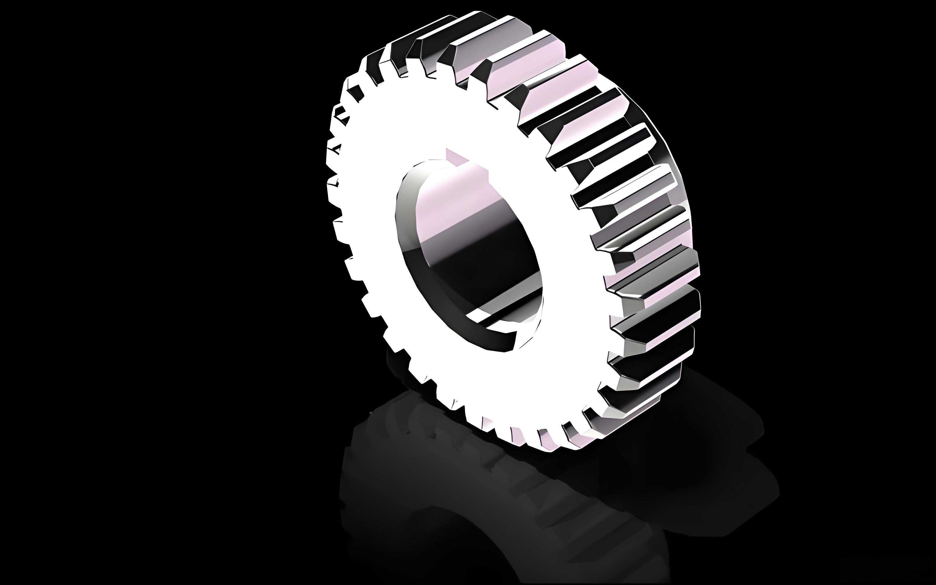
The steering gear investigated in this work consists of a large-module spur gear portion and an involute spline portion. The spur gear has a module of 4 mm, 16 teeth, a pressure angle of 20°, and a profile shift coefficient of 0.4. The spline has a module of 2.5 mm, 22 teeth, a pressure angle of 0°, and a profile shift coefficient of 0.765. The original manufacturing route was purely machining, with a material utilization of only about 35%. To improve material utilization and mechanical performance, a warm–cold compound forming process was proposed. The main contributions of this paper are as follows:
- Proposal and validation of a new process route for the spur gear, including warm preforming and cold coining.
- Numerical simulation of the spur gear and spline forming processes using DEFORM-3D.
- Multi-objective optimization of process parameters using response surface methodology to reduce residual stress and forming load.
- Development of a mathematical model for the forming force of spur gears using the slab method, including the effect of a mandrel gap.
- Verification of the optimized process through production-oriented numerical simulation.
2. Process Analysis and Die Design
2.1 Overview of Forming Processes for Spur Gears
Hot forging, warm forging, and cold forging are the three main categories for forging spur gears. Hot forging offers good formability and low forming load but suffers from oxidation and low dimensional accuracy. Cold forging provides excellent dimensional accuracy and surface quality but requires high forming loads and robust dies. Warm forging, typically performed between 650°C and 900°C, bridges the gap between hot and cold forging. It offers moderate forming loads, limited oxidation, and acceptable accuracy. However, for complex geometries such as the steering gear considered here, a single warm forging operation may not achieve the required tooth accuracy. Hence, a combination of warm forging followed by cold coining (warm–cold compound forming) is adopted. This approach leverages the advantages of both processes: warm forging facilitates material flow and complex shape formation, while cold coining improves surface finish and dimensional accuracy.
2.2 Workpiece Material and Forging Difficulty
The gear material is 20CrMnTi alloy steel, which is widely used in the automotive and agricultural machinery industries. This steel has high hardenability and excellent fatigue strength. However, its high deformation resistance at room temperature makes cold forging particularly challenging. To reduce the forming load and improve die life, the workpiece is initially softened by annealing. During the warm forging process, the material is heated to a temperature range of 800–850°C, where its flow stress is significantly lower than at room temperature.
Several features make the steering gear difficult to forge:
- Presence of a central through-hole requiring a mandrel.
- Stepped shaft section requiring local deformation.
- Two grooves adjacent to the stepped shaft, which are difficult to fill.
- External dog teeth (clutch teeth) on the spur gear portion, which may present filling difficulties.
Since the gear is essentially axisymmetric, forward and backward extrusion are both applicable. The process route was designed to first form a hollow preform, then preform the clutch teeth, followed by warm coining of the spur gear teeth and the spline, and finally cold coining to achieve the required accuracy.
2.3 Process Route
The overall process route is as follows:
- Precision cutting of the billet.
- Medium-frequency induction heating.
- Warm preforming of the central hole.
- Punching out the web (removal of the internal flash).
- Warm extrusion of the spur gear teeth and stepped shaft.
- Warm extrusion of the spline.
- Annealing.
- Cold coining of the spur gear teeth.
- Final machining and heat treatment.
A schematic illustration of the process route is shown in Table 2.1.
| Stage | Operation | Purpose |
|---|---|---|
| 1 | Precision cutting | Obtain a cylindrical billet with accurate volume |
| 2 | Induction heating | Heat billet to warm forming temperature |
| 3 | Warm preforming | Create a central hole and approximate outer contour |
| 4 | Punching web | Remove the central flash and obtain a hollow preform |
| 5 | Spur gear warm extrusion | Form the large-module spur gear teeth and stepped shaft |
| 6 | Spline warm extrusion | Form the involute spline |
| 7 | Annealing | Relieve residual stress and soften for cold coining |
| 8 | Cold coining | Improve tooth accuracy and surface finish |
| 9 | Machining | Remove excess material and achieve final dimensions |
2.4 Die Structure Design
The die structure is a critical factor affecting the quality of forged spur gears. The thermal expansion of the billet and the die must be considered when designing the die cavity dimensions. The thermal expansion of the billet can be estimated by
$$\Delta L_b = L_0 \beta_b (T_f – T_0)$$
where \(L_0\) is the reference dimension, \(\beta_b\) is the linear expansion coefficient of the billet material, \(T_f\) is the final forging temperature, and \(T_0\) is the initial temperature. For 20CrMnTi at about 800°C, the expansion was calculated to be 0.81 mm. Similarly, the die expansion was calculated to be 0.47 mm for the spur gear die and 0.33 mm for the spline die. Therefore, the die cavity dimensions were designed accordingly to guarantee proper filling and easy ejection.
The punch and die materials were selected based on strength and wear resistance. The punch was made of T10A steel, hardened to 55–58 HRC. The die was made of Cr12MoV steel. Both were designed as integral structures because the calculated internal pressures were within allowable limits. The assembly drawings of the preforming and final forging dies were obtained, and the motion process was analyzed. In the forming stage, the upper punch moves down, and the rubber pad presses the upper die against the lower die to form a closed cavity. In the return stage, the punch retracts and the ejector pins push the forging out.
3. Finite Element Numerical Simulation
3.1 Modeling Assumptions and Governing Equations
To model the plastic deformation of spur gears, a rigid-viscoplastic material model was adopted. The basic assumptions include: negligible elastic deformation, incompressibility, isotropy, and the absence of body forces. The governing equations for rigid-plastic deformation are:
Equilibrium equation:
$$\sigma_{ij,j} = 0$$
Strain-rate compatibility:
$$\dot{\varepsilon}_{ij} = \frac{1}{2} (v_{i,j} + v_{j,i})$$
Levy–Mises constitutive relation:
$$\dot{\varepsilon}_{ij} = \dot{\lambda} \sigma’_{ij}$$
Mises yield criterion:
$$\bar{\sigma} = \sqrt{\frac{3}{2} \sigma’_{ij}\sigma’_{ij}}$$
The finite element formulation follows the Markov variational principle:
$$\pi = \int_V \bar{\sigma} \dot{\bar{\varepsilon}} \, dV – \int_{S_F} F_i v_i \, dS$$
To enforce the incompressibility condition, a penalty function is used. The penalty method adds a large positive term to the variational functional:
$$\pi_p = \int_V \bar{\sigma} \dot{\bar{\varepsilon}} \, dV – \int_{S_F} F_i v_i \, dS + \frac{\alpha}{2} \int_V (\dot{\varepsilon}_v)^2 \, dV$$
where \(\alpha\) is the penalty factor and \(\dot{\varepsilon}_v\) is the volumetric strain rate. The penalty method is preferred because it reduces the number of unknowns and improves computational efficiency.
3.2 Model Setup in DEFORM-3D
The finite element simulations were performed using DEFORM-3D. The gear geometry and the die models were created in SolidWorks and imported into DEFORM-3D. Because of the symmetry of the workpiece, only a quarter of the model was simulated to reduce computational cost. The workpiece material was modeled using the AISI-4120 material data available in the DEFORM library, since its flow stress properties are similar to those of 20CrMnTi. The dies were treated as rigid bodies. Tetrahedral elements were used, with a relative mesh density control. The spur gear forming model consisted of about 50,000 elements, while the spline forming model used about 30,000 elements. A shear friction model was applied, with a friction coefficient of 0.08. The initial billet temperature was set to 800°C, and the die temperature was set to 200°C. The ram speed was 10 mm/s for the initial simulation. More detailed parameters are listed in Table 3.1.
| Parameter | Value |
|---|---|
| Ram speed (mm/s) | 10 |
| Billet material | AISI-4120 |
| Die material | H-13 |
| Young’s modulus (MPa) | 206754 |
| Poisson’s ratio | 0.3 |
| Yield strength (MPa) | ≥835 |
| Number of elements (spur/spline) | 50000/30000 |
| Element type | Tetrahedral |
| Friction type | Shear |
| Friction coefficient | 0.08 |
| Billet initial temperature (°C) | 800 |
| Die temperature (°C) | 200 |
3.3 Simulation Results
3.3.1 Deformation behavior
The mesh evolution during the spur gear forming process is shown in Figure 3.1. Initially the mesh is uniform. As the punch moves downward, the billet is compressed axially and expands radially. The mesh near the tooth tips and roots becomes distorted, indicating heavy localized deformation. The adaptive remeshing capability of DEFORM-3D ensures that the mesh quality is maintained throughout the simulation. During the final stage of filling, the mesh density is higher in the tooth tip regions, which correctly captures the severe deformation required to fill the die corners.
3.3.2 Velocity field
The velocity field during spur gear forming reveals the metal flow pattern. In the early stage, material under the punch flows axially downward and radially outward. Later, the material flows into the tooth cavities, with the highest velocities occurring near the die entrance. In the spline forming process, the material flow is similar but with less resistance due to the smaller module. The metal flow is generally smooth, indicating that the proposed geometry is conducive to filling.
3.3.3 Stress and strain fields
The equivalent stress distribution during spur gear forming shows that high stress concentrations develop near the tooth root and tip regions. At the final forming stage, the stress in the tooth tip region reaches the highest value, which may cause die wear or even fracture. The equivalent strain distribution reveals that the largest plastic deformation occurs at the tooth tips, while the core of the workpiece experiences relatively lower strain. This inhomogeneous strain distribution is typical for gear forging.
3.3.4 Temperature field
The temperature distribution during forming is affected by the deformation heat and the heat exchange with the die. In the spur gear forming simulation, the temperature in the tooth regions increases slightly due to plastic work. The temperature variation is relatively small, and the gradient is confined to the contact zones between the workpiece and the die. This suggests that the selected forming temperature range is acceptable for 20CrMnTi steel.
3.3.5 Forming load
The predicted forming load versus stroke curves for the spur gear and spline forming are shown in Figure 3.2. The curve can be divided into three stages. In the initial stage, the load increases gradually. In the intermediate stage, as the material begins to fill the die cavity, the load rises more rapidly. In the final stage, when the die cavity is nearly full, the load increases sharply due to the constrained material flow. The maximum load for the spur gear forming was about 9000 kN, while that for the spline forming was about 5000 kN. These values are critical for selecting the capacity of the forging press.
4. Multi-Objective Optimization of Process Parameters
4.1 Methodology: Response Surface Method
Response surface methodology (RSM) is a collection of statistical and mathematical techniques used to develop, improve, and optimize processes. In this study, RSM was employed to examine the influence of friction coefficient, ram speed, and billet temperature on residual stress and forming load of spur gears. The central composite design (CCD) was used to design the experiments. The ranges of the three variables were:
- Friction coefficient: 0 – 0.2
- Ram speed: 5 – 20 mm/s
- Billet temperature: 700°C – 850°C
The experiment design consisted of 17 runs, including center points. The response variables were the maximum equivalent residual stress and the required forming load. Finite element simulations were performed for each combination. The design matrix and results are summarized in Table 4.1.
| Run | A: friction | B: ram speed (mm/s) | C: billet temp (°C) | Residual stress (MPa) | Forming load (kN) |
|---|---|---|---|---|---|
| 1 | 0.1 | 12.5 | 775 | 228 | 1090 |
| 2 | 0.2 | 12.5 | 700 | 293 | 1310 |
| 3 | 0.1 | 12.5 | 775 | 220 | 1075 |
| 4 | 0.1 | 20 | 700 | 270 | 1170 |
| 5 | 0 | 20 | 775 | 253 | 948 |
| 6 | 0.1 | 20 | 850 | 273 | 877 |
| 7 | 0.2 | 12.5 | 850 | 172 | 956 |
| 8 | 0.1 | 5 | 850 | 164 | 779 |
| 9 | 0.1 | 5 | 700 | 266 | 1171 |
| 10 | 0 | 12.5 | 700 | 289 | 1162 |
| 11 | 0.1 | 12.5 | 775 | 220 | 1110 |
| 12 | 0 | 12.5 | 850 | 166 | 773 |
| 13 | 0.1 | 12.5 | 775 | 234 | 1079 |
| 14 | 0 | 5 | 775 | 191 | 845 |
| 15 | 0.2 | 5 | 775 | 215 | 981 |
| 16 | 0.2 | 20 | 775 | 219 | 1070 |
| 17 | 0.1 | 12.5 | 775 | 218 | 1088 |
4.2 Response Surface Models
Using Design-Expert software, second-order polynomial response surface models were fitted to the simulation data. The final regression equations for residual stress \(R\) (MPa) and forming load \(F\) (kN) are given below, where \(A\), \(B\), and \(C\) are the coded variables for friction coefficient, ram speed, and billet temperature, respectively:
Residual stress model:
$$R = 224.18 – 0.06A – 19.88B – 37.88C – 4.5AB – 4.5AC + 21.25BC + 8.87A^2 + 3.18B^2 + 29.87C^2$$
Forming load model:
$$F = 1088.40 + 73.63A + 36.13B – 178.50C – 3.50AB – 8.75AC + 24.75BC + 4.75A^2 + 83.89B^2 – 0.11C^2$$
The analysis of variance (ANOVA) was carried out to verify the adequacy of the developed models. Tables 4.2 and 4.3 present the ANOVA results for residual stress and forming load, respectively. The model \(F\)-values are 87.99 and 93.01, both with \(p < 0.0001\), indicating that the models are highly significant. The lack of fit is not significant, which is desirable. The coefficient of determination \(R^2\) values are 0.9600 and 0.9917 for residual stress and forming load, respectively, indicating excellent agreement between the model predictions and the simulation data.
| Source | Sum of squares | df | Mean square | F-value | p-value | Significance |
|---|---|---|---|---|---|---|
| Model | 19441.81 | 9 | 2160.20 | 87.99 | <0.0001 | Significant |
| A | 50.00 | 1 | 50.00 | 0.12 | 0.1423 | |
| B | 3160.12 | 1 | 3160.12 | 7.62 | 0.0004 | Significant |
| C | 11476.13 | 1 | 1147.13 | 27.67 | <0.0001 | Significant |
| AB | 841.00 | 1 | 841.00 | 2.03 | 0.0054 | |
| AC | 81.00 | 1 | 81.00 | 0.20 | 0.5058 | |
| BC | 1806.25 | 1 | 1806.25 | 4.36 | 0.0330 | Significant |
| A² | 331.64 | 1 | 331.64 | 0.80 | 0.0763 | |
| B² | 80.59 | 1 | 80.59 | 4.01 | 0.013 | |
| C² | 1663.22 | 1 | 1663.22 | 0.16 | 0.7013 | |
| Residual | 2903.25 | 7 | 414.75 | |||
| Lack of fit | 2719.25 | 3 | 96.08 | Not significant |
| Source | Sum of squares | df | Mean square | F-value | p-value | Significance |
|---|---|---|---|---|---|---|
| Model | 353000 | 9 | 39220.92 | 93.01 | <0.0001 | Significant |
| A | 43365.13 | 1 | 43365.13 | 102.83 | <0.0001 | Significant |
| B | 10440.13 | 1 | 10440.13 | 24.76 | 0.0016 | Significant |
| C | 254900 | 1 | 254900 | 604.44 | <0.0001 | Significant |
| AB | 49.00 | 1 | 49.00 | 0.12 | 0.7432 | |
| AC | 306.25 | 1 | 306.25 | 0.73 | 0.4223 | |
| BC | 2450.25 | 1 | 2450.25 | 5.81 | 0.0467 | Significant |
| A² | 6144.17 | 1 | 6144.17 | 14.57 | 0.0066 | Significant |
| B² | 33501.64 | 1 | 33501.64 | 79.44 | <0.0001 | Significant |
| C² | 0.011 | 1 | 0.011 | 2.496E-5 | 0.9962 | |
| Residual | 2951.95 | 7 | 421.71 | |||
| Lack of fit | 2214.75 | 3 | 738.25 | Not significant |
4.3 Parametric Effects
The influence of individual parameters on residual stress and forming load was analyzed through the response surface plots. It was found that the residual stress decreases with increasing billet temperature. At higher temperatures, the flow stress of the material is lower, which promotes more uniform deformation and reduces residual stress. The ram speed has a slight effect: the residual stress first decreases and then increases with increasing ram speed. This is likely due to the competition between deformation time and recrystallization kinetics. The friction coefficient has a relatively minor effect on residual stress within the tested range.
For forming load, the billet temperature is the most influential factor. An increase in temperature significantly reduces the forming load. Friction coefficient also has a positive correlation with the forming load. Ram speed shows a less pronounced effect. The response surface plots confirmed these trends and helped to identify the optimum parameter window.
4.4 Optimization and Verification
Using the numerical optimization function in Design-Expert, the desired goals were set to minimize both residual stress and forming load. The optimal combination was found to be:
- Friction coefficient \(A = 0.08\)
- Ram speed \(B = 18.8\) mm/s
- Billet temperature \(C = 820^\circ C\)
At this point, the predicted residual stress was about 218 MPa and the predicted forming load was about 788 kN. To verify these predictions, a finite element simulation was run with the optimized parameters. The simulated residual stress was about 191–200 MPa in the highest stressed region, and the maximum forming load was about 790 kN. These values show good agreement with the response surface predictions and are significantly lower than the initial simulation results (residual stress reduced by about 96 MPa and forming load reduced by about 370 kN). The optimized parameters were thus considered suitable for further production simulation.
5. Forming Force Calculation for Spur Gears
5.1 Background
The forming force is a key parameter for selecting the forging press and for designing the die structure. Although finite element simulation can provide accurate predictions, it is time-consuming and may not be convenient for quick estimates in industrial practice. In this section, an analytical model for predicting the forming force of spur gears during compound extrusion is developed using the slab method. In addition, a model for the mandrel gap is derived, since the mandrel is used to constrain the material flow and reduce the forming force.
5.2 Slab Method Fundamentals
The slab method, also known as the principal stress method, is a common analytical technique for determining forming loads. It simplifies the stress state to a plane strain or axisymmetric problem and solves the equilibrium equation together with a simplified yield criterion. The method assumes that the normal stresses on the cross-section are uniformly distributed and that the friction stress at the tool–workpiece interface can be approximated by either Coulomb friction \(\tau = \mu p\) or constant friction \(\tau = m k\).
5.3 Formulation of the Forming Force Model
Consider a hollow spur gear being extruded with a fixed mandrel. The deformation zone is divided into two regions: the non-tooth region and the tooth region. The non-tooth region is modeled as an axisymmetric upsetting of a hollow cylinder, while the tooth region is treated as a plane strain upsetting problem. The geometry is shown in Figure 5.1 (conceptual). Figure 5.2 illustrates the free body diagram of an elemental slab.
For the non-tooth region, using cylindrical coordinates \((r, \theta, z)\), taking an elemental slab of instantaneous height \(h\) and radial thickness \(dr\), the radial equilibrium equation is:
$$(\sigma_r + d\sigma_r)(r + dr) h d\theta – \sigma_r r h d\theta – 2 \sigma_\theta h dr \sin\left(\frac{d\theta}{2}\right) – 2 \tau r d\theta dr = 0$$
Neglecting higher-order terms and using the von Mises yield criterion for an axisymmetric condition, the radial stress distribution is obtained as:
$$\sigma_r = \frac{2m\bar{\sigma}}{h}(R_m – r)$$
where \(m\) is the friction factor, \(\bar{\sigma}\) is the effective flow stress, and \(R_m\) is the outer radius of the hollow cylinder. Integrating over the annular area gives the forming force for the non-tooth region:
$$F_{non-tooth} = \frac{\pi m \bar{\sigma}}{2h} \left( R_{tip}^2 – R_{root}^2 \right)$$
For the tooth region, the deformation is approximated as plane strain upsetting. Taking a rectangular element of width \(dx\), height \(h\), and length \(b\) (the tooth width), the equilibrium equation yields:
$$\sigma_x = \frac{2m\bar{\sigma}}{h} x$$
Integrating over the tooth width yields the force for one tooth:
$$F_{tooth} = \frac{m \bar{\sigma} b}{h} W^2$$
where \(W\) is the half-width of the tooth deformation zone. The total forming force is the sum of the forces in both regions, multiplied by the number of teeth \(z\) for the tooth region:
$$F_{total} = \frac{\pi m \bar{\sigma}}{2h} (R_{tip}^2 – R_{root}^2) + z \frac{m \bar{\sigma} b}{h} h_t^2$$
where \(h_t\) is the tooth height. Simplifying this expression and substituting the relevant dimensions gives:
$$F_{total} = \frac{m\bar{\sigma}}{6} \left[ \pi (R_{tip}^2 – R_{root}^2) + z b h_t \right]$$
This formula is more concise and can be used for quick estimates of the forming force of spur gears.
5.4 Model for Mandrel Gap
In the mandrel-constrained forming of a hollow spur gear, the gap between the mandrel and the billet has a significant influence on the forming force and the filling of the tooth profile. If the gap is too large, the billet may buckle or the tooth tips may not fill completely. If the gap is too small, the forming force reduction is not sufficient. According to the volume constancy principle, the initial billet volume should equal the final forging volume. For a solid billet with diameter \(D_0\) and height \(H_0\), the final hollow forging has an outer diameter \(D_f\), an inner diameter \(d_m\) (mandrel diameter), and a height \(H_f\). The relationship can be written as:
$$\frac{\pi}{4} D_0^2 H_0 = \frac{\pi}{4} (D_f^2 – d_m^2) H_f$$
Assuming the material does not flow axially during the early upsetting stage, the height-to-diameter ratio of the billet should satisfy \(H_0 / D_0 \le 2.5\) to avoid buckling. Taking the limit \(H_0 = 2.5 D_0\), the mandrel diameter can be expressed as:
$$d_m = \sqrt{ D_f^2 – \frac{ D_0^3 H_0 }{2.5 H_f } }$$
Substituting \(D_f = D_{root}\) (the root diameter of the spur gear teeth) and solving yields:
$$d_m = \sqrt{ D_{root}^2 – \frac{ D_0^3 H_0 }{2.5 H_f } }$$
This equation serves as a theoretical guide for designing the mandrel diameter in the proposed forming process.
5.5 Validation by Simulation
To validate the analytical model, four different spur gear geometries were simulated using DEFORM-3D. The gear specifications and the comparison between theoretical and simulated forming forces are listed in Table 5.1. The material and process conditions were set as: temperature 820°C, ram speed 18.8 mm/s, and friction coefficient 0.08.
| Gear type | Hole diameter (mm) | Forging height (mm) | Theoretical force (N) | Simulated force (N) | Relative error (%) |
|---|---|---|---|---|---|
| M1×16 | 5 | 10 | 3.69×10⁵ | 3.89×10⁵ | 5.4 |
| M2×17 | 10 | 15 | 1.69×10⁶ | 1.77×10⁶ | 4.7 |
| M3×18 | 15 | 20 | 4.32×10⁶ | 4.12×10⁶ | 4.6 |
| M4×16 | 20 | 20 | 5.90×10⁶ | 6.15×10⁶ | 4.2 |
The relative error between the theoretical predictions and the simulation results is about 5–6%, which is acceptable for engineering estimation. Therefore, the proposed analytical model can provide a reliable reference for the selection of press tonnage and for the basic design of the forming process for spur gears.
6. Production-Oriented Simulation Based on Optimized Parameters
6.1 Simulation Setup
To further confirm the feasibility of the optimized process, a production-oriented finite element simulation was carried out. In this simulation, the material was treated as 20CrMnTi alloy steel using the AISI-4120 material model. The flow stress curves for this material at different strain rates are shown in Figure 6.1. The die was modeled as a rigid body with a predefined temperature. The initial billet temperature was set to 820°C, while the die temperature was set to 350°C. The ram speed was set to 18.8 mm/s for the spur gear forming and 10 mm/s for the spline forming. The friction coefficient was set to 0.08 for the spur gear forming and 0.1 for the spline forming. The simulation parameters are summarized in Table 6.1.
| Parameter | Spur gear forming | Spline forming |
|---|---|---|
| Ram speed (mm/s) | 18.8 | 10 |
| Billet temperature (°C) | 820 | 820 |
| Friction coefficient | 0.08 | 0.1 |
| Number of elements | 50000 | 30000 |
| Die temperature (°C) | 200 | 200 |
| Stroke (mm) | 30 | 35 |
6.2 Forming Load and Tooth Filling
Figure 6.2 shows the forming load versus stroke curve obtained from the production-oriented simulation. The curve is characterized by a gradual increase in the early stage, followed by a sharp rise during the final filling stage. The maximum forming load is approximately 790 kN, which is close to the value predicted by the analytical model. This confirms the reliability of the theoretical calculation and the suitability of the selected forming equipment.
The temperature and equivalent stress distributions at the final stage of the spur gear forming are presented in Figures 6.4 and 6.5. The temperature field is relatively uniform, indicating homogeneous plastic flow. The equivalent stress is highest at the tooth tips and the root fillets, which is consistent with the expected stress concentration locations. The simulation results also show that the tooth profile is fully filled, and the die contact indicates adequate filling of the tooth tip corners. For the spline region, the filling is also satisfactory, although a small unfilled zone appears at the root adjacent to the stepped shaft. This zone will be removed by subsequent machining.
6.3 Evaluation of Gear Quality
The formation of internal defects such as folds and voids was checked by post-processing the simulation results. No severe flow-induced defects were observed in the spur gear teeth. The metal flow lines are continuous along the tooth profile, which is beneficial for the mechanical properties of the final gear. The geometry of the forged part matches the die cavity within the expected tolerance. Furthermore, the maximum equivalent stress is below the rupture limit of the material, indicating that the process design is sound.
7. Conclusions
In this paper, a comprehensive investigation of the key technologies for precision forging compound forming of spur gears was carried out. A steering gear made of 20CrMnTi alloy steel was used as the research object. The following conclusions can be drawn:
- A warm–cold compound forming process was proposed for the spur gear, consisting of warm preforming of the central hole, warm extrusion of the spur gear teeth and spline, and cold coining. The process route was validated through finite element simulation, which showed that the gear tooth profiles are fully filled and the internal metal flow is reasonable.
- The finite element simulation predicted that the maximum forming load for the spur gear forming is about 9000 kN under initial conditions, while the spline forming requires about 5000 kN. The stress and temperature distributions reveal that the critical regions are at the tooth tips and root fillets, which should be carefully considered in die design.
- Response surface methodology was successfully applied to optimize the process parameters for reducing residual stress and forming load. The optimal combination was found to be a friction coefficient of 0.08, a ram speed of 18.8 mm/s, and a billet temperature of 820°C. Compared with the initial parameters, the residual stress was reduced by about 96 MPa and the forming load by about 370 kN.
- An analytical model for calculating the forming force of spur gears was established using the slab method. The model was validated by comparing theoretical predictions with simulation results for four different gear sizes, and the relative error was within 6%. A formula for determining the mandrel gap was also derived, providing guidance for the design of the mandrel diameter.
- The production-oriented simulation confirmed that the optimized process produces a spur gear with fully filled teeth, acceptable stress levels, and a forming load close to the theoretical value. The proposed numerical and analytical methods are expected to provide a solid technical basis for the practical production of similar spur gears.
In summary, this study demonstrates the feasibility of using warm–cold compound forming for manufacturing high-quality spur gears with complex geometries. The combination of finite element simulation, response surface optimization, and analytical modeling offers a systematic approach to process design and parameter optimization. Future work may focus on experimental validation of the proposed process and the study of microstructure evolution during forging.