
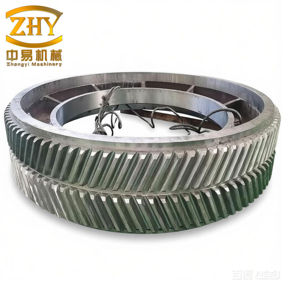
In this thesis, I focus on the traction transmission system of a high-speed electric multiple unit (EMU). The herringbone gear, with its unique symmetric structure, offers lower axial force, higher load capacity, smaller deformation, larger contact ratio, and smoother transmission. These advantages make it widely applicable in high-speed rotating machinery. Therefore, I take the traction transmission device of a certain EMU as the research object and explore the application of herringbone gears in EMU gear transmission. I conduct a comprehensive simulation analysis and exploratory research on the EMU traction herringbone gear transmission system. The main research contents are summarized below.
1. Model Establishment and Static Analysis of the EMU Traction Herringbone Gear Transmission System
I establish a simulation model of the EMU traction herringbone gear transmission system using Romax Designer software, based on the relevant parameters of a high-speed EMU driving device. The transmission principle includes: traction motor → coupling → pinion → gear → wheelset. The main technical parameters of the EMU are listed in the following tables.
Table 1: Main operating conditions of the EMU
| Condition | Motor torque (N·m) | Motor speed (r/min) | Motor power (kW) | Vehicle speed (km/h) | Time proportion |
|---|---|---|---|---|---|
| Starting | 3070 | 360 | 116 | 5 | 5% |
| Continuous 1 | 2400 | 1200 | 301 | 100 | 10% |
| Continuous 2 | 1700 | 2400 | 427 | 200 | 15% |
| High speed 1 | 1430 | 4100 | 613 | 350 | 30% |
| High speed 2 | 1050 | 5700 | 617 | 400 | 15% |
Table 2: Basic parameters of the herringbone gear pair
| Parameter | Symbol | Pinion | Gear | Unit |
|---|---|---|---|---|
| Number of teeth | z | 35 | 85 | — |
| Helix angle | β | 25 | deg | |
| Normal pressure angle | αn | 20 | deg | |
| Normal module | mn | 6 | mm | |
| Center distance | a | 380 | mm | |
| Face width | b | 68 | 66 | mm |
I apply the load spectrum according to ISO standards and only consider the forward rotation of the motor. The static analysis yields the shaft deflection, gear contact stress, bending stress, contact ratio, and mesh misalignment. The shaft deflection amplitude is 1.141 mm. The contact and bending stresses under different operating conditions are summarized in Table 3.
Table 3: Contact and bending stresses of the driven herringbone gear wheels
| Operating condition | Starting | Continuous 1 | Continuous 2 | High speed 1 | High speed 2 |
|---|---|---|---|---|---|
| Gear set 1 contact stress (MPa) | 769 | 634 | 597 | 545 | 511 |
| Gear set 1 bending stress (MPa) | 283 | 195 | 176 | 141 | 129 |
| Gear set 2 contact stress (MPa) | 711 | 586 | 553 | 519 | 479 |
| Gear set 2 bending stress (MPa) | 262 | 178 | 163 | 128 | 117 |
The herringbone gear is treated as two symmetric helical gear pairs with opposite helix directions. The static results show that the contact stresses of the left and right tooth flanks differ by less than 60 MPa and bending stresses by less than 30 MPa. This confirms the feasibility of simplifying the herringbone gear into two single helical gear pairs in the early stage of analysis. The maximum mesh misalignment of the herringbone gear is 26.88 µm.
2. Herringbone Gear Modification
The herringbone gear is subject to manufacturing errors and elastic deformation under load, which reduces transmission accuracy. Gear modification, including tooth profile modification and lead (helix) modification, is an effective way to reduce transmission errors and improve load distribution. I first introduce the basic principles of profile modification and lead modification. The gear meshing impact is caused by the deviation of the base pitch on the actual meshing line. The load distribution in a meshing cycle changes from 40% to 100% between single and double tooth contact zones, leading to vibration and noise. The maximum profile modification amount can be estimated using the ISO formula:
$$ \Delta_{max} = \frac{F_t K_A}{b C_\gamma \varepsilon_\alpha} $$ (1)
where \(F_t\) is the tangential force, \(K_A\) is the application factor, \(b\) is the face width, \(C_\gamma\) is the mesh stiffness, and \(\varepsilon_\alpha\) is the transverse contact ratio. The modification curve follows a power law:
$$ \Delta(x) = \Delta_{max} \left(\frac{x}{L}\right)^e $$ (2)
where \(e\) ranges from 1 to 2 depending on the curve type.
For the herringbone gear modification optimization, I use the second-generation genetic algorithm (GA) in Romax Designer. The optimization process includes defining the population (size 20, generations 5), selecting design variables (lead crown, lead slope, profile crown, profile slope), specifying operating conditions (all five EMU operating conditions), and setting optimization targets (transmission error first harmonic 0–1 µm and reduced maximum face load). The genetic algorithm iterates through crossover and mutation to minimize the objective function. The optimal modification parameters are shown in Table 4.
Table 4: Optimal modification parameters from second-generation GA
| Tooth flank | Lead crown (µm) | Lead slope (µm) | Profile crown (µm) | Profile slope (µm) |
|---|---|---|---|---|
| Right flank | 0.39 | 14.33 | 6.72 | 12.71 |
| Left flank | 0.17 | 14.63 | 5.98 | 11.39 |
Based on these parameters, I perform both lead modification and profile modification on the herringbone gear. The lead modification curve starts at 5.1 mm (bottom) and 28.9 mm (top), while the profile modification starts at 10.18° (root) and 33.13° (tip). After modification, the contact stress, unit length load, and transmission error are compared with those before modification.
Table 5: Contact stress comparison before and after modification (right flank)
| Operating condition | Starting | Continuous 1 | Continuous 2 | High speed 1 | High speed 2 |
|---|---|---|---|---|---|
| Before (MPa) | 772 | 634 | 597 | 547 | 511 |
| After (MPa) | 716 | 582 | 540 | 513 | 474 |
| Reduction | 7.3% | 8.2% | 9.5% | 6.2% | 7.2% |
Table 6: Unit length load comparison before and after modification
| Operating condition | Starting | Continuous 2 | High speed 1 |
|---|---|---|---|
| Before (N/mm) | 531 | 366 | 302 |
| After (N/mm) | 461 | 318 | 274 |
| Reduction | 13.2% | 13.1% | 9.3% |
Table 7: Transmission error peak comparison before and after modification
| Operating condition | Starting | Continuous 2 | High speed 1 |
|---|---|---|---|
| Before (µm) | 64.4 | 36.3 | 30.0 |
| After (µm) | 41.3 | 27.5 | 23.6 |
| Reduction | 35.9% | 24.2% | 21.3% |
The modification results demonstrate that the herringbone gear modification effectively reduces contact stress and transmission error while increasing the contact area. This improves the load-carrying capacity and meshing smoothness of the herringbone gear transmission system.
3. Dynamic Analysis of the Herringbone Gear Transmission System
I analyze the dynamic characteristics of the EMU traction herringbone gear transmission system, including modal flexibility, dynamic mesh stiffness, modal shapes, and vibration responses. The gear mesh stiffness varies periodically due to the alternating single and double tooth contact. The total flexibility of the herringbone gear pair is the sum of the flexibilities of both meshing gear sets:
$$ \delta = \delta_{p1} + \delta_{g1} + \delta_{p2} + \delta_{g2} = \frac{1}{k_{p1}} + \frac{1}{k_{g1}} + \frac{1}{k_{p2}} + \frac{1}{k_{g2}} $$ (3)
Then the combined mesh stiffness is:
$$ k = \frac{1}{\delta} $$ (4)
Using Romax, I compute the first 40 natural frequencies and modal flexibilities. The maximum modal flexibility occurs at the 16th order with a value of \(1.33 \times 10^{-4}\) µm/N at a frequency of 1873.1 Hz. The modal flexibility curves for the left and right herringbone gear sets show a similar trend with respect to frequency. Table 8 lists selected modal flexibility values and corresponding natural frequencies.
Table 8: Representative modal flexibility and natural frequency of the system
| Order | Natural frequency (Hz) | Modal flexibility (µm/N) |
|---|---|---|
| 3 | 238.6 | 4.77e-5 |
| 6 | 470.8 | 2.35e-5 |
| 9 | 716.5 | 1.09e-4 |
| 16 | 1873.1 | 1.33e-4 |
| 21 | 2624.3 | 3.76e-5 |
| 27 | 3436.2 | 1.81e-5 |
The dynamic mesh stiffness of the herringbone gear pair is analyzed at rated power. The stiffness reaches a maximum of \(1.5 \times 10^6\) N/mm at a shaft frequency of 1824 Hz, after which it stabilizes around \(4.78 \times 10^5\) N/mm. The mesh phase also fluctuates and then settles within 15° at high frequencies.
The modal shapes of the transmission system are investigated at the orders with high flexibility. The 3rd mode shows a significant input shaft bending causing gear misalignment; the 6th and 9th modes show torsional bending of the output shaft; the 16th mode corresponds to the normal rated condition with relatively small gear misalignment; the 21st and 27th modes exhibit larger gear meshing impact due to high-speed rotation.
For the vibration response analysis, I study the dynamic contact load and displacement of the four supporting bearings under harmonic excitations up to the 35th order. Table 9 lists the maximum dynamic contact loads of the bearings.
Table 9: Maximum dynamic contact load of bearings
| Bearing | Maximum contact load (N) | Approximate frequency (Hz) |
|---|---|---|
| Bearing 1 | 1.33e3 | 1000 |
| Bearing 2 | 5.5e2 | 300 |
| Bearing 3 | 1.06e3 | 300 |
| Bearing 4 | 1.62e3 | 830 |
The dynamic displacement of bearing 1 has the largest peak of 1.98 µm, while bearings 2 and 3 show smaller peaks around 0.36 µm. After 1000 Hz, all displacements stabilize. The response waterfall diagrams demonstrate that the vibration acceleration increases with both response frequency and input shaft speed. The maximum acceleration response occurs at the 35th harmonic with a value of \(17.18 \, \text{m/s}^2\).
4. Fatigue Life and Scuffing Analysis of the Herringbone Gear Transmission System
Fatigue damage and life assessment are critical for the reliability of the EMU traction herringbone gear transmission system. I employ the Miner linear cumulative damage rule, rain-flow counting method, and local stress-strain method to evaluate fatigue damage. The Miner criterion is expressed as:
$$ D = \sum_{i=1}^{n} \frac{n_{\sigma i}}{N_{\sigma i}} = 1 $$ (5)
where \(n_{\sigma i}\) is the number of cycles at stress level \(\sigma_i\) and \(N_{\sigma i}\) is the corresponding fatigue life.
The rain-flow counting method extracts closed hysteresis loops from the stress-time history, enabling cycle counting for variable amplitude loading. The local stress-strain method accounts for plasticity and load sequence effects.
For the herringbone gear material 18CrNiMo7-6 after carburizing and quenching, the contact fatigue strength limit is 1500 MPa and the bending fatigue strength limit is 500 MPa. The combined safety factor is above 1.5 for all operating conditions, satisfying strength requirements.
The scuffing analysis is based on the Blok flash temperature criterion. The maximum flash temperature is:
$$ \theta_{flmax} = \theta_{Bmax} – \theta_{M} $$ (6)
where \(\theta_{Bmax}\) is the maximum contact temperature and \(\theta_{M}\) is the tooth body temperature. The scuffing safety factor is calculated by:
$$ S_B = \frac{\theta_S – \theta_{oil}}{\theta_B – \theta_{oil}} \cdot \frac{X_\Gamma}{X_\Gamma} $$ (7)
The calculated scuffing parameters for both flanks of the herringbone gear are shown in Table 10.
Table 10: Flash temperature scuffing parameters for the herringbone gear
| Parameter | Left flank | Right flank |
|---|---|---|
| Lubricant temperature (°C) | 60 | 60 |
| Body temperature (°C) | 62.465 | 62.545 |
| Maximum flash temperature (°C) | 53.697 | 55.391 |
| Maximum contact temperature (°C) | 116.162 | 117.936 |
| Scuffing temperature (°C) | 328.707 | 328.707 |
| Scuffing safety factor | 4.785 | 4.638 |
The scuffing safety factors are well above 1, indicating sufficient anti-scuffing capability. However, under high-speed and heavy-load conditions, the instantaneous temperature rise may reduce oil film thickness, so a higher-viscosity lubricant is recommended.
For the rolling bearings, I analyze the fatigue life and damage according to ISO 281:2007. The accumulated damage of the four bearings under the rated spectrum is listed in Table 11.
Table 11: Bearing damage and rated life (ISO 281)
| Bearing | Damage (%) | L10 life (h) |
|---|---|---|
| Bearing 1 | 6.137e-3 | 16294 |
| Bearing 2 | 4.239e-5 | 2.359e6 |
| Bearing 3 | 5.999e-6 | 1.667e7 |
| Bearing 4 | 4.439e-3 | 22527 |
Bearing 1 has the largest damage, located near the input pinion. Its fatigue life is 16294 hours, which is greater than the required 11000 hours under ideal operating conditions. I further analyze the contact load distribution of bearing 1. The maximum raceway load is 23102.4 N at a contact angle of 139.741°. The maximum raceway contact stress is 2411 MPa. Only the left seven rolling elements are loaded. The contact stress distribution along the circumferential direction is shown in Table 12.
Table 12: Contact stress distribution of bearing 1 rolling elements
| Angular position (deg) | 61.49 | 85.49 | 109.49 | 133.49 | 157.49 | 181.49 | 205.49 | 229.49 |
|---|---|---|---|---|---|---|---|---|
| Inner raceway stress (MPa) | 199 | 1532 | 2144 | 2411 | 2376 | 2034 | 1308 | 198 |
| Outer raceway stress (MPa) | 0 | 1342 | 1870 | 2100 | 2070 | 1775 | 1147 | 0 |
The fatigue life of the herringbone gear and rolling bearings satisfies the design requirements under the assumed operating conditions. Periodic maintenance and proper lubrication are essential to prevent premature failures such as pitting, scuffing, and spalling.
Conclusion
In this work, I present a comprehensive simulation study of the EMU traction herringbone gear transmission system. The main conclusions are:
(1) The static analysis reveals that the herringbone gear experiences a maximum contact stress of 769 MPa and a maximum bending stress of 283 MPa under the starting condition. The total contact ratio is 2.254, which ensures smooth transmission. The maximum mesh misalignment is 26.88 µm.
(2) The second-generation genetic algorithm successfully optimizes the modification parameters for the herringbone gear. After modification, the transmission error is reduced by up to 35.9%, the unit length load is reduced by up to 15.5%, and the contact stress is reduced by up to 9.5%. The modification dramatically improves the meshing performance of the herringbone gear.
(3) The dynamic analysis shows that the maximum modal flexibility of the herringbone gear system occurs at 1873.1 Hz with a value of \(1.33 \times 10^{-4}\) µm/N. The dynamic mesh stiffness reaches its maximum at 1824 Hz. The bearing dynamic loads and displacements are frequency-dependent, with the largest response appearing near the resonant frequencies of the system.
(4) The fatigue and scuffing analysis confirms that both the herringbone gear and the rolling bearings have sufficient fatigue life. The scuffing safety factors are 4.785 and 4.638 for the left and right flanks, respectively. The most damaged bearing has a life of 16294 hours, which exceeds the required 11000 hours under ideal conditions.
This study provides a useful reference for the design and optimization of herringbone gear transmission systems in high-speed EMUs. Future work should include experimental verification and consider more complex operating conditions such as reverse rotation, heavy loads, and track irregularities.