
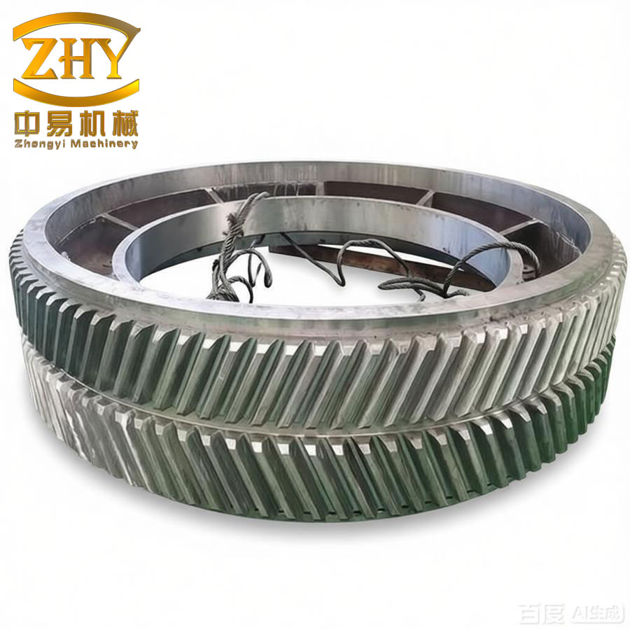
Herringbone gears are widely employed in high-speed and heavy-duty transmission systems, such as marine propulsion, aerospace, and wind turbines, due to their high load-carrying capacity, high redundancy, and the ability to cancel axial thrust forces. In practical engineering, the gear tooth surfaces may suffer from fatigue failures, especially under harsh lubrication conditions and severe load fluctuations. Among the common failure modes, tooth root cracks and surface pitting often occur simultaneously, resulting in a coupled damage condition that significantly affects the time-varying mesh stiffness and the dynamic behavior of the whole gear transmission system. In this work, I focus on the two-stage herringbone gear transmission system with crack-pitting coupling. I propose an improved analytical model for calculating the time-varying mesh stiffness of herringbone gears with both crack and pitting damage, considering the effect of the gear root relief groove. Moreover, I establish a 48-degree-of-freedom (DOF) coupled dynamic model of the two-stage herringbone gear system that incorporates bending, torsion, axial, and pendulum motions. The vibration responses under different crack-pitting coupling levels are investigated, and experimental tests are carried out to validate the theoretical model.
In the following sections, I first present the analytical method for the time-varying mesh stiffness of a herringbone gear pair with crack-pitting coupling. Then, I describe the establishment of the 48-DOF dynamic model. Next, I discuss the simulated vibration responses under different damage severities. After that, I provide the experimental verification. Finally, I present conclusions and future perspectives.
1. Time-Varying Mesh Stiffness of Herringbone Gear with Crack-Pitting Coupling
The time-varying mesh stiffness (TVMS) is one of the most critical internal excitation sources in gear dynamics. For herringbone gears, the contact line length varies with time due to the helix angle and the existence of the relief groove. In my analysis, I use the potential energy method combined with the slicing technique. Each tooth is modeled as a variable-cross-section cantilever beam, and the gear is divided into many thin slices along the face width direction. Each slice is treated as an equivalent spur gear slice. For each slice, the total mesh stiffness \(k_{mi}\) can be expressed as:
$$
\frac{1}{k_{mi}} = \frac{1}{k_{h,i}} + \frac{1}{k_{b1,i}} + \frac{1}{k_{s1,i}} + \frac{1}{k_{a1,i}} + \frac{1}{k_{f1,i}} + \frac{1}{k_{b2,i}} + \frac{1}{k_{s2,i}} + \frac{1}{k_{a2,i}} + \frac{1}{k_{f2,i}}
$$
where \(k_{h}\) is the Hertzian contact stiffness, \(k_{b}\) is the bending stiffness, \(k_{s}\) is the shear stiffness, \(k_{a}\) is the axial compressive stiffness, and \(k_{f}\) is the gear body stiffness. Subscripts 1 and 2 denote the pinion and the gear, respectively. The total mesh stiffness of a herringbone gear pair is obtained by summing the contributions of all engaged slices:
$$
k_{m} = \sum_{j=1}^{N_s} k_{mj}
$$
where \(N_s\) is the number of slices in contact at the same time.
In the calculation, the tooth profile is described by the involute curve. Since the root circle radius may be larger or smaller than the base circle radius, two cases are considered. In Case I, when the base circle radius is larger than the root circle radius, the tooth is modeled as a cantilever beam fixed at the base circle. In Case II, when the base circle radius is smaller than the root circle radius, the tooth is modeled as a cantilever beam fixed at the root circle. The effective cross-sectional area \(A_x\) and the area moment of inertia \(I_x\) are functions of the distance \(x\) from the fixed section to the loading point. By integrating the strain energy expressions, I obtain the bending, shear, and axial compressive stiffness components for healthy gears.
2. Analytical Model for Crack-Pitting Coupled Herringbone Gear
Gear pitting is simulated as cylindrical pits on the tooth flank. The pit center is projected onto the instantaneous contact line. The geometry of the pit is defined by the radius \(R_{sp}\), the depth \(d_{sp}\), and the location along the face width \(y_{sp}\). Pitting reduces the effective contact line length and the load-carrying area. The effective contact line length as a function of time is denoted by \(l_d(t)\). The Hertzian contact stiffness for the pitted gear is then written as:
$$
k_{hi} = \frac{1.275 E^{*0.9} l_{d}(t)^{0.8} F_{i}^{0.1}}{1.275}
$$
Actually, a more common formulation is:
$$
k_{hi} = 1.275 E^{*0.9} l_{d}^{0.8} F_{i}^{0.1}
$$
where \(E^{*}\) is the equivalent elastic modulus and \(F_i\) is the contact force carried by the \(i\)-th tooth pair.
For the cross-section of the pitted gear, the effective area and moment of inertia are modified by subtracting the damaged portions. I define \(\Delta A_x\), \(\Delta I_x\), and \(\Delta l_x\) as the reductions in area, moment of inertia, and contact line length due to pitting. These terms are computed from the pit radius and the intersection of the pit with the gear cross-section.
Tooth root cracks are modeled as straight cracks with depth \(q_i\) and a propagation angle \(\xi\) measured from the tooth centerline. Four crack levels are considered: 10% (slight), 30% (transition), 50% (moderate), and 70% (severe). The presence of a crack reduces the effective cross-sectional area and the moment of inertia, which directly influences the bending and shear stiffness values.
In the coupled crack-pitting case, the interaction between the crack and pitting damage must be considered. Depending on the relative positions of the crack tip and the pitting area, four different scenarios are distinguished:
Case 1: The crack is shallow and entirely above the pitting region. Both damages independently contribute to the reduction in stiffness.
Case 2: The crack tip reaches the pitting region. The crack and pitting overlap, and the combined damaged area is calculated by considering the union of the two defect shapes.
Case 3: The crack passes beyond the pitting region. The crack dominates the stiffness reduction, but pitting still reduces the contact line length.
Case 4: The crack is very deep and the effective cross-section is completely determined by the crack geometry, while pitting only affects the local contact line.
For each case, I derive the effective \(A_x\) and \(I_x\) used in the energy integral. For example, in Case 1, the effective area is:
$$
A_x =
\begin{cases}
h_x + h_{x1} & \text{if } 0 \le x < d_l \\
h_x + h_{x1} – \Delta A_{sp} & \text{if } d_l \le x < d_{spi} \\
h_x + h_{x1} – \Delta A_{sp} & \text{if } d_{spi} \le x \le d_{spo} \\
h_x + h_{x1} & \text{if } x > d_{spo}
\end{cases}
$$
Similarly, the moment of inertia is modified. By substituting these terms into the potential energy expressions, I obtain the analytical expressions for the coupled stiffness. The final mesh stiffness of the herringbone gear pair is then obtained by summing over all slices in contact.
3. Effect of Crack-Pitting Coupling on TVMS
I apply the proposed analytical model to a specific herringbone gear pair. The gear parameters are listed in Table 1.
| Parameter | 1st stage pinion | 1st stage gear | 2nd stage pinion | 2nd stage gear |
|---|---|---|---|---|
| Number of teeth | 25 | 60 | 25 | 75 |
| Module (mm) | 2 | 2 | 2 | 2 |
| Helix angle (deg) | 15 | 15 | 15 | 15 |
| Pressure angle (deg) | 20 | 20 | 20 | 20 |
| Mass (kg) | 2 | 5 | 2 | 5 |
| Relief groove width (mm) | 3 | 3 | 3 | 3 |
| Relief groove radius (mm) | 26 | 58 | 26 | 72 |
| Total face width (mm) | 43 | 43 | 43 | 43 |
| Bore radius (mm) | 20 | 20 | 20 | 20 |
| Poisson’s ratio | 0.3 | 0.3 | 0.3 | 0.3 |
| Moment of inertia (kg·m²) | 5 | 10 | 5 | 10 |
The input speed is 1800 r/min and the input torque is 200 N·m. I first investigate the influence of the relief groove width on the TVMS of a healthy herringbone gear pair. Table 2 lists the average mesh stiffness values for different relief groove widths.
| Relief groove width (mm) | Average mesh stiffness (×10⁹ N/m) |
|---|---|
| 0 | 2.58 |
| 5 | 2.61 |
| 10 | 2.67 |
| 15 | 2.74 |
The results show that increasing the relief groove width slightly increases the total mesh stiffness, since the gear body becomes stiffer. However, the variation is relatively small compared with the effect of tooth damage.
Next, I simulate four pitting levels: slight, transition, moderate, and severe. For slight pitting, the pit radius is \(R_{sp}=0.3\) mm and the depth is \(d_{sp}=0.3\) mm, with 3 pits. Transition pitting has the same geometry but 6 pits. Moderate pitting has an increased radius of 0.4 mm with 6 pits. Severe pitting has two rows of pits with radius 0.4 mm, resulting in 12 pits. Figure 1 (not shown here) illustrates the equivalent pitting models. The TVMS curves show that pitting causes local reductions in mesh stiffness, and the reductions become deeper and wider as the pitting severity increases.
For the crack-pitting coupling study, I combine the above pitting levels with crack levels of 10%, 30%, 50%, and 70%. Table 3 summarizes the percentage reductions in mesh stiffness at the resonance point, along with the corresponding influence rates of pitting and crack.
| Crack-pitting coupling level | Total stiffness reduction (%) | Pitting influence rate (%) | Crack influence rate (%) |
|---|---|---|---|
| Slight crack + slight pitting | 2.01 | 82.59 | 17.41 |
| Transition crack + slight pitting | 2.89 | 57.44 | 46.37 |
| Moderate crack + slight pitting | 4.66 | 35.62 | 65.45 |
| Severe crack + slight pitting | 7.92 | 20.96 | 85.35 |
| Slight crack + transition pitting | 3.95 | 91.14 | 8.86 |
| Transition crack + transition pitting | 4.85 | 74.27 | 27.63 |
| Moderate crack + transition pitting | 5.79 | 62.18 | 52.68 |
| Severe crack + transition pitting | 9.29 | 38.75 | 72.73 |
| Slight crack + moderate pitting | 5.46 | 93.59 | 6.41 |
| Transition crack + moderate pitting | 6.08 | 84.05 | 22.04 |
| Moderate crack + moderate pitting | 6.98 | 73.21 | 43.70 |
| Severe crack + moderate pitting | 10.40 | 49.13 | 65.00 |
| Slight crack + severe pitting | 6.08 | 83.88 | 16.12 |
| Transition crack + severe pitting | 9.05 | 56.35 | 49.28 |
| Moderate crack + severe pitting | 10.40 | 49.04 | 65.00 |
| Severe crack + severe pitting | 17.60 | 28.98 | 82.39 |
From Table 3, it is clear that when the pitting severity is fixed, the pitting influence rate decreases as the crack level increases, while the crack influence rate increases. In the early stage, pitting dominates the stiffness reduction; later, crack becomes the dominant factor, but pitting still contributes by reducing the contact line length.
4. Finite Element Validation of TVMS
To verify the analytical model, I use the finite element method (FEM) to compute the TVMS of the herringbone gear pair with crack-pitting coupling. A three-dimensional finite element model is built in ANSYS. The gear bodies are meshed with tetrahedral elements, and the contact faces are refined locally around the pitting areas and the crack path. The pinion is driven at a constant angular velocity of 10 rad/s, and the gear is loaded with a torque of 200 N·m. The contact is simulated with surface-to-surface contact elements. The total deformation and contact force are extracted to calculate the mesh stiffness.
For validation, I compare the analytical and FEM results for healthy gears and for three coupling levels: slight crack–slight pitting, transition crack–transition pitting, and moderate crack–moderate pitting. The average errors at the maximum deviation points are within 2.5%, as illustrated in Table 4.
| Condition | Analytical average stiffness (×10⁹ N/m) | FEM average stiffness (×10⁹ N/m) | Relative error (%) |
|---|---|---|---|
| Healthy | 2.98 | 3.02 | 1.34 |
| Slight crack – slight pitting | 2.87 | 2.91 | 1.39 |
| Transition crack – transition pitting | 2.71 | 2.76 | 1.85 |
| Moderate crack – moderate pitting | 2.52 | 2.58 | 2.33 |
The good agreement confirms the effectiveness of the analytical method for calculating the TVMS of herringbone gears with crack-pitting coupling.
5. Dynamic Model of the Two-Stage Herringbone Gear System
I establish a 48-DOF lumped-parameter dynamic model of the two-stage herringbone gear transmission system. The model includes translational displacements in the \(x\), \(y\), and \(z\) directions, as well as rotational displacements around the \(x\) and \(y\) axes for each gear. In addition, the torsional degree of freedom around the \(z\)-axis is considered for each gear. Thus, for four gears in the two stages, there are \(4 \times 6 = 24\) DOFs. Furthermore, the left and right helical gear bodies of each herringbone gear are treated as two independent lumped masses connected by a torsional stiffness representing the relief groove. This yields \(8 \times 6 = 48\) DOFs in total.
The dynamic model is shown in Figure 2 (not reproduced here). The equations of motion for each gear are derived using Newton’s second law. For the left pinion of the first stage, the equations can be written as:
$$
\begin{aligned}
m_{AL}^1 \ddot{x}_{AL}^1 &= k_x^{AL1} f_x + c_x^{AL1} \dot{f}_x + \cdots + k_m^L f_L \cos\beta \sin\psi + c_m^L \dot{f}_L \cos\beta \sin\psi + F_{fx}^{AL1} \\
m_{AL}^1 \ddot{y}_{AL}^1 &= k_y^{AL1} f_y + c_y^{AL1} \dot{f}_y + \cdots – k_m^L f_L \cos\beta \cos\psi – c_m^L \dot{f}_L \cos\beta \cos\psi + F_{fy}^{AL1} \\
m_{AL}^1 \ddot{z}_{AL}^1 &= k_z^{AL1} z_{AL}^1 + c_z^{AL1} \dot{z}_{AL}^1 + \cdots – k_m^L f_L \sin\beta – c_m^L \dot{f}_L \sin\beta \\
I_{x,AL}^1 \ddot{\theta}_{x,AL}^1 + k_{\theta x}^{AL1} \theta_{x,AL}^1 + c_{\theta x}^{AL1} \dot{\theta}_{x,AL}^1 &= – R_{AL}^1 k_m^L f_L \sin\beta \sin\psi – R_{AL}^1 c_m^L \dot{f}_L \sin\beta \sin\psi + T_{fx}^{AL1} \\
I_{y,AL}^1 \ddot{\theta}_{y,AL}^1 + k_{\theta y}^{AL1} \theta_{y,AL}^1 + c_{\theta y}^{AL1} \dot{\theta}_{y,AL}^1 &= + R_{AL}^1 k_m^L f_L \sin\beta \cos\psi + R_{AL}^1 c_m^L \dot{f}_L \sin\beta \cos\psi + T_{fy}^{AL1} \\
I_{z,AL}^1 \ddot{\theta}_{z,AL}^1 + k_{\theta z}^{AL1} \theta_{z,AL}^1 + c_{\theta z}^{AL1} \dot{\theta}_{z,AL}^1 &= T_{AL}^1 – T_f^1 + \cdots
\end{aligned}
$$
where \(f_L\) and \(f_R\) are the relative displacements along the line of action for the left and right gear meshes, respectively. They are defined as:
$$
f_L = (x_{AL}^1 – x_{DL}^1)\sin\psi + (y_{AL}^1 – y_{DL}^1)\cos\psi + (z_{AL}^1 – z_{DL}^1) + R_{AL}^1 \theta_{z,AL}^1 + R_{DL}^1 \theta_{z,DL}^1 – e_L
$$
$$
f_R = (x_{AR}^1 – x_{DR}^1)\sin\psi + (y_{AR}^1 – y_{DR}^1)\cos\psi + (z_{AR}^1 – z_{DR}^1) + R_{AR}^1 \theta_{z,AR}^1 + R_{DR}^1 \theta_{z,DR}^1 – e_R
$$
The time-varying mesh stiffness \(k_m^L(t)\) and \(k_m^R(t)\) are obtained from the analytical TVMS model described earlier. In the dynamic model, the TVMS is expanded into Fourier series:
$$
k_m^p(t) = k_{avg}^p \left[ 1 – \sum_{l=1}^{L} \varepsilon_l \cos(l\omega_m^p t) \right], \quad p = L, R
$$
where \(k_{avg}^p\) is the average mesh stiffness, \(\varepsilon_l\) is the fluctuation coefficient, and \(\omega_m^p\) is the meshing angular frequency. The comprehensive transmission error is similarly expressed as:
$$
e_p(t) = e_m^p + \sum_{l=1}^{L} e_l^p \sin(l\omega_m^p t)
$$
The meshing damping \(c_m^p\) is calculated by:
$$
c_m^p = 2 \zeta \sqrt{k_{avg}^p / m_{eq}^p}
$$
where \(m_{eq}^p\) is the equivalent mass of the gear pair and \(\zeta\) is the damping ratio.
The friction forces and friction torques are computed using the elastohydrodynamic lubrication (EHL) friction coefficient model. The friction coefficient \(\mu\) is expressed as:
$$
\mu = \exp\left[ c_1 + c_2 \ln(SR) + c_3 \ln(P_h) + c_4 \ln(v_0) + c_5 \ln(S) + c_6 (SR)^2 + c_7 (P_h)^2 + c_8 (v_0)^2 + c_9 (S)^2 \right]
$$
Table 5 lists the empirical constants used in the friction model.
| c1 | c2 | c3 | c4 | c5 | c6 | c7 | c8 | c9 |
|---|---|---|---|---|---|---|---|---|
| -8.92 | 1.05 | 1.05 | -0.34 | 2.82 | -0.11 | 0.74 | -0.37 | 0.64 |
The supporting stiffness and damping values are given in Table 6.
| Parameter | Value |
|---|---|
| Support stiffness (N/m) | 1×10⁹ |
| Support damping (N·s/m) | 1×10⁵ |
| Torsional stiffness (N·m/rad) | 1×10⁷ |
| Torsional damping (N·m·s/rad) | 1×10³ |
| Damping ratio \(\zeta\) | 0.05 |
6. Vibration Response Analysis
By substituting the crack-pitting coupled TVMS into the 48-DOF dynamic model, I solve the differential equations using the fourth-order Runge-Kutta method with a fixed time step. The simulations are performed for healthy gears and for four crack-pitting coupling levels: 10%, 30%, 50%, and 70%. For the first-stage gear pair, the pinion rotation frequency is \(f_{A1} = 30\) Hz, and the gear mesh frequency is \(f_{m1} = 2400\) Hz. For the second-stage gear pair, the pinion rotation frequency is \(f_{A2} = 12.5\) Hz, and the mesh frequency is \(f_{m2} = 1000\) Hz.
Figure 3 (not shown) displays the time-domain displacement signals of the first-stage gear pair under different coupling levels. The healthy gear pair shows a steady periodic vibration with an amplitude range from \(-37.3\) μm to \(-36.3\) μm. When the crack-pitting coupling is introduced, the displacement jumps near the damaged region. The amplitude values for the first-stage gear pair are summarized in Table 7.
| Crack-pitting coupling level | Amplitude (μm) | Increase relative to healthy (%) |
|---|---|---|
| Healthy | 0.50 | – |
| 10% | 0.60 | 20 |
| 30% | 0.71 | 42 |
| 50% | 0.84 | 68 |
| 70% | 1.16 | 132 |
Similarly, for the second-stage gear pair, the healthy amplitude is 1.25 μm. The amplitudes under different coupling levels are listed in Table 8.
| Crack-pitting coupling level | Amplitude (μm) | Increase relative to healthy (%) |
|---|---|---|
| Healthy | 1.25 | – |
| 10% | 1.77 | 41.6 |
| 30% | 2.43 | 94.4 |
| 50% | 3.57 | 185.6 |
| 70% | 6.02 | 381.6 |
It is obvious that the second-stage gear pair exhibits much larger vibration amplitudes than the first-stage gear pair under the same crack-pitting coupling level. This indicates that the vibration energy is concentrated at the high-speed stage in a two-stage herringbone gear transmission system when damage exists.
In the frequency domain, the healthy system shows distinct components at the mesh frequency and its harmonics, i.e., \(f_m\), \(2f_m\), and \(3f_m\), with no obvious sidebands. For the damaged gear pairs, sidebands appear around the mesh frequencies. The sideband spacing is equal to the rotation frequency of the damaged gear. For the first-stage gear pair, the sideband spacing is \(\Delta f = 30\) Hz. For the second-stage gear pair, the sideband spacing is \(\Delta f = 12.5\) Hz. As the crack-pitting coupling severity increases, the amplitudes of the sidebands grow significantly, which can be used as a diagnostic indicator.
Table 9 compares the maximum sideband amplitudes around \(2f_m\) for the first-stage and second-stage gear pairs.
| Crack-pitting coupling level | 1st stage sideband amplitude (×10⁻⁶ m) | 2nd stage sideband amplitude (×10⁻⁶ m) |
|---|---|---|
| Healthy | 0.02 | 0.03 |
| 10% | 0.12 | 0.18 |
| 30% | 0.25 | 0.42 |
| 50% | 0.44 | 0.83 |
| 70% | 0.78 | 1.65 |
The results show a monotonic increase in sideband amplitudes with increasing damage severity, which is consistent with the physical expectation that crack-pitting coupling introduces periodic impact excitation at the rotating frequency.
7. Experimental Verification
To validate the theoretical predictions, I conduct vibration tests on a two-stage herringbone gear test rig. The test rig consists of an AC servo motor, a gearbox, acceleration sensors, a torque sensor, a magnetic powder brake, and a data acquisition system. The input speed is set to 1800 r/min and the torque to 200 N·m. The acceleration signals are collected from the gearbox housing and then integrated twice in the frequency domain to obtain displacement signals.
For the experimental study, I manufacture herringbone gears by cutting wide-face helical gears into narrow-face gears and then connecting the left and right helical gears with dowel pins. Different crack-pitting coupling levels are introduced by wire electrical discharge machining (WEDM) for cracks and electric discharge machining (EDM) for pitting. The test is repeated for healthy gears and for gears with crack-pitting coupling levels of 10%, 50%, and 70% (with 10% representing slight crack and slight pitting, 50% representing moderate crack and moderate pitting, and 70% representing severe crack and severe pitting).
Figure 5 (not shown) presents the time-domain and frequency-domain responses obtained from the experiments. For the healthy gear, the time-domain displacement is stable without obvious impacts. In the frequency domain, only the meshing frequency harmonics are visible. After introducing the crack-pitting coupling, the time-domain signals show periodic impacts with a repetition period equal to the gear rotation period. The frequency domain shows clear sidebands around the mesh frequency and its harmonics, and the sideband amplitudes increase with the damage level.
Table 10 compares the maximum vibration displacement amplitudes obtained from the theoretical simulation and the experimental tests.
| Crack-pitting coupling level | Theoretical amplitude (μm) | Experimental amplitude (μm) | Relative error (%) |
|---|---|---|---|
| Healthy | 1.25 | 1.29 | 3.2 |
| 10% | 1.77 | 1.84 | 3.8 |
| 50% | 3.57 | 3.77 | 5.3 |
| 70% | 6.02 | 6.55 | 7.5 |
The relative errors between theoretical and experimental results are within 2% to 8%. These errors are mainly caused by manufacturing tolerances, assembly misalignments, and unmodeled nonlinearities such as bearing clearance and damping variations. Nevertheless, the trends are consistent, which validates the correctness of the proposed analytical TVMS model and the 48-DOF dynamic model for the two-stage herringbone gear transmission system with crack-pitting coupling.
8. Conclusion
In this work, I have systematically investigated the vibration characteristics of a two-stage herringbone gear transmission system under crack-pitting coupling damage. The main conclusions can be drawn as follows:
(1) An improved analytical model is proposed to calculate the time-varying mesh stiffness of herringbone gears with crack-pitting coupling and a relief groove. The model considers four coupling scenarios depending on the relative positions of the crack and pitting. The results show that the relief groove width has a modest positive effect on the mesh stiffness, while crack-pitting coupling causes significant stiffness reduction. The finite element method validates the analytical model with errors below 2.5%, confirming its accuracy.
(2) The influence rates of pitting and crack vary with the coupling severity. In the early stage, pitting dominates with a contribution of 82.59% to 93.59%. In the intermediate stage, both pitting and crack have comparable influences. In the severe stage, crack dominates with a contribution of 65.00% to 85.35%, while pitting still reduces the contact line length and thus continues to affect the stiffness.
(3) A 48-DOF bending-torsion-axial-pendulum coupled dynamics model is established for the two-stage herringbone gear transmission system. The model incorporates time-varying mesh stiffness, comprehensive transmission error, friction coefficients, support stiffness, torsion stiffness, and the effect of the relief groove. The differential equations are solved using the Runge-Kutta method, and the vibration responses are obtained for healthy and damaged systems.
(4) The time-domain responses show that the crack-pitting coupling produces periodic impacts with a period equal to the rotation period of the damaged gear. As the damage severity increases, the impact amplitude increases significantly. The second-stage gear pair experiences much larger vibration amplitudes than the first-stage gear pair, indicating that the second stage is more sensitive to crack-pitting damage. The frequency-domain responses show sidebands around the mesh frequency harmonics, with the sideband spacing equal to the rotation frequency. The sideband amplitudes increase monotonically with the coupling severity, providing a useful feature for fault diagnosis.
(5) The experimental tests on a two-stage herringbone gear test rig confirm the trends predicted by the theoretical model. The relative errors between theoretical and experimental displacement amplitudes are between 2% and 8%, which validates the effectiveness of the proposed modeling approach.
This research provides a comprehensive understanding of the coupled effects of crack and pitting on the mesh stiffness and vibration behavior of herringbone gear transmission systems. The proposed method can be used for early fault detection and condition monitoring of high-power herringbone gear systems.
In the future, I plan to extend the model to consider multiple damaged gears, more complex crack propagation paths, and the influence of lubrication regimes on the dynamic responses. Furthermore, advanced signal processing techniques will be combined with the model to improve the accuracy of crack-pitting severity estimation.