
In this study, I investigate the tooth root bending stress characteristics of a multi-modulus involute worm and helical gear pair. The central motivation is that a worm and helical gear drive can replace a traditional worm and worm wheel drive in many transmission systems because the helical gear is easier to manufacture, less sensitive to assembly error, and able to maintain good lubrication conditions. However, the bending fatigue fracture of the helical gear tooth is still one of the main failure modes. When the worm and the helical gear have different modules and different pressure angles, the meshing conditions, geometric parameters, load sharing, and tooth root stress are no longer the same as those of a conventional equal-modulus worm and helical gear pair. Therefore, I derive the correct meshing condition, establish a bending stress model, evaluate the influence of the modulus ratio, and compare the analytical results with finite element simulations.
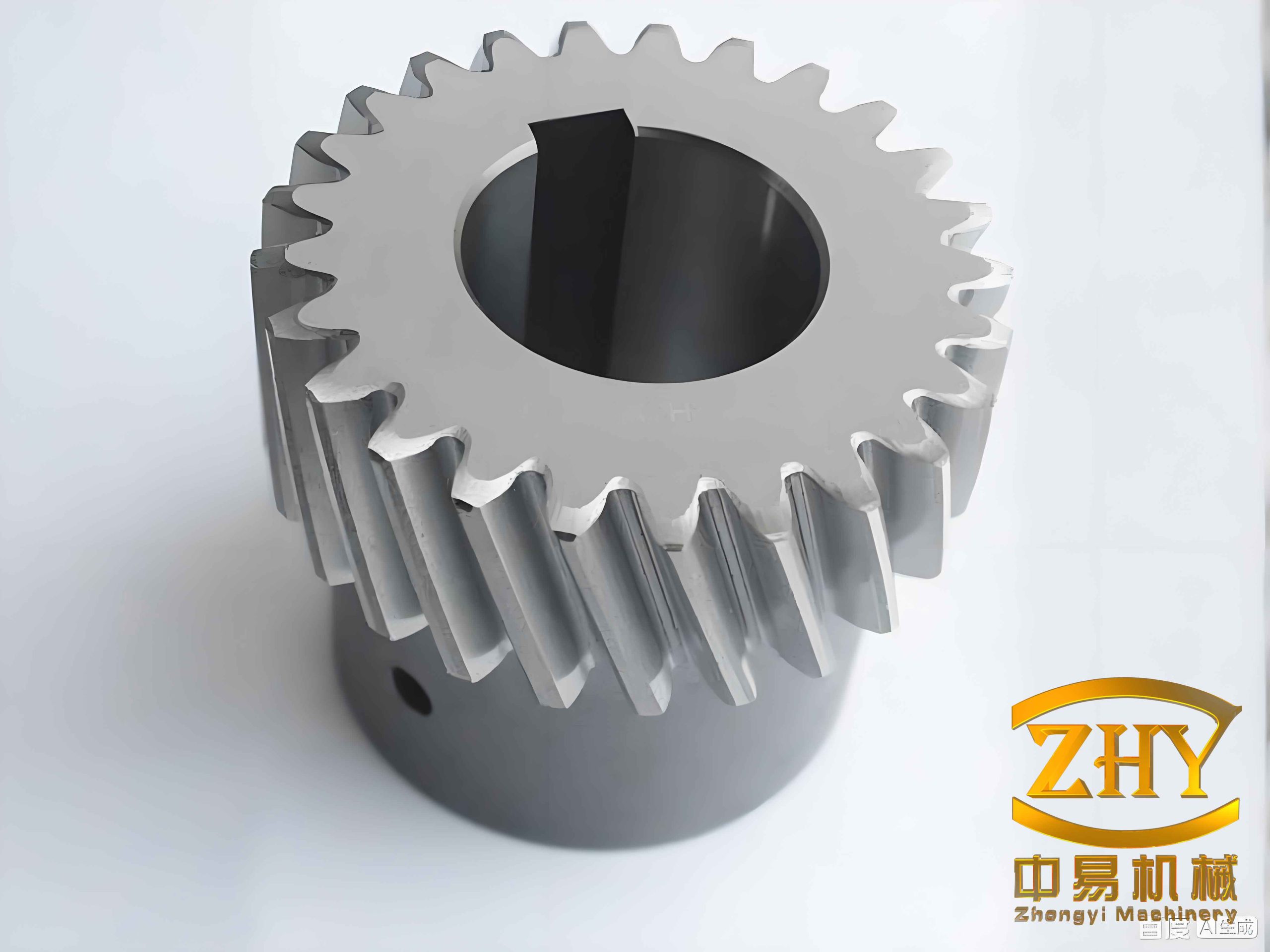
I use the term helical gear throughout this work to denote the driven gear that replaces the worm wheel. The worm is treated as a cylindrical involute worm, and the helical gear is treated as an involute helical gear. The multi-modulus condition means that the normal module and normal pressure angle of the worm are not equal to those of the helical gear. The only requirement is that the normal base pitches remain compatible. This condition allows a broader design space and can be used to reduce the tooth root bending stress of the helical gear while preserving continuous transmission.
1. Correct Meshing Condition for the Multi-Modulus Worm and Helical Gear Pair
For a traditional worm and worm wheel pair, the axial pitch of the worm must equal the transverse pitch of the worm wheel. For a worm and helical gear pair, the helical gear replaces the worm wheel, so the same principle must be expressed through the normal module and normal pressure angle. I begin with the pitch equality:
$$P_{x1}=P_{a2}$$
where \(P_{x1}\) is the axial pitch of the worm and \(P_{a2}\) is the transverse pitch of the helical gear. Since the normal module and normal pressure angle are standard design values, I rewrite the condition as:
$$m_{n1}\cos\alpha_{n1}=m_{n2}\cos\alpha_{n2}$$
Here, \(m_{n1}\) and \(m_{n2}\) are the normal modules of the worm and the helical gear, while \(\alpha_{n1}\) and \(\alpha_{n2}\) are their normal pressure angles. The multi-modulus correct meshing condition can therefore be written as:
$$\frac{m_{n2}}{m_{n1}}=\frac{\cos\alpha_{n1}}{\cos\alpha_{n2}},\qquad \gamma=\beta$$
In this expression, \(\gamma\) is the lead angle of the worm and \(\beta\) is the helix angle of the helical gear. The two angles must be equal, and the hand of the helix must be the same. This means that the ratio of the normal modules is directly coupled to the ratio of the cosines of the normal pressure angles. For the helical gear, this condition is critical because the helical gear tooth profile, contact path, and root geometry all change when the modulus ratio changes.
| Symbol | Meaning | Unit |
|---|---|---|
| \(m_{n1}\) | Normal module of worm | mm |
| \(m_{n2}\) | Normal module of helical gear | mm |
| \(\alpha_{n1}\) | Normal pressure angle of worm | deg |
| \(\alpha_{n2}\) | Normal pressure angle of helical gear | deg |
| \(\gamma\) | Lead angle of worm | deg |
| \(\beta\) | Helix angle of helical gear | deg |
| \(\delta_m=m_{n2}/m_{n1}\) | Modulus ratio | dimensionless |
The modulus ratio \(\delta_m\) is the primary variable in my analysis. I keep the worm parameters fixed and change the module and pressure angle of the helical gear. Thus, the helical gear tooth becomes thicker or thinner depending on \(\delta_m\), and the contact and bending behavior of the helical gear changes accordingly.
2. Geometric and Meshing Parameters
Once the correct meshing condition is satisfied, I calculate the main geometric parameters of the worm and the helical gear. The worm pitch diameter, base diameter, addendum diameter, and dedendum diameter are:
$$d_1=m_{n1}q=m_{n1}\frac{z_1}{\tan\gamma}$$
$$d_{b1}=d_1\cos\alpha_{t1}$$
$$d_{a1}=d_1+\frac{2m_{n1}(h_{an}+x_1-\Delta y_1)}{\cos\gamma}$$
$$d_{f1}=d_1-\frac{2m_{n1}(h_{an}+c_n-x_1)\cos\beta}{\cos\beta}$$
For the helical gear, the corresponding diameters are:
$$d_2=\frac{m_{n2}z_2}{\cos\beta}$$
$$d_{b2}=d_2\cos\alpha_{t2}$$
$$d_{a2}=d_2+\frac{2m_{n2}(h_{an}+x_2-\Delta y_2)}{\cos\beta}$$
$$d_{f2}=d_2-\frac{2m_{n2}((h_{an}+c_n)\cos\beta-x_2)}{\cos\beta}$$
The transverse pressure angle is related to the normal pressure angle by:
$$\tan\alpha_{t1}=\frac{\tan\alpha_{n1}}{\cos\gamma},\qquad \tan\alpha_{t2}=\frac{\tan\alpha_{n2}}{\cos\beta}$$
The actual center distance is determined from the pitch radii:
$$a’=r_1’+r_2’=\frac{m_{n1}z_1}{2\cos\gamma}\frac{\cos\alpha_{t1}}{\cos\alpha_w}+\frac{m_{n2}z_2}{2\cos\beta}\frac{\cos\alpha_{t2}}{\cos\alpha_w}$$
where \(\alpha_w\) is the working pressure angle. The no-backlash meshing equation is:
$$inv\alpha_w=\frac{2(x_1+x_2)\tan\alpha_n}{z_1+z_2}+inv\alpha_t$$
The addendum reduction coefficients are obtained from the difference between the actual center distance and the standard center distance. These coefficients are important because they affect the tooth tip position and therefore the bending moment arm of the helical gear tooth.
| Parameter | Worm | Helical Gear |
|---|---|---|
| Pitch diameter | \(d_1=m_{n1}z_1/\tan\gamma\) | \(d_2=m_{n2}z_2/\cos\beta\) |
| Base diameter | \(d_{b1}=d_1\cos\alpha_{t1}\) | \(d_{b2}=d_2\cos\alpha_{t2}\) |
| Addendum diameter | \(d_{a1}=d_1+2m_{n1}(h_{an}+x_1-\Delta y_1)/\cos\gamma\) | \(d_{a2}=d_2+2m_{n2}(h_{an}+x_2-\Delta y_2)/\cos\beta\) |
| Dedendum diameter | \(d_{f1}=d_1-2m_{n1}(h_{an}+c_n-x_1)\cos\beta/\cos\beta\) | \(d_{f2}=d_2-2m_{n2}((h_{an}+c_n)\cos\beta-x_2)/\cos\beta\) |
3. Continuous Transmission, Interference, and Self-Locking
For continuous transmission of the worm and helical gear pair, the contact ratio must be greater than unity, and in practice it should be greater than about \(1.25\) to avoid severe impact and vibration. I define the transverse contact ratio as:
$$\varepsilon_\alpha=\frac{B_1B_2}{p_{bn}}$$
For the multi-modulus worm and helical gear pair, I derive:
$$\varepsilon_\alpha=\frac{h_a^*+x_1}{\sin\alpha_w\cos\gamma}+\frac{z_2(\tan\alpha_{at2}-\tan\alpha_w)}{2\cos\beta\cos\alpha_n}$$
This equation shows that the contact ratio of the helical gear pair decreases as the working pressure angle increases. Since the modulus ratio changes the pressure angle of the helical gear, the contact ratio is directly affected by \(\delta_m\). A lower contact ratio means that the single-tooth contact region becomes longer, which increases the load carried by a single helical gear tooth and raises the root bending stress.
The transition curve interference condition must also be checked. If the tip of one tooth interferes with the transition curve of the mating tooth, the transmission ratio may fluctuate and the drive may even lock. I use the following non-interference inequalities:
$$\frac{4(h_a^*+x_1)\tan\alpha}{\sin 2\alpha}-\frac{z_1}{z_2}(\tan\alpha_{a2}-\tan\alpha_w)\ge \tan\alpha_{w1}-\tan\alpha_1$$
$$\frac{4(h_a^*+x_2)\tan\alpha}{\sin 2\alpha}-\frac{z_2}{z_1}(\tan\alpha_{a1}-\tan\alpha_w)\ge \tan\alpha_{w2}-\tan\alpha_2$$
For self-locking, I analyze the force at the meshing point. The circumferential force and axial force relations are:
$$F_{t1}=F_{a2}=F_n(\cos\alpha_n\sin\gamma+f\cos\gamma)$$
$$F_{a1}=F_{t2}=F_n(\cos\alpha_n\cos\gamma-f\sin\gamma)$$
The forward efficiency when the worm is the driving member is:
$$\eta_1=\frac{\cos\alpha_n-\tan\gamma f}{\cos\alpha_n+\cot\gamma f}$$
The reverse efficiency when the helical gear is the driving member is:
$$\eta_2=\frac{\cos\alpha_n-\cot\gamma f}{\cos\alpha_n+\tan\gamma f}$$
The self-locking condition is:
$$\eta_1>0,\qquad \eta_2<0$$
which is equivalent to:
$$\cos\alpha_n>\tan\gamma f,\qquad \cos\alpha_n\le\cot\gamma f$$
These conditions ensure that the worm and helical gear pair can transmit motion in the forward direction and remain self-locking in the reverse direction. I include them because the self-locking behavior of the helical gear drive is often one of its practical advantages.
4. Normal Load and Load Sharing Between Teeth
For a contact ratio between one and two, the worm and helical gear pair operates alternately in single-tooth and double-tooth contact regions. I divide the contact line into four characteristic points: the double-tooth engagement point, the single-tooth engagement point, the single-tooth disengagement point, and the double-tooth disengagement point. The lengths of the double-tooth and single-tooth regions are:
$$L_{AB}=(\varepsilon_\alpha-1)p_b,\qquad L_{BC}=(2-\varepsilon_\alpha)p_b$$
The load sharing ratio along the contact line is represented by \(\xi\). For an ideal transmission with small errors, I use:
$$\xi_{AB}=\frac{x-x_A}{x_B-x_A}a_0+b_0$$
$$\xi_{BC}=1$$
$$\xi_{CD}=\frac{x-x_C}{x_D-x_C}a_0+b_0$$
where \(a_0=1/3\) and \(b_0=1/3\) for the ideal case. The normal load in the single-tooth region is:
$$F_n=\frac{M}{r_b}$$
In the double-tooth regions, the load carried by one tooth is:
$$F_{n,AB}=F_n\xi_{AB},\qquad F_{n,CD}=F_n\xi_{CD}$$
This load-sharing model is important because the maximum root bending stress of the helical gear usually occurs when the load acts near the upper boundary of the single-tooth contact region. At that position, the helical gear tooth carries the full normal load, and the bending moment arm is relatively large.
| Contact Region | Load Sharing Ratio | Normal Load on One Tooth |
|---|---|---|
| Double-tooth engagement \(AB\) | \(\xi_{AB}\) | \(F_{n,AB}=F_n\xi_{AB}\) |
| Single-tooth contact \(BC\) | \(1\) | \(F_{n,BC}=F_n\) |
| Double-tooth disengagement \(CD\) | \(\xi_{CD}\) | \(F_{n,CD}=F_n\xi_{CD}\) |
5. Tooth Root Bending Stress Model
I use the plane section method to calculate the nominal tooth root bending stress. The method assumes that the tooth behaves like a cantilever beam loaded by the normal force. The critical section is determined by the \(30^\circ\) tangent method, and the stress concentration effect is considered by a correction factor. Although the real tooth is curved and the stress field is not one-dimensional, the plane section method is widely used because it is simple and, when calibrated with the same fatigue limit test, gives acceptable accuracy.
The basic tooth root stress for the load acting at the upper boundary of the single-tooth contact region is:
$$\sigma_{F0}=\frac{F_t}{b m_n}Y_FY_SY_\beta$$
When the load acts at the tooth tip, the basic stress is:
$$\sigma_{F0}=\frac{F_t}{b m_n}Y_{Fa}Y_{Sa}Y_\varepsilon Y_\beta$$
The tooth form factor for the single-tooth upper boundary is:
$$Y_F=\frac{6(h_{Fe}/m_n)\cos\alpha_{Fen}}{(s_{Fn}/m_n)^2\cos\alpha_n}$$
The tooth form factor for the tooth tip load is:
$$Y_{Fa}=\frac{6(h_{Fa}/m_n)\cos\alpha_{Fan}}{(s_{Fn}/m_n)^2\cos\alpha_n}$$
Here, \(h_{Fe}\) and \(h_{Fa}\) are the bending moment arms, \(s_{Fn}\) is the critical section tooth thickness, and \(\alpha_{Fen}\) and \(\alpha_{Fan}\) are the load angles. The critical section thickness is calculated from:
$$s_{Fn}=m_n\left[\frac{\pi}{2}+2x_n\tan\alpha_n+(\sin\theta-\cos\theta)\right]$$
The bending moment arm is:
$$h_{Fe}=\frac{d_{en}}{2}\left[(\cos\alpha_{Fen}-\sin\alpha_{Fen}\tan\alpha_n)-\frac{G}{\cos\theta}\right]$$
The stress concentration factor is:
$$Y_S=\frac{1+L}{1.21+2.3/(1.2+0.13q_s)}$$
with:
$$L=\frac{s_{Fn}}{h_{Fe}},\qquad q_s=\frac{s_{Fn}}{2\rho_F}$$
where \(\rho_F\) is the curvature radius at the critical point. The helix angle factor is:
$$Y_\beta=1-0.75\frac{\beta}{120^\circ}\ge0$$
These equations allow me to evaluate the bending stress of the helical gear and the worm for different modulus ratios. They also provide the basis for the computational program that I developed to calculate the stress parameters quickly and consistently.
5.1 Tooth Profile Equations
To obtain the transition curve and the involute profile accurately, I derive the tooth profile equations from the gear cutting process. The transition curve is generated by the cutter tip round. For a point \(M\) on the transition curve, I use:
$$x_M=r_M\cos\varphi_M+x_M\tan\gamma\sin\varphi_M$$
$$y_M=r_M\sin\varphi_M-x_M\tan\gamma\cos\varphi_M$$
The involute profile is generated by the straight cutting edge. The involute equations are:
$$x=\frac{1}{2}r\left[\sin(\varphi-\varphi_0)-\cos(\varphi-\varphi_0)\right]$$
$$y=\frac{1}{2}r\left[\cos(\varphi-\varphi_0)+\sin(\varphi-\varphi_0)\right]$$
These profile equations are used to generate the exact helical gear tooth and worm thread. They are especially important for the finite element model because an approximate profile can cause artificial stress concentrations and incorrect contact conditions.
5.2 Effect of Tooth Surface Friction
In the classical bending stress formula, tooth surface friction is neglected. However, the relative sliding between the worm and the helical gear produces friction that changes the normal load and creates an additional bending moment. I model the friction force as:
$$F_f=fF_n$$
The normal force under friction is:
$$F_n=\frac{T}{d_{en}(1+f\tan\alpha_f)}$$
The bending moment at the critical section becomes:
$$M(f)=F_nh_{Fe}\sin\alpha_f+F_fh_{Fe}\cos\alpha_f$$
After rearrangement, the bending stress considering friction is:
$$\sigma_F(f)=\frac{F_t}{b m_n}\frac{[1+\tan\alpha_f(1+h_\Delta/h_{Fe})]}{1+\tan\alpha_f}Y_FY_S$$
For the driving worm and the driven helical gear, the friction direction is opposite on the two sides of the pitch point. As a result, friction increases the root bending stress of the worm and decreases the root bending stress of the helical gear, or vice versa depending on the load position. In my calculations, I evaluate a range of friction coefficients to quantify this effect.
6. Calculation Program and Parameter Verification
I developed a computational program to calculate the meshing parameters and the tooth root bending stress. The program calculates the working pressure angle, the contact ratio, the single-tooth and double-tooth contact lengths, the load sharing ratio, the tooth form factor, the stress concentration factor, and the final bending stress. I verified the program by comparing the calculated tooth form factor and stress concentration factor with standard table values.
| Number of Teeth | Table \(Y_{Fa}\) | Calculated \(Y_{Fa}\) | Error (%) |
|---|---|---|---|
| 20 | 2.76 | 2.767 | 0.25 |
| 30 | 2.50 | 2.517 | 0.68 |
| 40 | 2.39 | 2.389 | 0.04 |
| 50 | 2.32 | 2.320 | 0.00 |
| 60 | 2.28 | 2.271 | 0.39 |
| 70 | 2.25 | 2.249 | 0.04 |
| 80 | 2.22 | 2.217 | 0.14 |
| 90 | 2.20 | 2.204 | 0.18 |
| 100 | 2.19 | 2.185 | 0.23 |
| Number of Teeth | Table \(Y_{Sa}\) | Calculated \(Y_{Sa}\) | Error (%) |
|---|---|---|---|
| 20 | 1.56 | 1.555 | 0.33 |
| 30 | 1.62 | 1.627 | 0.44 |
| 40 | 1.68 | 1.674 | 0.34 |
| 50 | 1.70 | 1.708 | 0.45 |
| 60 | 1.73 | 1.735 | 0.28 |
| 70 | 1.75 | 1.753 | 0.19 |
| 80 | 1.77 | 1.773 | 0.15 |
| 90 | 1.78 | 1.786 | 0.34 |
| 100 | 1.79 | 1.799 | 0.50 |
The small errors confirm that my computational implementation is reliable. This is important because the subsequent analysis of the helical gear root stress depends on these coefficients.
7. Influence of the Modulus Ratio
I now analyze the influence of the modulus ratio \(\delta_m=m_{n2}/m_{n1}\). In my example, the worm has one start, the helical gear has 40 teeth, the normal module of the worm is 1 mm, the normal pressure angle of the worm is \(20^\circ\), and the lead angle and helix angle are both \(6.3402^\circ\). I keep the worm unchanged and vary the helical gear module and pressure angle according to the correct meshing condition.
| Case | \(m_{n1}\) (mm) | \(\alpha_{n1}\) (deg) | \(m_{n2}\) (mm) | \(\alpha_{n2}\) (deg) | \(\delta_m\) |
|---|---|---|---|---|---|
| 1 | 1 | 20 | 0.99 | 18.34 | 0.99 |
| 2 | 1 | 20 | 1.00 | 20.00 | 1.00 |
| 3 | 1 | 20 | 1.01 | 21.50 | 1.01 |
| 4 | 1 | 20 | 1.02 | 22.89 | 1.02 |
| 5 | 1 | 20 | 1.03 | 24.17 | 1.03 |
| 6 | 1 | 20 | 1.04 | 25.37 | 1.04 |
| 7 | 1 | 20 | 1.05 | 26.50 | 1.05 |
| 8 | 1 | 20 | 1.06 | 27.56 | 1.06 |
The modulus ratio changes the pressure angle of the helical gear because the normal base pitch must remain compatible. As \(\delta_m\) increases, the helical gear normal pressure angle increases. This makes the helical gear tooth thicker at the root but also changes the contact ratio, the load sharing, and the position of the critical section.
7.1 Critical Section Thickness and Bending Moment Arm
I calculate the critical section thickness \(s_F\) and the bending moment arm \(h_F\) along the transition curve. The results show that the critical section thickness increases with the modulus ratio, while the transition curve length decreases. This means that the helical gear root becomes stronger as \(\delta_m\) increases, but the point of maximum stress moves closer to the involute profile.
| \(\delta_m\) | \(\theta\) | \(G\) | \(s_F\) (mm) | \(h_F\) (mm) |
|---|---|---|---|---|
| 0.99 | 0.9186 | 0.9782 | 2.0949 | 1.8695 |
| 1.00 | 0.9172 | 0.9756 | 2.1337 | 1.8942 |
| 1.01 | 0.9158 | 0.9732 | 2.2105 | 1.9468 |
| 1.02 | 0.9144 | 0.9718 | 2.2928 | 1.9743 |
| 1.03 | 0.9133 | 0.9711 | 2.3628 | 1.9981 |
| 1.04 | 0.9120 | 0.9692 | 2.4428 | 2.0033 |
| 1.05 | 0.9109 | 0.9679 | 2.5148 | 2.0329 |
| 1.06 | 0.9098 | 0.9666 | 2.5847 | 2.0643 |
7.2 Tooth Form Factor and Stress Concentration Factor
The tooth form factor \(Y_F\) and the stress concentration factor \(Y_S\) are the two main correction factors in the bending stress formula. For the worm, the tooth form factor first decreases and then increases when the load acts at the tooth tip. When the load acts at the single-tooth upper boundary, the tooth form factor decreases at first and then increases as well, but the minimum occurs at a different modulus ratio. For the helical gear, both loading positions give a tooth form factor that decreases as \(\delta_m\) increases.
| \(\delta_m\) | Worm \(Y_{Fa}\) Tip | Worm \(Y_F\) Single | Helical Gear \(Y_{Fa}\) Tip | Helical Gear \(Y_F\) Single |
|---|---|---|---|---|
| 0.99 | 2.36 | 2.11 | 2.31 | 2.08 |
| 1.00 | 2.33 | 2.08 | 2.27 | 2.04 |
| 1.01 | 2.30 | 2.06 | 2.22 | 1.99 |
| 1.02 | 2.28 | 2.05 | 2.17 | 1.95 |
| 1.03 | 2.27 | 2.05 | 2.12 | 1.91 |
| 1.04 | 2.27 | 2.06 | 2.08 | 1.87 |
| 1.05 | 2.29 | 2.08 | 2.04 | 1.84 |
| 1.06 | 2.32 | 2.11 | 2.01 | 1.81 |
The stress concentration factor of the worm decreases when the load acts at the single-tooth upper boundary, but it increases when the load acts at the tooth tip. For the helical gear, the stress concentration factor increases with the modulus ratio for both loading positions. This is caused by the reduction of the root fillet radius as the pressure angle increases.
7.3 Compound Tooth Form Factor
The product \(Y_{FS}=Y_FY_S\) is defined as the compound tooth form factor. It combines the effects of tooth shape and stress concentration. I calculate \(Y_{FS}\) for both the worm and the helical gear.
| \(\delta_m\) | Worm \(Y_{FS}\) Tip | Worm \(Y_{FS}\) Single | Helical Gear \(Y_{FS}\) Tip | Helical Gear \(Y_{FS}\) Single |
|---|---|---|---|---|
| 0.99 | 3.67 | 3.28 | 3.90 | 3.46 |
| 1.00 | 3.66 | 3.27 | 3.88 | 3.44 |
| 1.01 | 3.65 | 3.27 | 3.85 | 3.41 |
| 1.02 | 3.65 | 3.28 | 3.81 | 3.38 |
| 1.03 | 3.66 | 3.30 | 3.77 | 3.35 |
| 1.04 | 3.68 | 3.33 | 3.73 | 3.31 |
| 1.05 | 3.71 | 3.37 | 3.69 | 3.28 |
| 1.06 | 3.75 | 3.42 | 3.65 | 3.25 |
For the worm, the compound tooth form factor increases with \(\delta_m\) when the load acts at the single-tooth upper boundary. When the load acts at the tooth tip, it first decreases slightly and then increases. For the helical gear, the compound tooth form factor decreases with \(\delta_m\) for both loading positions. This indicates that increasing the modulus ratio can reduce the bending stress of the helical gear, even though it may increase the bending stress of the worm.
7.4 Contact Ratio and Load Distribution
The contact ratio of the worm and helical gear pair decreases as the modulus ratio increases. This is because the working pressure angle increases with \(\delta_m\). A lower contact ratio means a longer single-tooth contact region. The double-tooth engagement length and the double-tooth disengagement length also change.
| \(\delta_m\) | Contact Ratio \(\varepsilon_\alpha\) | Double Engagement Length | Single Contact Length | Double Disengagement Length |
|---|---|---|---|---|
| 0.99 | 1.62 | 0.62 \(p_b\) | 0.38 \(p_b\) | 0.62 \(p_b\) |
| 1.00 | 1.60 | 0.60 \(p_b\) | 0.40 \(p_b\) | 0.60 \(p_b\) |
| 1.01 | 1.58 | 0.58 \(p_b\) | 0.42 \(p_b\) | 0.58 \(p_b\) |
| 1.02 | 1.56 | 0.56 \(p_b\) | 0.44 \(p_b\) | 0.56 \(p_b\) |
| 1.03 | 1.54 | 0.54 \(p_b\) | 0.46 \(p_b\) | 0.54 \(p_b\) |
| 1.04 | 1.52 | 0.52 \(p_b\) | 0.48 \(p_b\) | 0.52 \(p_b\) |
| 1.05 | 1.50 | 0.50 \(p_b\) | 0.50 \(p_b\) | 0.50 \(p_b\) |
| 1.06 | 1.48 | 0.48 \(p_b\) | 0.52 \(p_b\) | 0.48 \(p_b\) |
The normal load along the contact line shows that the maximum normal load in the single-tooth region remains nearly constant, while the load in the double-tooth engagement region decreases and the load in the double-tooth disengagement region increases as \(\delta_m\) increases. This means that the modulus ratio changes the distribution of load between the teeth but does not change the maximum total load transmitted by the pair.
7.5 Bending Stress of the Worm and Helical Gear
Using the plane section method, I calculate the bending stress along the transition curve of the worm and the helical gear. For the worm, the critical section position does not change because the worm geometry is fixed. However, the load position changes because the contact ratio changes, so the bending stress of the worm increases with \(\delta_m\). For the helical gear, the critical section moves toward the involute profile and the critical section thickness increases. The increase in thickness is greater than the increase in the bending moment arm, so the bending stress of the helical gear decreases with \(\delta_m\).
| \(\delta_m\) | Worm Stress Tip (MPa) | Worm Stress Single (MPa) | Helical Gear Stress Tip (MPa) | Helical Gear Stress Single (MPa) |
|---|---|---|---|---|
| 0.99 | 52.4 | 58.1 | 73.5 | 81.1 |
| 1.00 | 53.1 | 59.0 | 72.6 | 79.8 |
| 1.01 | 53.8 | 60.0 | 71.7 | 78.5 |
| 1.02 | 54.5 | 61.0 | 70.8 | 77.1 |
| 1.03 | 55.1 | 62.0 | 69.8 | 75.7 |
| 1.04 | 55.8 | 63.0 | 68.8 | 74.3 |
| 1.05 | 56.4 | 64.1 | 67.8 | 72.8 |
| 1.06 | 57.0 | 65.2 | 66.8 | 69.5 |
Within the selected range, the worm stress increases by about \(7.4\%\) when the load acts at the tooth tip and by about \(12.79\%\) when the load acts at the single-tooth upper boundary. The helical gear stress decreases by about \(14.32\%\) when the load acts at the single-tooth upper boundary. Since the helical gear is usually the weaker member in a worm and helical gear drive, increasing the modulus ratio can improve the overall load capacity and prolong the service life of the transmission. However, the worm stress should still be checked to ensure that it remains below the allowable stress.
8. Effect of Friction Coefficient
I extend the bending stress model to include tooth surface friction. The friction coefficient is varied from \(0\) to \(0.2\). For the driving worm, the friction force creates a bending moment in the same direction as the normal load, so the worm root bending stress increases with the friction coefficient. For the driven helical gear, the friction force creates a bending moment that opposes the normal load, so the helical gear root bending stress decreases with the friction coefficient.
| Friction Coefficient \(f\) | Worm Stress (MPa) | Helical Gear Stress (MPa) |
|---|---|---|
| 0.00 | 58.1 | 81.1 |
| 0.05 | 59.4 | 79.3 |
| 0.10 | 60.8 | 77.6 |
| 0.15 | 62.2 | 75.9 |
| 0.20 | 63.6 | 74.2 |
The effect of friction becomes smaller as the modulus ratio increases. This is because the helical gear tooth becomes thicker, and the relative influence of the friction bending moment decreases. Including friction makes the analytical result closer to the finite element result, especially for the helical gear.
9. Finite Element Simulation of the Worm and Helical Gear Pair
To verify the analytical model, I build a three-dimensional model of the worm and helical gear pair. I generate the tooth profile from the derived equations, export the coordinate points, and create the solid model. I use a three-tooth segment of the helical gear to reduce the computational cost while preserving the contact behavior. The worm and helical gear are made of alloy steel, with the worm treated as a hardened surface and the helical gear as a quenched and tempered member. I define frictional contact between the worm and the helical gear, refine the mesh at the tooth surface and root, and apply rotational constraints and a driving rotation to the worm.
The finite element results show that the contact begins as a point contact and then expands into an elliptical area. The major axis of the ellipse is along the tooth width, and the minor axis is along the tooth height. The maximum root bending stress occurs near the middle of the tooth width. The helical gear tooth experiences a double-tooth contact, then a single-tooth contact, and then a double-tooth contact again. The root stress is highest when the tooth is in the single-tooth contact region, especially near the upper boundary of that region.
| \(\delta_m\) | Analytical Worm Single (MPa) | FEM Worm (MPa) | Analytical Helical Gear Single (MPa) | FEM Helical Gear (MPa) |
|---|---|---|---|---|
| 0.99 | 58.1 | 56.9 | 81.1 | 79.8 |
| 1.00 | 59.0 | 57.8 | 79.8 | 78.2 |
| 1.01 | 60.0 | 58.6 | 78.5 | 76.9 |
| 1.02 | 61.0 | 59.5 | 77.1 | 75.6 |
| 1.03 | 62.0 | 60.4 | 75.7 | 74.2 |
| 1.04 | 63.0 | 61.3 | 74.3 | 72.9 |
| 1.05 | 64.1 | 62.2 | 72.8 | 71.5 |
| 1.06 | 65.2 | 63.1 | 69.5 | 68.1 |
The finite element results show the same trend as the analytical results. As the modulus ratio increases, the worm root bending stress increases and the helical gear root bending stress decreases. The finite element values are slightly lower than the analytical values because the analytical model assumes a simplified load distribution and a plane section. The results also show that the load acting at the tooth tip gives a higher analytical stress than the finite element result, while the load acting at the single-tooth upper boundary gives a closer prediction. This confirms that the single-tooth upper boundary is the critical loading position for the helical gear root bending stress.
10. Discussion
The multi-modulus worm and helical gear pair offers a useful design method for reducing the root bending stress of the helical gear. The correct meshing condition couples the module ratio to the pressure angle ratio. As the modulus ratio increases, the helical gear pressure angle increases, the contact ratio decreases, and the single-tooth contact region becomes longer. This would normally increase the bending stress, but the simultaneous increase in the critical section thickness of the helical gear is stronger, so the net effect is a reduction in the helical gear root bending stress.
For the worm, the situation is different. The worm geometry is fixed, so the increase in the working pressure angle and the change in the load position cause the worm root bending stress to increase. This means that a design based on a large modulus ratio must check both the helical gear and the worm. In many practical drives, the helical gear is the weaker component, so the reduction in the helical gear stress is beneficial. However, if the worm is made of a softer material or has a thin thread, the increase in the worm stress may become the limiting factor.
Tooth surface friction also plays a role. The friction coefficient changes the bending moment at the critical section. For the driving worm, friction increases the root stress. For the driven helical gear, friction decreases the root stress. Since the friction coefficient depends on lubrication, surface finish, sliding speed, and load, a time-varying friction model would be more accurate than a constant coefficient. In future work, I would include a time-varying friction coefficient and compare it with experimental measurements.
11. Conclusions
I have studied the tooth root bending stress of a multi-modulus involute worm and helical gear pair. The main conclusions are as follows.
The correct meshing condition for the multi-modulus worm and helical gear pair is \(m_{n1}\cos\alpha_{n1}=m_{n2}\cos\alpha_{n2}\) together with \(\gamma=\beta\). This condition allows the worm and helical gear to have different normal modules and normal pressure angles while maintaining conjugate motion.
The working pressure angle, center distance, addendum reduction, contact ratio, and transition curve interference condition all depend on the modulus ratio. As the modulus ratio increases, the contact ratio of the helical gear pair decreases and the single-tooth contact region becomes longer.
The load sharing analysis shows that the single-tooth contact region carries the full normal load, while the double-tooth contact regions share the load between two teeth. The maximum normal load in the single-tooth region remains nearly constant as the modulus ratio changes, but the distribution between the double-tooth engagement and disengagement regions changes.
The compound tooth form factor of the worm increases with the modulus ratio when the load acts at the single-tooth upper boundary. For the helical gear, the compound tooth form factor decreases with the modulus ratio for both the tooth tip load and the single-tooth upper boundary load. This indicates that the helical gear root becomes stronger as the modulus ratio increases.
The root bending stress of the worm increases with the modulus ratio, while the root bending stress of the helical gear decreases. In the studied range, the helical gear stress decreases by about \(14.32\%\) when the load acts at the single-tooth upper boundary. Since the helical gear is often the weaker member, this is a beneficial effect for the load capacity of the worm and helical gear drive.
Tooth surface friction increases the worm root bending stress and decreases the helical gear root bending stress. The influence of friction becomes smaller as the modulus ratio increases. Including friction in the analytical model brings the prediction closer to the finite element result.
The finite element simulation confirms the analytical trends. The maximum root bending stress of the helical gear occurs in the single-tooth contact region near its upper boundary. The finite element results are in good agreement with the analytical results, especially when the load is applied at the single-tooth upper boundary. This validates the proposed model and the computational approach.
Overall, I conclude that a multi-modulus worm and helical gear pair can be designed to reduce the helical gear root bending stress by selecting a suitable modulus ratio, while still satisfying the correct meshing condition, continuous transmission condition, transition curve non-interference condition, and self-locking condition. The method provides a theoretical basis for improving the load capacity and service life of worm and helical gear transmissions.