
I have focused my work on the tooth surface design of helical gear transmissions for electric vehicles because the helical gear is one of the most important components in an electric drive reducer. In an electric vehicle, the motor is often coupled directly to the reducer, and the peak input speed can reach very high values. This operating condition makes the geometric contact behavior of the helical gear pair highly sensitive to macro-geometry, installation error, elastic deformation, and tooth surface modification. I therefore combined equal-strength design, tooth contact analysis, and tooth surface modification into one design framework for helical gear transmissions. The purpose of my work is not only to satisfy strength requirements but also to reduce the strength difference between the pinion and the gear, to avoid edge contact, and to improve the geometric transmission error of the helical gear pair.
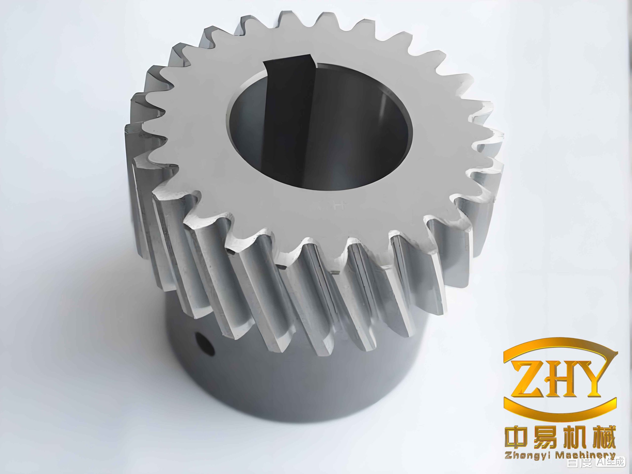
1. Research Context and Motivation. I began from the observation that electric vehicles have advantages such as no direct exhaust emission, fast acceleration, and high energy efficiency. However, the electric drive reducer operates under high speed and high load density. The helical gear pair in the reducer must therefore maintain stable meshing, low vibration, and balanced strength. In conventional design practice, engineers often use trial-and-error and empirical methods. These methods can satisfy the working strength requirement, but they often ignore the unequal strength between the pinion and the gear. If one member of the helical gear pair fails earlier than the other, the whole reducer may fail prematurely. I therefore treated equal strength as a central design criterion for the helical gear pair. At the same time, I considered modification because installation error and tooth deformation can cause edge contact and stress concentration in the helical gear transmission.
2. Helical Gear Tooth Surface Modeling. I established the helical gear tooth surface model by using the rack cutter generation principle. The rack cutter profile is defined in its normal section, and the helical gear tooth surface is obtained by envelope generation. For the pinion and the gear, I used two independent cutter parameters, namely u and l. The position vector of the rack cutter surface in the cutter coordinate system can be written as
$$ \mathbf{R}_{ki}(u_i,l_i)=[u_i,\ l_i,\ 0,\ 1]^T $$
where the subscript i denotes the pinion or the gear. The rack cutter surface is then transformed into the normal section coordinate system by
$$ \mathbf{R}_{ni}(u_i,l_i)=\mathbf{M}_{niki}\mathbf{R}_{ki}(u_i,l_i) $$
The transformation matrix Mniki contains the normal pressure angle and the rack cutter pitch. I expressed it as
$$ \mathbf{M}_{niki}=
\begin{bmatrix}
\cos\alpha_n & \sin\alpha_n & 0 & 0.25s \\
-\sin\alpha_n & \cos\alpha_n & 0 & 0 \\
0 & 0 & 1 & 0 \\
0 & 0 & 0 & 1
\end{bmatrix} $$
The unit normal vector of the rack cutter surface is obtained from the cross product of the two tangent vectors:
$$ \mathbf{N}_{ki}=\frac{\partial \mathbf{R}_{ki}}{\partial u_i}\times \frac{\partial \mathbf{R}_{ki}}{\partial l_i} $$
For a helical gear with addendum modification and high teeth, the generated tooth surface in the gear coordinate system is
$$ \mathbf{R}_i(u_i,l_i,\phi_i)=\mathbf{M}_{iki}\mathbf{R}_{ki}(u_i,l_i) $$
where the transformation chain is
$$ \mathbf{M}_{iki}=\mathbf{M}_{ifi}\mathbf{M}_{fici}\mathbf{M}_{cini}\mathbf{M}_{niki} $$
The individual transformation matrices include the rotation of the gear blank, the rack cutter translation, the helix angle rotation, and the normal section transformation. I used the following forms for the main matrices:
$$ \mathbf{M}_{cini}=
\begin{bmatrix}
1 & 0 & 0 & 0 \\
0 & \cos\beta & -\sin\beta & 0 \\
0 & \sin\beta & \cos\beta & 0 \\
0 & 0 & 0 & 1
\end{bmatrix} $$
$$ \mathbf{M}_{fici}=
\begin{bmatrix}
1 & 0 & 0 & r_i\phi_i \\
0 & 1 & 0 & r_i+x_n m_n \\
0 & 0 & 1 & 0 \\
0 & 0 & 0 & 1
\end{bmatrix} $$
$$ \mathbf{M}_{ifi}=
\begin{bmatrix}
\cos\phi_i & \sin\phi_i & 0 & 0 \\
-\sin\phi_i & \cos\phi_i & 0 & 0 \\
0 & 0 & 1 & 0 \\
0 & 0 & 0 & 1
\end{bmatrix} $$
The meshing equation relates the cutter surface and the generated helical gear tooth surface. I wrote it as
$$ \frac{X_i-x_i}{N_{xi}}=\frac{Y_i-y_i}{N_{yi}} $$
After substituting the transformation matrices, the rotation angle of the gear blank can be solved from
$$ \phi_i=\frac{R_{ciy}(x_n m_n)-R_{cix}N_{ciy}-R_{ciy}N_{cix}}{r_i N_{ciy}} $$
I then transformed the tooth surface into a rotation projection plane to build the full tooth surface mesh. The projection coordinates are defined by
$$ x_{i,kj}^2+y_{i,kj}^2=Y_{kj}^2,\quad z_{i,kj}=X_{kj} $$
where k and j are the mesh indices along the tooth width and tooth height directions. The nonlinear equations were solved numerically so that the pinion and gear tooth surfaces could be represented as discrete point clouds. I used these point clouds for all subsequent tooth contact analysis and modification calculations.
3. Tooth Contact Analysis of the Helical Gear Pair. I constructed a tooth contact analysis model for the helical gear pair by using the continuous tangency condition. For two conjugate tooth surfaces, the position vectors and unit normal vectors must coincide in the fixed frame:
$$ \mathbf{r}_f^{(1)}=\mathbf{r}_f^{(2)},\quad \mathbf{n}_f^{(1)}=\mathbf{n}_f^{(2)} $$
The meshing equation in the fixed frame is
$$ \mathbf{n}_f^{(1)}\cdot \mathbf{v}_f^{(12)}=0 $$
where the relative velocity is
$$ \mathbf{v}_f^{(12)}=\mathbf{n}_f^{(1)}\cdot\left[(\boldsymbol{\omega}^{(1)}-\boldsymbol{\omega}^{(2)})\times \mathbf{r}_f^{(1)}-\mathbf{E}\times \boldsymbol{\omega}^{(2)}\right] $$
I included installation errors in the contact model. The center distance error is ΔE, and the horizontal shaft angle error is θ. The transformation matrix from the gear coordinate system to the fixed frame contains both errors. For the gear, I used
$$ \mathbf{M}_{f2}=\mathbf{M}_{fd}\mathbf{M}_{d2} $$
with
$$ \mathbf{M}_{d2}=
\begin{bmatrix}
\cos\phi_2 & \sin\phi_2\cos\theta & -\sin\phi_2\sin\theta & 0 \\
-\sin\phi_2 & \cos\phi_2\cos\theta & -\cos\phi_2\sin\theta & 0 \\
0 & \sin\theta & \cos\theta & 0 \\
0 & 0 & 0 & 1
\end{bmatrix} $$
$$ \mathbf{M}_{fd}=
\begin{bmatrix}
1 & 0 & 0 & -(E+\Delta E) \\
0 & 1 & 0 & 0 \\
0 & 0 & 1 & 0 \\
0 & 0 & 0 & 1
\end{bmatrix} $$
The equation system contains six unknowns, namely u1, l1, u2, l2, φ1, and φ2. Because the normal vectors have unit length, only five independent algebraic equations are required. I used the pinion rotation angle φ1 as the input parameter and solved the remaining unknowns step by step. The contact points form the contact path on the tooth surface. The geometric transmission error is
$$ GTE=(\phi_2-\phi_{20})-\frac{z_1}{z_2}(\phi_1-\phi_{10}) $$
For edge contact, I used additional boundary conditions. When the pinion tooth flank contacts the gear tooth surface, the pinion parameter l1 is constant, and the contact condition becomes
$$ \mathbf{M}_{f1}\mathbf{R}_1(u_1,l_1(u_1))=\mathbf{M}_{f2}\mathbf{R}_2(u_2,l_2) $$
$$ \frac{\partial \mathbf{R}_1}{\partial u_1}\cdot \mathbf{M}_{f1}\mathbf{n}_f=0 $$
When the pinion tooth tip contacts the gear tooth surface, the pinion parameter u1 is constant, and the condition becomes
$$ \mathbf{M}_{f1}\mathbf{R}_1(u_1(l_1),l_1)=\mathbf{M}_{f2}\mathbf{R}_2(u_2,l_2) $$
$$ \frac{\partial \mathbf{R}_1}{\partial l_1}\cdot \mathbf{M}_{f1}\mathbf{n}_f=0 $$
These equations allow me to detect edge contact caused by center distance error and horizontal shaft angle error. I found that even a small installation error can move the contact path toward the tooth ends or the tooth tip. This effect is important for an electric vehicle helical gear because high speed amplifies the dynamic consequences of edge contact.
4. Principal Curvature and Contact Ellipse. I also computed the principal curvatures and contact ellipse of the helical gear pair. The two tooth surfaces are in line contact in the theoretical case, so a very small modification is required to convert the line contact into point contact for a unique TCA solution. For two surfaces in tangency, the relative principal curvature equations can be written as
$$ \begin{aligned}
b_{11}v_f^{(2)}+b_{12}v_h^{(2)}&=-b_{13} \\
b_{21}v_f^{(2)}+b_{22}v_h^{(2)}&=-b_{23} \\
b_{31}v_f^{(2)}+b_{32}v_h^{(2)}&=-b_{33}
\end{aligned} $$
The coefficients bij depend on the principal curvatures, the angle between the principal directions, the relative angular velocity, and the relative velocity. Once the principal curvatures of the pinion and the gear are known, the contact ellipse semi-axes are
$$ a=\sqrt{\frac{\delta}{A}},\quad b=\sqrt{\frac{\delta}{B}} $$
where δ is the elastic deformation at the contact point. I used δ = 0.00635 mm in my TCA calculations. The coefficients A and B are obtained from
$$ A=\frac{1}{2}\left(K_{\Sigma}^{(1)}-K_{\Sigma}^{(2)}\right)-\frac{1}{2}\sqrt{g_1^2+g_2^2-2g_1g_2\cos2\sigma} $$
$$ B=\frac{1}{2}\left(K_{\Sigma}^{(1)}-K_{\Sigma}^{(2)}\right)+\frac{1}{2}\sqrt{g_1^2+g_2^2-2g_1g_2\cos2\sigma} $$
The contact ellipse orientation is determined by
$$ \tan 2\alpha^{(1)}=\frac{g_2\sin2\sigma}{g_1-g_2\cos2\sigma} $$
I used these relations to visualize the loaded contact pattern and to judge whether the helical gear pair would have a favorable contact path under installation error.
5. Equal-Strength Macro-Geometry Optimization. I treated equal strength as a multi-objective optimization problem. The main failure modes of a helical gear are tooth surface contact fatigue and tooth root bending fatigue. If the pinion and the gear have very different bending strength, one member may fail earlier. I therefore defined the first objective as the maximum contact stress and the second objective as the absolute difference between the pinion and gear root bending stresses. The design variables are the pinion tooth number, normal module, helix angle, and the addendum modification coefficients of the pinion and gear:
$$ \mathbf{X}=[z_1,\ m_n,\ \beta,\ x_{n1},\ x_{n2}]^T $$
The contact stress calculation follows the standard load-capacity method. The contact stress at the pinion and gear is
$$ \sigma_{H1}=Z_B\sigma_{H0}\sqrt{K_A K_V K_{H\beta}K_{H\alpha}} $$
$$ \sigma_{H2}=Z_D\sigma_{H0}\sqrt{K_A K_V K_{H\beta}K_{H\alpha}} $$
The basic contact stress at the pitch point is
$$ \sigma_{H0}=Z_H Z_E Z_\epsilon Z_\beta \sqrt{\frac{F_t}{d_1 b}\frac{u+1}{u}} $$
The root bending stress is
$$ \sigma_{F1}=\sigma_{F01}K_A K_V K_{F\beta}K_{F\alpha} $$
$$ \sigma_{F2}=\sigma_{F02}K_A K_V K_{F\beta}K_{F\alpha} $$
The basic root bending stress is
$$ \sigma_{F0}=\frac{F_t}{b m_n}Y_F Y_S Y_\beta $$
I therefore formulated the optimization objectives as
$$ \min f_1=\sigma_H $$
$$ \min f_2=\left|\sigma_{F1}-\sigma_{F2}\right| $$
The constraints include contact strength, bending strength, center distance, total contact ratio, tooth tip thickness, and undercut prevention. These constraints are summarized in the following table.
| Constraint | Expression | Purpose |
|---|---|---|
| Contact strength of pinion | \(\sigma_{H1}\le [\sigma_{HP}]_1\) | Avoid pitting on the helical gear tooth surface |
| Contact strength of gear | \(\sigma_{H2}\le [\sigma_{HP}]_2\) | Ensure surface durability of the helical gear |
| Bending strength of pinion | \(\sigma_{F1}\le [\sigma_{FP}]_1\) | Prevent pinion root fracture |
| Bending strength of gear | \(\sigma_{F2}\le [\sigma_{FP}]_2\) | Prevent gear root fracture |
| Center distance | \(|a’-a|\le 0.01\ \text{mm}\) | Maintain the designed housing distance |
| Total contact ratio | \(\epsilon_\gamma\ge 2\) | Ensure smooth helical gear meshing |
| Tooth tip thickness | \(S_a\ge 0.4m_n\) | Prevent tip breakage |
| Undercut prevention | \(x_n\ge \frac{h_a^*z\sin^2\alpha_t}{2\cos\beta}\) | Ensure proper generation of the helical gear |
I solved this multi-objective optimization problem with a multi-objective particle swarm optimization algorithm. The velocity and position of each particle are updated by
$$ V_i^{t+1}=wV_i^t+c_1r_1(p_{best,i}-X_i^t)+c_2r_2(g_{best}-X_i^t) $$
$$ X_i^{t+1}=X_i^t+V_i^{t+1} $$
The Pareto dominance relation is defined as
$$ \forall k\in\{1,\dots,n\},\ f_k(x_a)\le f_k(x_b)\quad \text{and}\quad \exists l,\ f_l(x_a)<f_l(x_b) $$=""
I also introduced a mutation strategy to avoid premature convergence. The mutation was applied to part of the swarm, and the mutation probability decreased with the generation number. The main algorithm settings are listed below.
| Parameter | Value |
|---|---|
| Population size | 200 |
| External archive size | 40 |
| Inertia factor | 0.8 |
| Individual learning factor | 2.0 |
| Global learning factor | 2.0 |
| Mutation probability | 0.45 |
| Maximum iterations | 1000 |
I applied this equal-strength optimization to a two-stage reducer of an electric vehicle. The original macro-geometry of the first-stage helical gear pair and the second-stage helical gear pair is given in the following table.
| Parameter | First-stage helical gear pair | Second-stage helical gear pair |
|---|---|---|
| Pinion tooth number, \(z_1\) | 19 | 27 |
| Gear tooth number, \(z_2\) | 59 | 87 |
| Normal module, \(m_n\) (mm) | 2.5 | 2 |
| Normal pressure angle, \(\alpha_n\) (deg) | 20 | 20 |
| Helix angle, \(\beta\) (deg) | 15.3 | 18.1 |
| Pinion face width, \(b_1\) (mm) | 30 | 33 |
| Gear face width, \(b_2\) (mm) | 30 | 33 |
| Addendum coefficient, \(h_{an}^*\) | 1.25 | 1.20 |
| Bottom clearance coefficient, \(c_n^*\) | 0.25 | 0.25 |
| Root fillet radius, \(\rho_f\) (mm) | 0.75 | 0.60 |
| Pinion modification coefficient, \(x_{n1}\) | 0.101 | 0.153 |
| Gear modification coefficient, \(x_{n2}\) | -0.134 | -0.120 |
The initial static strength results showed that the contact stress was high and that the bending stress difference between the pinion and the gear was noticeable. This confirmed the need for equal-strength optimization.
| Quantity | First-stage helical gear pair | Second-stage helical gear pair |
|---|---|---|
| Contact stress \(\sigma_H\) (MPa) | 1005.441 | 1098.850 |
| Pinion root bending stress \(\sigma_{F1}\) (MPa) | 197.653 | 213.540 |
| Gear root bending stress \(\sigma_{F2}\) (MPa) | 146.930 | 186.590 |
| Bending stress difference (MPa) | 50.723 | 26.950 |
After optimization, I obtained a Pareto front. Because the two objectives conflict, no single solution is best for both objectives. I selected three representative solutions, A, B, and C. Solution A mainly reduces the bending stress difference. Solution C mainly reduces the contact stress. Solution B gives a balanced compromise. I selected solution B for the subsequent modification study. The optimization results are shown below.
| Variable | Original | Solution A | Solution B | Solution C |
|---|---|---|---|---|
| Pinion tooth number, \(z_1\) | 19 | 25 | 21 | 23 |
| Gear tooth number, \(z_2\) | 59 | 73 | 57 | 54 |
| Normal module, \(m_n\) (mm) | 2.5 | 2.0 | 2.5 | 2.5 |
| Helix angle, \(\beta\) (deg) | 15.3 | 13.8 | 14.8 | 17.5 |
| Pinion modification, \(x_{n1}\) | 0.101 | 0.154 | 0.213 | 0.157 |
| Gear modification, \(x_{n2}\) | -0.134 | -0.110 | -0.151 | -0.125 |
| Contact stress \(\sigma_H\) (MPa) | 1005.441 | 989.960 | 951.850 | 917.540 |
| Pinion root bending stress \(\sigma_{F1}\) (MPa) | 197.653 | 186.546 | 152.857 | 163.890 |
| Gear root bending stress \(\sigma_{F2}\) (MPa) | 146.930 | 185.766 | 141.182 | 140.994 |
| Bending stress difference (MPa) | 50.723 | 0.780 | 11.675 | 22.896 |
Compared with the original design, solution B reduced the maximum contact stress by 53.591 MPa and reduced the maximum bending stress difference by 39.048 MPa. This means that the helical gear pair became more balanced in strength while the tooth surface contact condition also improved. I used solution B as the base macro-geometry for the modification design.
6. Tooth Surface Modification Design. I developed a unified modification method that includes profile modification, lead modification, and topological modification. The pinion is more suitable for modification than the gear because it has fewer teeth and can be manufactured more efficiently. I designed the modification curve in both the profile direction and the lead direction as a three-segment curve composed of one straight segment and two parabolic segments. The lead modification curve is
$$ \delta_b(l)=
\begin{cases}
l_5\left(\dfrac{l-\frac{b}{2}+l_6}{l_6}\right)^k, & -\dfrac{b}{2}\le l\le -\dfrac{b}{2}+l_6 \\[6pt]
0, & -\dfrac{b}{2}+l_6<l<\dfrac{b}{2}-l_8 $$="" &=""
The profile modification curve is
$$ \delta_q(h)=
\begin{cases}
l_1\left(\dfrac{h-r_h+l_2}{l_2}\right)^k, & r_h-l_2\le h\le r_h \\[6pt]
0, & r_h<h<r_a-l_4 $$="" &=""
I used k = 2 for the parabolic exponent. The modified pinion tooth surface is obtained by superimposing the modification amount on the theoretical tooth surface:
$$ \mathbf{R}_1^*(u_1,l_1)=\mathbf{R}_1(u_1,l_1)+\delta(h,l)\mathbf{n}_1(u_1,l_1) $$
where
$$ \delta(h,l)=\delta_q(h)+\delta_b(l) $$
The normal vector of the modified tooth surface is
$$ \mathbf{n}_1^*=
\frac{\partial \mathbf{R}_1^*}{\partial u_1}\times
\frac{\partial \mathbf{R}_1^*}{\partial l_1} $$
I then replaced the theoretical pinion tooth surface with the modified pinion tooth surface in the TCA model and included edge contact. This allowed me to study how profile modification, lead modification, and topological modification affect the geometric contact behavior of the helical gear pair.
7. Effect of Different Modification Types. I first studied profile modification. I used three groups of profile modification parameters. I found that profile modification often causes edge contact at the two ends of the tooth width. A large root relief shifts the contact points toward the tooth tip, while a large tip relief shifts the contact points toward the tooth root. Both cases can cause impact at the engaging-in or engaging-out position. I also found that the geometric transmission error curve becomes asymmetric when the modification is not balanced.
I then studied lead modification. I used three groups of lead modification parameters. I found that lead modification tends to produce edge contact at the tooth tip and tooth root. The contact points outside the edge contact region concentrate in the transition zone between the modified and unmodified regions. The contact path becomes nearly perpendicular to the lead direction. The geometric transmission error curve shows large fluctuations near the tooth tip and tooth root, which is unfavorable for a high-speed helical gear transmission.
Finally, I studied topological modification. I combined the third profile modification group and the third lead modification group. The topological modification reduced the edge contact compared with a single profile modification or a single lead modification. However, slight edge contact still appeared near the engaging-in and engaging-out positions. I therefore optimized the topological modification parameters to further suppress edge contact and improve the geometric transmission error.
| Modification type | Main effect on helical gear contact | Risk |
|---|---|---|
| Profile modification | Changes contact position along tooth height | Edge contact at tooth width ends |
| Lead modification | Changes contact position along tooth width | Edge contact at tooth tip and root |
| Topological modification | Combines profile and lead effects | Needs parameter optimization to avoid residual edge contact |
8. Optimization of Topological Modification. I considered the case in which the helical gear pair has a center distance error of 0.02 mm and a horizontal shaft angle error of 0.2 arcmin. I used the eight modification parameters l1 to l8 as design variables. The first objective was to place the middle contact point as close as possible to the center of the working tooth surface. The second objective was to make the geometric transmission error amplitude at the two ends of the contact path equal. The optimization problem is
$$ \min f_1=\sqrt{(x_B-x_A)^2+(y_B-y_A)^2} $$
$$ \min f_2=\left|\Delta\phi_{x1}-\Delta\phi_{x2}\right| $$
The constraints ensure that the engaging-in point and the engaging-out point do not lie on the tooth boundary. I also constrained the modification amounts and modification lengths within practical ranges. I used a multi-objective particle swarm optimization algorithm again. The final selected solution had
$$ f_1=1.396\ \text{mm},\quad f_2=3.207” $$
The corresponding topological modification parameters are listed below.
| Parameter | Value | Parameter | Value |
|---|---|---|---|
| Root relief amount, \(l_1\) | 5.3 μm | Left-end relief amount, \(l_5\) | 3.98 μm |
| Root relief length, \(l_2\) | 2.15 mm | Left-end relief length, \(l_6\) | 13.56 mm |
| Tip relief amount, \(l_3\) | 7.195 μm | Right-end relief amount, \(l_7\) | 4.31 μm |
| Tip relief length, \(l_4\) | 2.15 mm | Right-end relief length, \(l_8\) | 14.88 mm |
The modified pinion tooth surface was superimposed on the theoretical tooth surface, and the TCA algorithm with edge contact was run again. After optimization, the helical gear pair had no edge contact at the two tooth width ends or at the tooth tip. The contact path became close to a straight line. This reduced the sensitivity of the contact pattern to installation error. The geometric transmission error curve became nearly symmetric at its two ends, which lowered the probability of edge contact under light load. This result shows that topological modification is an effective way to improve the meshing quality of a high-speed electric vehicle helical gear pair.
9. Validation with Transmission Simulation Software. I verified the equal-strength design and the topological modification by using a professional transmission simulation software. I built three-dimensional models of the helical gear pair before and after equal-strength optimization. I applied a torque of 140 N·m to the pinion and constrained the radial and axial displacements, leaving only the axial rotation free. I used a friction coefficient of 0.1 and refined the mesh near the tooth surface and root. The simulation results are compared with my theoretical results in the following table.
| Quantity | Theoretical result | Simulation result | Difference |
|---|---|---|---|
| Contact stress before optimization (MPa) | 1005.441 | 952.151 | 5.30% |
| Pinion root bending stress before optimization (MPa) | 197.653 | 172.942 | 12.50% |
| Gear root bending stress before optimization (MPa) | 146.930 | 139.535 | 5.03% |
| Contact stress after optimization (MPa) | 951.850 | 892.570 | 6.23% |
| Pinion root bending stress after optimization (MPa) | 152.857 | 139.923 | 8.46% |
| Gear root bending stress after optimization (MPa) | 141.182 | 122.542 | 13.20% |
The simulated contact stress before and after optimization was 952.151 MPa and 892.570 MPa, respectively. The differences from my theoretical values were 5.30% and 6.23%. The simulated bending stress difference before optimization was 33.407 MPa, which was smaller than the theoretical value by 17.316 MPa. The simulated bending stress difference after optimization was 17.380 MPa, which was larger than the theoretical value by 5.705 MPa. These differences are acceptable for engineering design. I therefore concluded that the equal-strength optimization is feasible for the helical gear transmission.
I also compared the contact pattern and geometric transmission error under installation error. When only center distance error exists, the contact pattern moves toward the two tooth width ends, but the transmission ratio remains almost unchanged. When only horizontal shaft angle error exists, the contact pattern moves toward one end of the tooth width, and the geometric transmission error amplitude increases. When both errors exist, the unmodified helical gear pair shows clear edge contact. After topological modification, the contact pattern returns to the middle of the tooth surface and the edge contact disappears. The simulation results agree with my TCA results. This validation confirms that the proposed modification method can improve the geometric contact behavior of the helical gear pair.
| Error case | Unmodified helical gear contact | Topologically modified helical gear contact |
|---|---|---|
| Center distance error only | Edge contact at both tooth width ends | Contact path moves toward the middle |
| Horizontal shaft angle error only | Severe edge contact at one tooth width end | Contact path becomes nearly straight |
| Both errors | Combined edge contact and large transmission error | No edge contact and reduced transmission error |
10. Discussion. My study shows that the design of a helical gear for an electric vehicle should not be separated into macro-geometry design and micro-modification design. The two parts interact strongly. The equal-strength macro-geometry changes the tooth number, module, helix angle, and modification coefficients; these changes alter the contact stress, root bending stress, contact ratio, and contact path. The subsequent topological modification then compensates for installation error and elastic deformation. If the macro-geometry is not balanced, the modification may need a larger relief amount, which can reduce the effective contact area and increase the risk of edge contact. If the modification is not optimized, the equal-strength design may still produce a poor contact pattern under installation error. Therefore, I treated the helical gear design as an integrated process.
The most important finding for the helical gear is that a straight contact path is desirable under installation error. A straight contact path keeps the loaded region away from the tooth edges and reduces the sensitivity of the helical gear pair to center distance error and shaft angle error. A symmetric geometric transmission error curve is also desirable because it reduces the impact at engaging-in and engaging-out positions. In my optimized design, the contact path became close to a straight line, and the two ends of the geometric transmission error curve became nearly equal. This is beneficial for reducing vibration and noise in a high-speed electric vehicle reducer.
I also found that the equal-strength objective improves the balance between the pinion and the gear. In a conventional design, the pinion often has a higher root bending stress than the gear because it has fewer teeth and a smaller tooth thickness. If the difference is too large, the pinion may fail first, and the gear may still have remaining life. This is not an efficient use of material. By reducing the bending stress difference, I made the two members of the helical gear pair more consistent in life expectancy. At the same time, I reduced the maximum contact stress, which improves the surface durability of the helical gear.
11. Practical Implications. The method I developed can be used in the early design stage of an electric vehicle reducer. It requires the basic gear parameters, the load spectrum, the material properties, and the expected installation error. The output includes the equal-strength macro-geometry and the optimized topological modification parameters. The designer can then use the TCA model to check the contact path and geometric transmission error before manufacturing. This reduces the need for repeated trial cuts and滚检? Wait, need English. I must remove any Chinese. “trial cuts and rolling tests”. Let me correct: This reduces the need for repeated trial cuts and rolling tests. The simulation software can further verify the design under load. Because the method is based on standard gear geometry and load-capacity formulas, it can be adapted to different electric vehicle reducers by changing the input parameters.
For the helical gear pair, the following design rules emerged from my work:
| Design rule | Reason |
|---|---|
| Use equal-strength objectives for the pinion and the gear | Reduce the risk of premature failure of one member |
| Control the contact stress as a primary surface objective | Improve pitting resistance of the helical gear |
| Avoid edge contact under installation error | Prevent stress concentration and impact |
| Keep the contact path near the middle of the tooth width | Increase effective contact area and load capacity |
| Make the geometric transmission error curve symmetric | Reduce vibration and noise at engaging-in and engaging-out |
| Prefer topological modification for the pinion | Compensate both profile and lead deviations |
12. Conclusions. I established a tooth surface design method for electric vehicle helical gear transmissions based on equal strength and modification. My main conclusions are as follows. First, I built a full tooth surface model of a modified high-tooth helical gear by using the rack cutter generation principle. The model includes the cutter geometry, coordinate transformations, meshing equation, and discrete tooth surface mesh. Second, I built a TCA model with installation error and edge contact. I found that center distance error and horizontal shaft angle error can move the contact path toward the tooth boundary and cause edge contact. Third, I formulated an equal-strength multi-objective optimization problem for the helical gear pair. The design variables were tooth number, normal module, helix angle, and modification coefficients. The objectives were minimum contact stress and minimum root bending stress difference. The optimized solution reduced both the contact stress and the bending stress difference. Fourth, I developed a unified modification method including profile modification, lead modification, and topological modification. I found that profile modification tends to cause edge contact at the tooth width ends, lead modification tends to cause edge contact at the tooth tip and root, and topological modification can reduce edge contact when its parameters are optimized. Fifth, I optimized the topological modification parameters for a helical gear pair with both center distance error and horizontal shaft angle error. The optimized contact path became close to a straight line, and the geometric transmission error curve became nearly symmetric. Sixth, I validated the equal-strength design and the topological modification with a transmission simulation software. The simulation results agreed with my theoretical results within engineering accuracy.
13. Future Work. I see several directions for further study. I only used a second-order modification curve in this work. Higher-order modification curves may provide more freedom to control the contact path and transmission error of the helical gear. I also performed the contact analysis mainly under light load. In a real electric vehicle reducer, the helical gear operates under a wide range of torque and speed. A loaded tooth contact analysis and dynamic analysis under the actual load spectrum would be valuable. In addition, I used simulation software for validation. Future work should include bench tests of the helical gear pair to verify the contact pattern, transmission error, vibration, and noise. Finally, the equal-strength design could be extended to the whole reducer, including bearings and shafts, so that the entire electric vehicle transmission system is balanced rather than only the helical gear pair.
In summary, I believe that the combination of equal-strength macro-geometry optimization and topological modification is a practical and effective approach for the tooth surface design of electric vehicle helical gear transmissions. It improves the balance between the pinion and the gear, reduces edge contact, lowers the sensitivity to installation error, and supports the development of high-speed, low-noise, and long-life electric vehicle reducers.
</h</l