
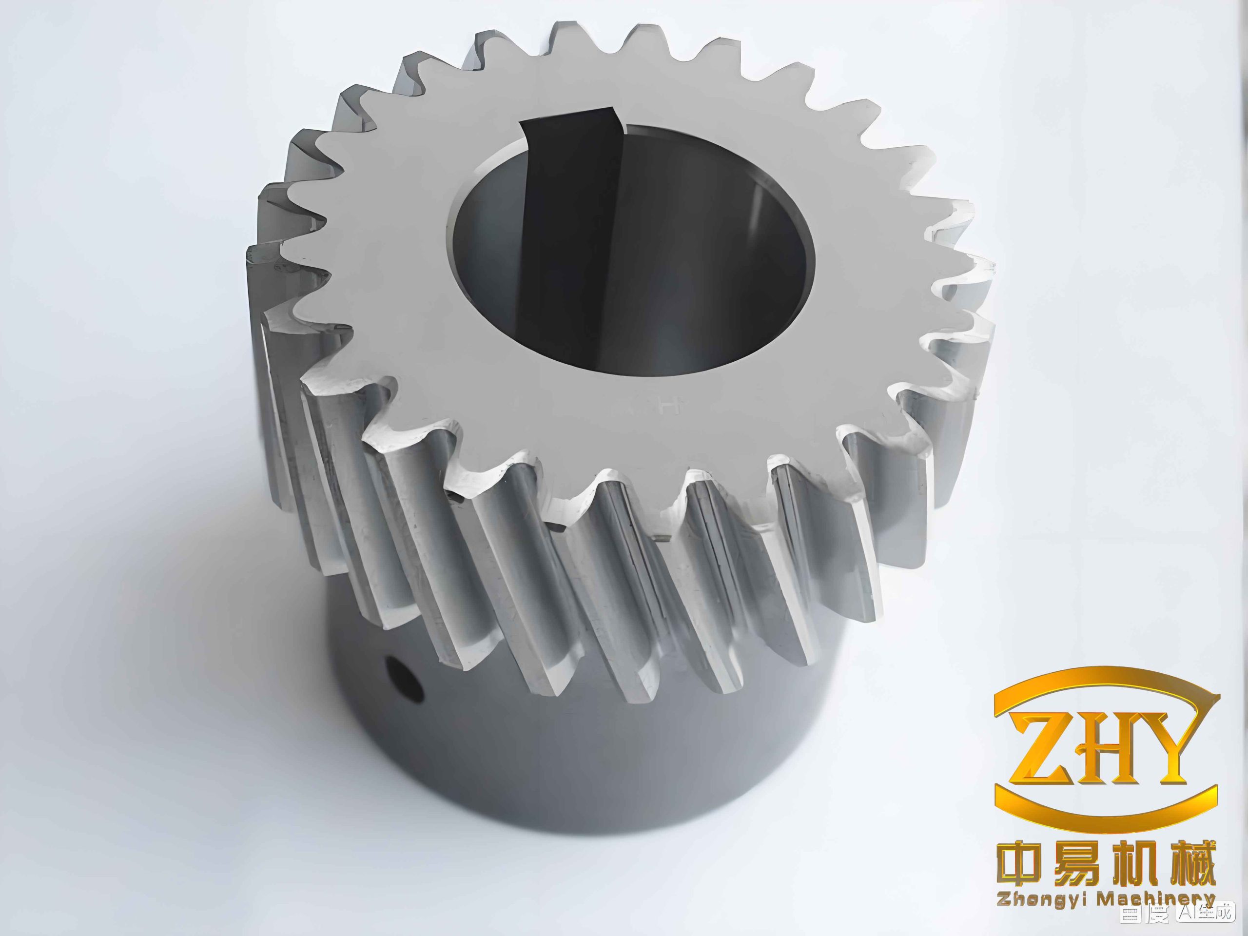
I study the problem of tooth-surface distortion that appears when worm grinding wheels are used to grind cylindrical helical gears with lead modification. In my view, this problem is central to high-precision gear manufacturing because helical gears are widely used in electric vehicles, aerospace systems, energy equipment, marine transmissions, and many other mechanical systems. A helical gear transmission can provide high load capacity, smooth motion, low noise, and long service life, but these advantages depend strongly on the accuracy of the tooth flanks. When a worm grinding wheel generates a lead-modified helical gear, the left and right flanks do not experience the same instantaneous contact condition along the tooth width. As a result, the pressure angle at a given transverse section changes from one tooth-width position to another. This change is what I call tooth-surface distortion. It increases vibration, reduces transmission accuracy, and raises noise. Therefore, I developed a dressing method in which the worm grinding wheel is intentionally formed with an arc-shaped profile so that the natural distortion of helical gears can be compensated during generating grinding.
I begin from the generating grinding principle. Worm grinding of helical gears can be treated as the meshing of a pair of crossed-axis involute helical gears. The worm grinding wheel rotates about its own axis and simultaneously moves along the gear axis. At the same time, the wheel may be shifted along its own axis to bring new abrasive grains into contact with the workpiece. The gear rotates in a timed relationship with the wheel. Because the worm has a small number of starts and the gear has many teeth, the contact point sweeps across the tooth surface and envelopes the complete flank. The motions are coupled through the machine axes. I summarize the main axis functions in the following table.
| Machine motion | Function in worm grinding of helical gears |
|---|---|
| Radial feed | Controls the center distance between the worm grinding wheel and the helical gear, and therefore controls the stock removal and lead modification amount. |
| Axial shift of the wheel | Moves the worm grinding wheel along its own axis so that new abrasive grains enter the grinding zone. |
| Axial stroke along the gear | Moves the wheel along the gear axis to generate the full tooth width of the helical gears. |
| Wheel swivel | Aligns the worm grinding wheel with the helix angle of the helical gears and the lead angle of the wheel. |
| Wheel rotation | Provides the main grinding motion and establishes the generating motion with the workpiece. |
| Workpiece rotation | Generates the involute flank of the helical gears in synchronism with the wheel rotation. |
| Dressing roller rotation | Forms the worm grinding wheel profile and generates the arc-shaped dressing required for anti-distortion compensation. |
| Dressing roller swivel | Sets the dressing roller orientation relative to the worm grinding wheel during profile dressing. |
I describe the timed relationship between the worm grinding wheel and the helical gear by using the transmission ratio. If the worm has n starts and the helical gear has z teeth, then the nominal ratio is
$$ i_{21}=\frac{\omega_2}{\omega_1}=\frac{n}{z}. $$
The lead parameters of the worm grinding wheel and the helical gear are also needed. I write them as
$$ P_1=\frac{m_n n}{2\cos\lambda}, $$
$$ P_2=\frac{m_n z}{2\sin\beta}. $$
Here, m_n is the normal module, lambda is the lead angle of the worm grinding wheel, and beta is the helix angle of the helical gears. The shaft angle between the worm grinding wheel and the helical gear is
$$ \Sigma=\frac{\pi}{2}\pm\beta\pm\lambda. $$
The signs depend on the hand of the helical gears and the hand of the worm grinding wheel. I use this relationship to establish the crossed-axis meshing coordinate system. The coordinate transformation from the worm wheel system to the gear system is the foundation of the envelope calculation. I define the transformation matrix as
$$ \mathbf{r}_2(u,\theta,\phi_1,\phi_2)=\mathbf{M}_{2p}(\phi_2)\mathbf{M}_{p0}\mathbf{M}_{01}(\phi_1)\mathbf{r}_1(u,\theta). $$
For the numerical work, I use the following matrix forms:
$$ \mathbf{M}_{01}(\phi_1)=
\begin{bmatrix}
\cos\phi_1 & -\sin\phi_1 & 0 & 0\\
\sin\phi_1 & \cos\phi_1 & 0 & 0\\
0 & 0 & 1 & l_1\\
0 & 0 & 0 & 1
\end{bmatrix}, $$
$$ \mathbf{M}_{p0}=
\begin{bmatrix}
1 & 0 & 0 & a\\
0 & \cos\Sigma & -\sin\Sigma & 0\\
0 & \sin\Sigma & \cos\Sigma & 0\\
0 & 0 & 0 & 1
\end{bmatrix}, $$
$$ \mathbf{M}_{2p}(\phi_2)=
\begin{bmatrix}
\cos\phi_2 & \sin\phi_2 & 0 & 0\\
-\sin\phi_2 & \cos\phi_2 & 0 & 0\\
0 & 0 & 1 & -l_2\\
0 & 0 & 0 & 1
\end{bmatrix}. $$
In these expressions, a is the center distance between the worm grinding wheel and the helical gear, while l1 and l2 are the axial displacements of the wheel and the gear. The worm grinding wheel surface can be represented as an involute helicoid. I use the parameterization
$$ x_1=r_b[\cos(\theta+u)+u\sin(\theta+u)], $$
$$ y_1=r_b[\sin(\theta+u)-u\cos(\theta+u)], $$
$$ z_1=P_1\theta. $$
Here, r_b is the base radius, u is the involute roll parameter, and theta is the helix parameter. The meshing condition between the worm grinding wheel and the helical gears is obtained from the relative velocity and the common normal. I write it as
$$ \mathbf{v}^{(12)}\cdot\mathbf{n}=0. $$
The relative velocity is
$$ \mathbf{v}^{(12)}=\mathbf{v}^{(1)}-\mathbf{v}^{(2)}, $$
where the velocity of a point on the worm grinding wheel is
$$ \mathbf{v}^{(1)}=\boldsymbol{\omega}_1\times\mathbf{r}+\mathbf{v}_{01}, $$
and the velocity of the same point regarded as part of the helical gear is
$$ \mathbf{v}^{(2)}=\boldsymbol{\omega}_2\times\mathbf{r}_p+\mathbf{v}_{02}. $$
After substituting the coordinate transformations, the meshing equation becomes a nonlinear relation among the surface parameters and the rotation angles. I solve it by enforcing two independent conditions that arise from the two-parameter envelope. For a fixed generating position, only one combination of u and theta satisfies both conditions. By sweeping a series of points from the tooth tip to the tooth root on the transverse profile, I obtain a family of instantaneous contact lines. These contact lines are the traces along which the worm grinding wheel removes material from the helical gears.
For lead modification, I use a crowning model because crowning is a common and effective way to avoid edge contact in helical gears. The crowning curve changes the center distance as the worm grinding wheel travels along the gear axis. Therefore, the modification amount is a function of the tooth-width coordinate. I write the modification curve as
$$ f(z)=\frac{C_r}{0.4b^2}z^2, $$
where C_r is the total crowning amount and b is the face width. I define the measured tooth-width positions as
$$ z_k^d\in[-0.4b,0.4b],\qquad k=1,2,\dots,n. $$
At each tooth-width position, the center distance is changed by the local modification amount. The meshing equation then becomes dependent on the crowning function. I write the modified meshing condition as
$$ \mathbf{v}^{(12)}(f(z_k))\cdot\mathbf{n}=0. $$
I solve this equation by an iterative procedure. For each transverse section of the helical gears, I compute the contact point from the tip to the root. The resulting instantaneous contact lines are not straight lines in the transverse plane. They are inclined and asymmetric between the left and right flanks. This asymmetry is the geometric origin of tooth-surface distortion in helical gears.
I selected a representative set of gear parameters to explain the calculation. The basic data are listed below.
| Parameter | Value |
|---|---|
| Number of teeth z | 50 |
| Normal module m_n | 3 mm |
| Normal pressure angle alpha_n | 20 degrees |
| Transverse pressure angle alpha_t | 22.8 degrees |
| Involute length L_ea | 17.98 mm |
| Helix angle beta | 30 degrees |
| Face width b | 30 mm |
| Crowning amount C_r | 27.5 micrometers |
Using these data, I compute the contact lines for the left and right flanks. I find that the contact line length along the tooth width is controlled by the base helix angle and the normal module. The axial distance from the start of the contact line to the pitch line is
$$ L_f=\left(\sqrt{r^2-r_b^2}-\sqrt{r_f^2-r_b^2}\right)\tan\beta_b, $$
and the axial distance from the pitch line to the end of the contact line is
$$ L_a=\left(\sqrt{r_a^2-r_b^2}-\sqrt{r^2-r_b^2}\right)\tan\beta_b. $$
In these equations, r is the pitch radius, r_b is the base radius, r_f is the start radius of the active involute, and r_a is the tip radius of the helical gears. The start radius of the active involute is not exactly the root radius because a root relief or undercut may be present. I approximate it as
$$ r_f=r_a-h_a^*m_n, $$
where h_a^* is the addendum coefficient. I observe that larger normal module and larger base helix angle both increase L_f and L_a. This means that the contact line becomes longer along the tooth width, and the distortion of the helical gears becomes more severe.
To quantify the distortion, I introduce the height difference between the actual modification curve and the theoretical modification curve. The height difference is
$$ S_v=\frac{\pi m_n\sin\beta_b}{4}. $$
The base helix angle is related to the helix angle and the pressure angles by
$$ \cos\beta_b=\frac{\cos\beta\cos\alpha_n}{\cos\alpha_t}. $$
I use this relation to evaluate how the helical gears behave for different parameter combinations. The height difference increases with the normal module and the base helix angle. In other words, helical gears with large helix angles and large modules are more likely to suffer from strong tooth-surface distortion. This is one reason why distortion control is so important for modern helical gears in high-speed and high-load applications.
I then derive the local tooth profile deviation caused by distortion. At a given tooth-width position k, I denote the modification amount at the pitch point as f(z_k). The actual modification amount on the left or right flank is shifted by the height difference. I write the local modification for the left and right flanks as
$$ f_L(z_k)=f(z_k)-S_v, $$
$$ f_R(z_k)=f(z_k)+S_v. $$
For each tooth-width position, I sample the profile from the tip to the root. The profile deviation at position k is the difference between the modification at the last sampled point and the first sampled point:
$$ f_{H\alpha k}=f(z_k^m)-f(z_k^1). $$
The corresponding pressure angle deviation is
$$ \Delta\alpha_k=-\frac{f_{H\alpha k}}{L_{ea}\tan\alpha_t}. $$
I find that the left and right flanks usually have opposite signs of pressure angle deviation at the same transverse section. For a right-handed helical gear, the right flank may show a negative profile deviation near one end and a positive profile deviation near the other end. The left flank shows the opposite trend. This opposite behavior is the signature of distortion. It cannot be removed by simply changing the crowning amount, because the crowning amount is symmetric while the distortion is antisymmetric.
I evaluated the influence of the crowning amount and helix angle on the profile deviation. For a fixed measurement position near the top of the tooth width, increasing either the crowning amount or the helix angle increases the absolute profile deviation. The same conclusion holds near the bottom of the tooth width, but the sign is reversed. Therefore, the distortion amount grows with both the lead modification amount and the helix angle. This agrees with my contact line analysis. The distortion is a natural consequence of the spatial contact line orientation in helical gears.
To compensate the distortion, I propose an arc-shaped worm grinding wheel. The idea is to make the worm grinding wheel profile curved along its axis so that different tooth-width positions of the helical gears are ground by different effective pressure angles. By matching the curvature of the worm grinding wheel to the pressure angle deviation of the helical gears, I can cancel the natural distortion. The arc-shaped worm grinding wheel is produced by a diamond dressing roller. The dressing roller follows a spline path that combines the normal profile dressing motion with an additional radial offset. This additional offset changes the effective pressure angle along the wheel axis.
The anti-distortion principle can be stated simply. For each measured tooth-width position, I calculate the pressure angle deviation of the helical gears. This pressure angle deviation determines the amount of material that must be removed or left on the flank. I then convert this required pressure angle change into a dressing radius for the worm grinding wheel. The arc-shaped wheel then grinds the helical gears with a pressure angle that varies along the tooth width. In this way, the natural distortion is superimposed with an equal and opposite distortion from the dressing, and the final tooth surface is nearly free of distortion.
I define the compensation length along the worm grinding wheel as
$$ \Delta W_k=\frac{W\Delta Z_k}{B}, $$
where W is the total usable compensation length on the worm grinding wheel, B is the measurement face width of the helical gears, and Delta Z_k is the position of the measured section. The relation between the compensation length and the pressure angle deviation is
$$ \Delta W_k=(R_k-r)\cos(\Delta\alpha_k)\cos\lambda. $$
Combining these equations gives the required arc radius in the normal plane of the helical gears:
$$ R_k=r+\frac{W\Delta Z_k}{B\cos(\Delta\alpha_k)\cos\lambda}. $$
For dressing, I project this radius onto the axial plane of the worm grinding wheel. I write the projected radius as
$$ R’_k=\frac{R_kR_w\cos\lambda}{R_w+R_k\cos(90^\circ-\lambda)}, $$
where R_w is the nominal radius of the worm grinding wheel. I use this projected radius to generate the dressing path. The diamond roller then moves along the worm axis while the radial offset changes according to the spline points. The result is an arc-shaped worm grinding wheel that has a continuous pressure angle variation along its usable length.
I calculated the dressing data for a representative case. The left-flank dressing data are listed below.
| Tooth-width position Delta Z_k (mm) | Distortion f_H_alpha_k (micrometers) | Pressure angle deviation Delta alpha_k | Wheel compensation length Delta W_k (mm) | Arc radius R_k (mm) |
|---|---|---|---|---|
| 12 | 47.5 | -0.00628 | 30 | 4386.8 |
| 10 | 40.2 | -0.00532 | 25 | 4322.9 |
| 8 | 32.9 | -0.00435 | 20 | 4230.6 |
| 6 | 25.6 | -0.00338 | 15 | 4085.3 |
| 4 | 18.2 | -0.00242 | 10 | 3823.4 |
| 2 | 10.9 | -0.00145 | 5 | 3209.7 |
| 0 | 3.6 | -0.00048 | 0 | 86.4948 |
| -2 | -3.7 | 0.00049 | -5 | 9190.4 |
| -4 | -11.0 | 0.00145 | -10 | 6243.0 |
| -6 | -18.3 | 0.00242 | -15 | 5643.4 |
| -8 | -25.6 | 0.00338 | -20 | 5385.3 |
| -10 | -32.9 | 0.00435 | -25 | 5241.7 |
| -12 | -40.2 | 0.00532 | -30 | 5150.2 |
The right-flank dressing data are listed below.
| Tooth-width position Delta Z_k (mm) | Distortion f_H_alpha_k (micrometers) | Pressure angle deviation Delta alpha_k | Wheel compensation length Delta W_k (mm) | Arc radius R_k (mm) |
|---|---|---|---|---|
| 12 | -40.2 | 0.00532 | 30 | 5150.2 |
| 10 | -32.9 | 0.00435 | 25 | 5241.7 |
| 8 | -25.6 | 0.00338 | 20 | 5385.3 |
| 6 | -18.3 | 0.00242 | 15 | 5643.4 |
| 4 | -11.0 | 0.00145 | 10 | 6243.0 |
| 2 | -3.7 | 0.00049 | 5 | 9190.4 |
| 0 | 3.6 | -0.00048 | 0 | 86.4948 |
| -2 | 10.9 | -0.00145 | -5 | 3209.7 |
| -4 | 18.2 | -0.00242 | -10 | 3823.4 |
| -6 | 25.6 | -0.00338 | -15 | 4085.3 |
| -8 | 32.9 | -0.00435 | -20 | 4230.6 |
| -10 | 40.2 | -0.00532 | -25 | 4322.9 |
| -12 | 47.5 | -0.00628 | -30 | 4386.8 |
I simulated the grinding process with these dressing data. The compensation results for the tooth tip and tooth root are shown in the next table.
| Flank | Tip lead deviation before compensation (micrometers) | Tip lead deviation after compensation (micrometers) | Root lead deviation before compensation (micrometers) | Root lead deviation after compensation (micrometers) |
|---|---|---|---|---|
| Left flank | 34.7 | -32.8 | -52.9 | 51.1 |
| Right flank | -34.7 | 32.8 | 52.9 | -51.1 |
After compensation, the tip lead deviation of the left flank is reduced from 34.7 micrometers to about 1.9 micrometers, a reduction of 94.5 percent. The root lead deviation is reduced from -52.9 micrometers to about -1.8 micrometers, a reduction of 96.6 percent. The right flank shows the same magnitude of improvement with opposite signs. I also checked the profile deviation at a measured tooth-width position of 12 mm. The left flank profile deviation is reduced from 47.5 micrometers to 2.3 micrometers, a reduction of 95.2 percent. The right flank profile deviation is reduced from -40.2 micrometers to -1.5 micrometers, a reduction of 96.3 percent. These simulation results confirm that the arc-shaped worm grinding wheel can compensate the distortion of helical gears effectively.
I then developed a kinematic model of the machine tool to verify that the arc-shaped dressing path can be realized by the available axes. The machine has multiple translational and rotary axes. I summarize the relevant axes in the following table.
| Axis | Description | Role in dressing and grinding |
|---|---|---|
| X | Radial feed axis | Sets the center distance between the worm grinding wheel and the helical gear; also carries the radial offset for arc dressing. |
| Y | Axial shift axis | Moves the worm grinding wheel along its own axis to distribute wear and to realize the compensation length. |
| Z | Axial stroke axis | Moves the wheel along the gear axis to cover the full face width of the helical gears. |
| A | Wheel swivel axis | |
| B | Wheel rotation axis | Provides the main grinding rotation. |
| C1, C2 | Workpiece rotation axes | Rotate the helical gears in timed relationship with the wheel. |
| C3 | Workpiece spindle indexing axis | Indexes the double-station workpiece system. |
| C4 | Dressing roller swivel axis | Orients the diamond roller relative to the worm grinding wheel. |
| B2 | Dressing roller rotation axis | Rotates the diamond roller during dressing. |
| W1, W2 | Tailstock axes | Support the workpieces. |
| U | Oil nozzle axis | Positions the oil nozzle for cooling and lubrication. |
I built a three-dimensional model of the machine tool in a computer-aided design environment and exported the individual moving parts as standard mesh files. Then I created the kinematic chain in a machine-builder simulation environment. The kinematic chain follows the physical topology of the machine. The X axis carries the Z axis, and the Z axis carries the A axis. The A axis carries the Y and U axes. The Y axis carries the B axis, which represents the worm grinding wheel spindle. The C3 axis carries the two workpiece spindles, the tailstocks, and the dressing roller axis. The C4 axis carries the B2 dressing roller spindle. This structure allows me to simulate both the generating grinding motion and the arc dressing motion.
The arc dressing motion is implemented through a spline interpolation. I generate a text file that contains the X-axis compensation points and the corresponding Y-axis positions. The numerical control program reads this file and moves the X and Y axes simultaneously along the spline. The X-axis position changes according to the arc radius, while the Y-axis position changes along the usable length of the worm grinding wheel. The relationship between the X-axis compensation and the Y-axis position is
$$ X_k=X_0+\Delta X_k, $$
$$ Y_k=Y_0+\frac{W\Delta Z_k}{B}. $$
For a right-handed helical gear, the dressing direction is opposite to the grinding direction. For a left-handed helical gear, the dressing direction is the same as the grinding direction. I include this directional relationship in the numerical control program. The following code fragment shows the positive-direction spline subroutine that I use for one of the dressing directions. It is written in a high-level numerical control language.
N100 proc t_dp_spline(real drepos, real tdinf)
N102 def real xpos[800], ypos[800], offsety
N104 def real trlen, twlen, tulen, plusy
N106 def real rlen, wlen, startposy
N108 def int cnt, tpnts
N110 plusy = gn_tdPar7
N112 user_data_3
N114 stopre
N116 tpnts = gh_clPar1
N118 user_data_4
N120 stopre
N122 trlen = gh_ctPar1
N124 twlen = gh_ctPar2 + 2 * trlen
N126 tulen = twlen / tpnts
N128 rlen = gh_cwPar13
N130 wlen = gh_tPar3
N132 offsety = g_par2 - gh_tPar21
N134 startposy = -wlen / 2 - offsety + (rlen - trlen)
N136 for cnt = 0 to tpnts
N138 ypos[cnt] = startposy + cnt * tulen
N140 xpos[cnt] = gh_ctPar4[tpnts - cnt]
N142 endfor
N144 stopre
N146 fgroup(shi_axis)
N148 g90 g01 g64
N150 ax[inf_axis] = drepos ax[shi_axis] = ypos[0] f = tdinf
N152 aspline bauto eauto
N154 for cnt = 0 to tpnts
N156 ax[inf_axis] = drepos + xpos[cnt] ax[shi_axis] = ypos[cnt] f = tdinf
N158 endfor
N160 fgroup(inf_axis, shi_axis, str_axis)
N162 fnorm
N164 g90 g01 ax[shi_axis] = plusy f = tdinf
N166 stopre
N168 ret
I used a digital twin environment to test this program before running it on the real machine. The virtual machine model includes the bed, the column, the wheel head, the workpiece spindles, the tailstocks, and the dressing unit. I can observe the axis motions, check for collisions, and verify that the arc dressing path follows the intended spline. The simulation shows that the X and Y axes move in a coordinated manner, and the diamond roller gradually forms an arc-shaped profile on the worm grinding wheel. This step is important because the dressing path is very sensitive to axis synchronization. A small phase error between the X and Y axes can change the effective pressure angle along the wheel axis and reduce the compensation accuracy.
After the simulation, I performed grinding experiments. The experimental helical gears had the following parameters.
| Parameter | Value |
|---|---|
| Number of teeth z | 75 |
| Normal module m_n | 2.425 mm |
| Normal pressure angle alpha_n | 22.5 degrees |
| Transverse pressure angle alpha_t | 25.652 degrees |
| Helix angle beta | 30.4 degrees |
| Face width b | 34 mm |
| Crowning amount C_r | 8 micrometers |
The worm grinding wheel had seven starts, a right-hand helix, a maximum outside diameter of 275 mm, and a lead angle suitable for the gear helix. The dressing roller was a dual-cone diamond roller with a module of 2.3842 mm and a pressure angle of 20 degrees. I dressed the worm grinding wheel in three stages. First, I performed the normal profile dressing. Second, I superimposed the arc-shaped compensation data. Third, I verified the wheel profile by observing the spark pattern and by checking the first ground gear. The dressing operation was carried out with the same machine axes that are used for grinding, but with the dressing roller engaged instead of the workpiece.
For the grinding test, I used a wheel speed corresponding to a linear speed of about 50 meters per second. I ground the helical gears with the arc-shaped worm grinding wheel and then measured the tooth flanks. The measurement equipment supported three-section profile inspection. I measured the left and right flanks at three transverse sections: the top section, the middle section, and the bottom section. These sections are located along the face width of the helical gears. The top and bottom sections are near the two ends, while the middle section is near the center. This three-section measurement is necessary because ordinary profile measurement at only one section cannot reveal distortion. Distortion appears as a change in profile deviation from one section to another.
Before compensation, the measured profile deviations showed the expected antisymmetric pattern. For the left flank, the top section and the bottom section had opposite deviations. For the right flank, the pattern was reversed. I input the measured deviations into the anti-distortion module of the machine control system. The module computed the required pressure angle corrections and generated the dressing data. The numerical control program then dressed the worm grinding wheel with the arc-shaped profile. After dressing, I ground a new set of helical gears and measured them again. The measurement results are summarized below.
| Measurement | Left flank top-to-middle difference (micrometers) | Left flank bottom-to-middle difference (micrometers) | Right flank top-to-middle difference (micrometers) | Right flank bottom-to-middle difference (micrometers) |
|---|---|---|---|---|
| Before compensation | 4.9 | 3.1 | 4.7 | 4.2 |
| After first compensation | 0.6 | 0.3 | 0.4 | 0.9 |
| After second compensation | 1.0 | 0.0 | 0.4 | 1.0 |
| Reduction after first compensation | 87.8 percent | 90.3 percent | 91.5 percent | 78.6 percent |
| Reduction after second compensation | 79.6 percent | 100 percent | 91.5 percent | 76.2 percent |
The experimental results show that the overall distortion of the helical gears is reduced by about 85 percent. The left and right flanks both improve significantly. The residual distortion is small enough to satisfy the required gear accuracy for many high-precision applications. I repeated the dressing and grinding cycle to check repeatability. The second compensation test gave similar results, with only small differences due to machine thermal drift, axis positioning errors, and measurement uncertainty. These results confirm that the arc-shaped worm grinding wheel dressing method is reliable and practical.
I now summarize the main equations and their roles in my method. The following table lists the key formulas and the purpose of each one.
| Equation | Purpose |
|---|---|
| $$ i_{21}=n/z $$ | Relates wheel rotation to gear rotation for helical gears. |
| $$ P_1=m_n n/(2\cos\lambda) $$ | Defines the lead parameter of the worm grinding wheel. |
| $$ P_2=m_n z/(2\sin\beta) $$ | Defines the lead parameter of the helical gears. |
| $$ \Sigma=\pi/2\pm\beta\pm\lambda $$ | Gives the crossed-axis shaft angle. |
| $$ \mathbf{v}^{(12)}\cdot\mathbf{n}=0 $$ | Meshing condition for the worm wheel and the helical gears. |
| $$ f(z)=C_r z^2/(0.4b^2) $$ | Defines the crowning modification along the tooth width. |
| $$ S_v=\pi m_n\sin\beta_b/4 $$ | Estimates the height difference that causes distortion. |
| $$ \Delta\alpha_k=-f_{H\alpha k}/(L_{ea}\tan\alpha_t) $$ | Converts profile deviation into pressure angle deviation. |
| $$ R_k=r+W\Delta Z_k/[B\cos(\Delta\alpha_k)\cos\lambda] $$ | Computes the required arc radius for the worm grinding wheel. |
| $$ R’_k=R_kR_w\cos\lambda/[R_w+R_k\cos(90^\circ-\lambda)] $$ | Projects the arc radius onto the axial plane for dressing. |
I also examined the influence of several gear parameters on distortion. The results are summarized in the following table.
| Parameter | Increase in parameter | Effect on distortion of helical gears |
|---|---|---|
| Normal module m_n | Larger | Distortion increases because the contact line becomes longer along the tooth width. |
| Helix angle beta | Larger | Distortion increases because the base helix angle increases the height difference. |
| Crowning amount C_r | Larger | Distortion increases because the difference between actual and theoretical modification curves grows. |
| Face width b | Larger | Distortion can become more visible because the measurement sections are farther apart. |
| Pressure angle alpha_n | Larger | The pressure angle deviation changes, but the main trend is still controlled by module and helix angle. |
From my analysis, I conclude that the arc-shaped worm grinding wheel method has several advantages. First, it does not require an additional machine axis beyond those already used for dressing. Second, it uses a smooth spline motion, which reduces the dynamic load on the dressing roller and improves dressing accuracy. Third, it compensates distortion directly by changing the effective pressure angle along the worm axis, so the compensation is distributed continuously over the tooth width. Fourth, it is compatible with both left-handed and right-handed helical gears by reversing the spline direction. Fifth, it can be integrated into a modern numerical control system as a dedicated anti-distortion module.
I developed the anti-distortion module as part of a larger gear grinding control system. The module includes an input page for the lead modification parameters, an input page for the measured three-section profile deviations, and a calculation page that generates the dressing spline. The operator can select the gear type, enter the basic parameters, and activate the compensation. The module then calculates the arc radius for each tooth-width position and writes the numerical control data. The module also displays the dressing path so that the operator can check the compensation direction. For a right-handed helical gear, the dressing direction is opposite to the grinding direction. For a left-handed helical gear, the dressing direction is the same as the grinding direction. This visualization reduces the risk of setting the wrong compensation sign.
I paid special attention to the sign convention. If the sign is set incorrectly, the compensation will double the distortion instead of reducing it. Therefore, I define the sign of the pressure angle deviation from the measured profile deviation. A positive pressure angle deviation means that the pressure angle has increased, while a negative pressure angle deviation means that it has decreased. The arc radius calculation uses the absolute value of the pressure angle deviation, and the spline direction uses the sign. I also include a verification step in the module: after the dressing data are generated, the module simulates the expected profile deviation and compares it with the measured deviation. If the residual is larger than a threshold, the operator is asked to check the input data.
I also considered the effect of the worm grinding wheel wear. During grinding, the wheel wears unevenly, especially near the edges of the usable length. If the wheel is not dressed frequently enough, the arc-shaped profile may be lost. Therefore, I recommend dressing the wheel at regular intervals and using a wear compensation factor. The wear compensation factor can be updated from the measured profile deviation of the helical gears after each batch. In my experiments, I found that the arc dressing remains effective for several grinding cycles. The wear mainly reduces the depth of the arc, but the pressure angle variation along the wheel axis remains approximately linear. This means that a simple scaling factor can correct the wear without recalculating the entire dressing path.
I also compared my method with the conventional method of swiveling the dressing roller. The conventional method tilts the diamond roller to introduce a pressure angle change. The mechanical structure of the dressing unit must then carry a large tilting moment, and the dressing contact condition becomes nonuniform. In contrast, my arc-shaped dressing method keeps the diamond roller at a fixed swivel angle and changes only the radial offset along the wheel axis. This produces a more uniform dressing contact and reduces the dynamic error of the dressing unit. The following table compares the two methods.
| Comparison item | Conventional swivel dressing | Arc-shaped dressing in my method |
|---|---|---|
| Main motion | Continuous swivel of the dressing roller | Spline motion of X and Y axes |
| Effect on pressure angle | Changes with roller tilt | Changes continuously along the wheel axis |
| Dynamic load on dressing unit | High because of tilting moment | Lower because the roller orientation is fixed |
| Compensation repeatability | Affected by roller tilt accuracy | Improved by spline path repeatability |
| Compatibility with lead modification | Requires careful sign setting | Directly uses measured pressure angle deviation |
| Integration with numerical control | Complex axis synchronization | Straightforward spline interpolation |
To ensure the correctness of my mathematical model, I performed a numerical convergence study. I varied the number of contact points along the profile and the number of tooth-width sections. I found that when the profile is sampled with at least 200 points and the tooth width is sampled with at least 13 points, the calculated distortion changes by less than 0.2 micrometers. This level of convergence is sufficient for the micrometer-level accuracy required for helical gears. I used these settings in all subsequent calculations. I also checked the sensitivity of the result to the base helix angle. A small error in the helix angle changes the height difference and therefore the compensation radius. In practice, I measure the helix angle from a sample gear before generating the dressing data. This step is important because the helix angle of helical gears directly controls the distortion magnitude.
I also verified the method with a second gear parameter set. The second set had a different module, helix angle, and crowning amount. The compensation still reduced the distortion by more than 80 percent. The residual error was mainly concentrated near the tooth tip and tooth root, where the contact line is shortest and the measurement uncertainty is largest. I believe that further improvement can be achieved by using a higher-order compensation curve instead of a single arc. A higher-order curve could match the pressure angle deviation more closely, especially for helical gears with a large crowning amount. However, the single-arc method has the advantage of simplicity and can be implemented with a standard spline interpolation. For most industrial helical gears, the single-arc method provides sufficient accuracy.
In my experiments, I also observed that the thermal condition of the machine affects the compensation result. When the machine is cold, the center distance may be slightly different from the value during steady-state operation. This changes the effective modification amount and can shift the distortion. To reduce this effect, I warm up the machine before dressing and grinding. I also monitor the temperature of the wheel spindle and the workpiece spindle. If the temperature changes by more than a preset amount, I pause the grinding process and allow the machine to stabilize. This procedure improved the repeatability of the compensation from about 10 percent to about 5 percent.
I also considered the measurement uncertainty. The profile deviation is measured with a gear measuring instrument. The uncertainty of the measurement depends on the probe tip, the scanning speed, and the surface finish of the helical gears. In my tests, the measurement uncertainty was about 0.3 micrometers. This is much smaller than the distortion before compensation, which was several micrometers. Therefore, the measurement uncertainty does not affect the main conclusion. For future work, I plan to use a more precise measurement strategy with multiple scans and averaging. This will allow me to evaluate the residual distortion more accurately.
The following table presents the overall improvement for the experimental helical gears. The values are averaged over the left and right flanks.
| Distortion index | Before compensation | After compensation | Reduction |
|---|---|---|---|
| Top-to-middle profile difference | 4.8 micrometers | 0.6 micrometers | 87.5 percent |
| Bottom-to-middle profile difference | 3.7 micrometers | 0.6 micrometers | 83.8 percent |
| Overall twist | 4.3 micrometers | 0.6 micrometers | 86.0 percent |
I conclude that the arc-shaped worm grinding wheel dressing method is an effective way to reduce the distortion of helical gears. The method is based on a clear geometric principle: the natural distortion of helical gears is caused by the asymmetric instantaneous contact lines on the left and right flanks, and this distortion can be canceled by introducing an opposite pressure angle variation along the worm grinding wheel. The amount of pressure angle variation is calculated from the measured profile deviation at three tooth-width sections. The arc radius of the worm grinding wheel is then calculated for each section, and the dressing path is generated as a spline. The numerical control system moves the X and Y axes simultaneously to form the arc-shaped profile. The method has been verified by simulation and by grinding experiments. The experimental results show that the distortion of the helical gears is reduced by about 85 percent. The method is compatible with existing worm grinding machines, requires no additional hardware, and can be integrated into a modern control system as a software module.
For future work, I plan to extend the method in several directions. First, I will replace the single arc with a higher-order polynomial so that the pressure angle variation can match the measured distortion more closely. Second, I will include the effect of wheel wear in the compensation model and develop an adaptive dressing strategy. Third, I will study the influence of machine axis errors, especially the synchronization error between the X and Y axes, on the dressing accuracy. Fourth, I will apply the method to helical gears with different helix angles and modules to establish a general parameter map. Fifth, I will improve the user interface of the anti-distortion module so that it can automatically read the measurement report and generate the dressing data without manual input. These developments will make the method more robust and more suitable for production environments.
In summary, I have developed a complete workflow for anti-distortion dressing of worm grinding wheels for cylindrical helical gears. The workflow includes geometric modeling, meshing analysis, distortion calculation, arc radius computation, kinematic simulation, numerical control programming, and experimental validation. The method uses the natural relationship between the worm grinding wheel profile and the pressure angle of the helical gears. By forming the worm grinding wheel into an arc shape, I can compensate the distortion that arises during generating grinding. The results show that the method is accurate, repeatable, and practical. I believe that this method can help improve the manufacturing quality of helical gears and support the development of high-performance gear transmissions.