
I study helical gears as high-performance transmission elements because they offer smooth meshing, high load capacity, compact structure, and stable transmission ratio. In my work, I treat helical gears not as ideal rigid bodies but as nonlinear dynamic systems in which time-varying meshing stiffness, friction, stick-slip transitions, wear, and transmission error interact continuously. This interaction is especially important in high-speed and heavy-load applications, where small changes in tooth contact can produce large changes in vibration, noise, fatigue, and reliability. My objective is to build a coherent first-person research narrative that links the geometry of helical gears, the physics of friction, the mechanics of stick-slip, the evolution of wear, and the resulting modal and dynamic responses.
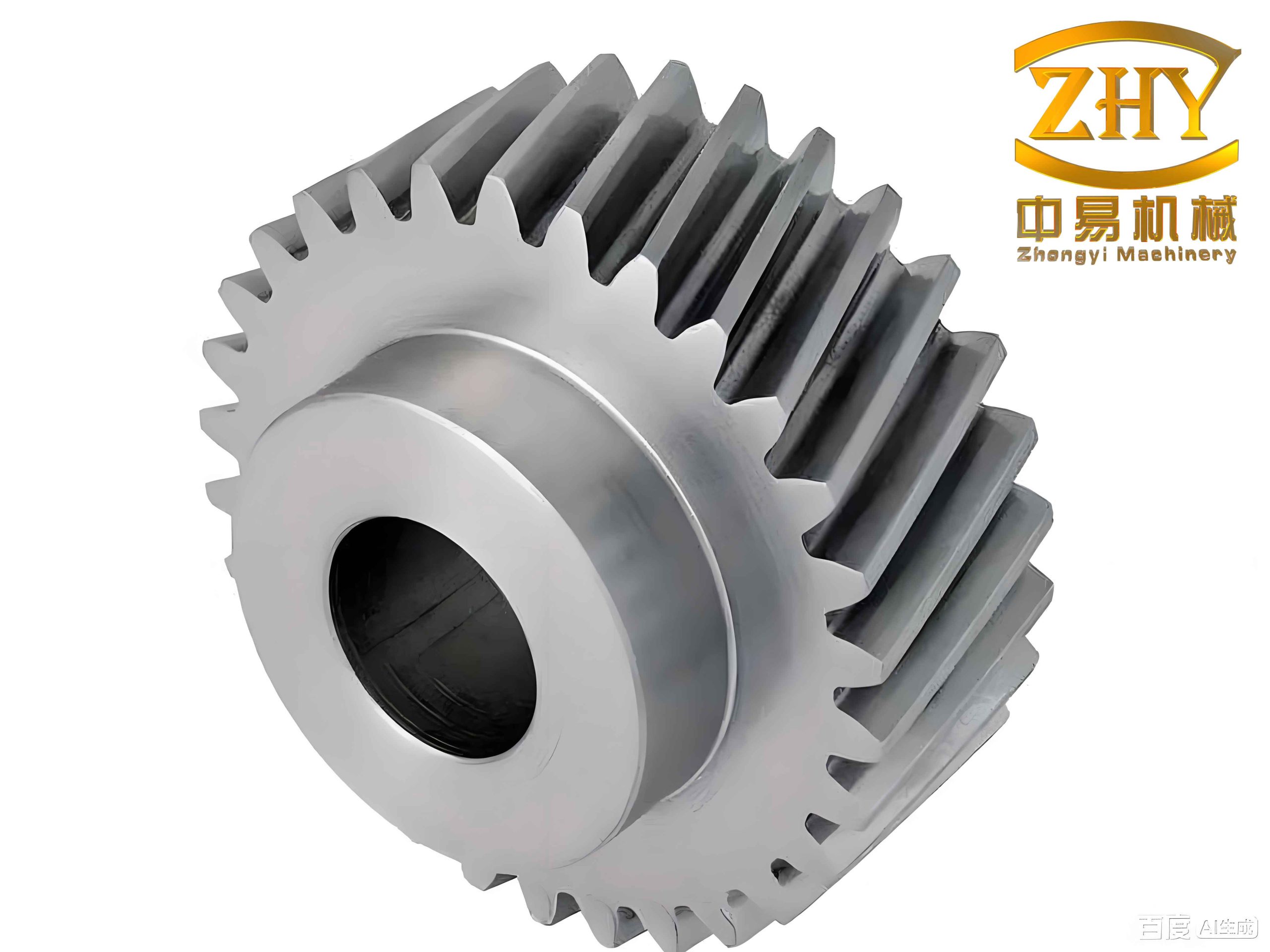
I begin from a simple observation: helical gears differ from spur gears because their contact lines are inclined relative to the tooth trace. This inclination makes the contact line length time-varying, the meshing stiffness smoother, and the load distribution more gradual. However, the same inclination also makes friction excitation more complicated. In my formulation, I combine a time-varying contact-line description, a load- and speed-dependent friction coefficient, a slice-based stiffness calculation, an eight-degree-of-freedom dynamic model, a stick-slip transition criterion, a linear wear-depth model, and a finite-element modal analysis. I use tables and equations throughout this article to summarize the logic and to make the parametric trends explicit.
Time-Varying Meshing Characteristics of Helical Gears
For helical gears, the total contact line length changes as successive tooth pairs enter and leave the meshing zone. I divide the meshing region into six zones according to the position of the contact line relative to the pitch line. Let $$\varepsilon_\alpha$$ be the transverse contact ratio, $$\varepsilon_\beta$$ the axial contact ratio, $$P_{bt}$$ the base pitch in the transverse plane, and $$s_i$$ the distance traveled by the $$i$$-th tooth pair along the actual line of action. When $$\varepsilon_\alpha > \varepsilon_\beta$$, I describe the left and right contact-line lengths $$a_1$$ and $$a_2$$ in a piecewise manner:
$$
\begin{aligned}
\text{Zone 1:} \quad & s_i < \frac{l_2}{\sin\beta}, &
a_1 &= \frac{s_i}{\sin\beta}, \quad a_2 = 0,\\
\text{Zone 2:} \quad & \frac{l_2}{\sin\beta} \le s_i < P_{bt}, &
a_1 &= \frac{l_2}{\sin\beta}, \quad a_2 = \frac{s_i-l_2}{\sin\beta},\\
\text{Zone 3:} \quad & P_{bt} \le s_i < P_{bt}+\frac{l_2}{\sin\beta}, &
a_1 &= \frac{s_i-P_{bt}+l_2}{\sin\beta}, \quad a_2 = \frac{l_2}{\sin\beta},\\
\text{Zone 4:} \quad & P_{bt}+\frac{l_2}{\sin\beta} \le s_i < P_{bt}+\frac{l_1}{\sin\beta}, &
a_1 &= \frac{l_1}{\sin\beta}, \quad a_2 = \frac{l_1}{\sin\beta},\\
\text{Zone 5:} \quad & P_{bt}+\frac{l_1}{\sin\beta} \le s_i < P_{bt}+\frac{l_m}{\sin\beta}, &
a_1 &= 0, \quad a_2 = \frac{l_m-s_i+P_{bt}}{\sin\beta},\\
\text{Zone 6:} \quad & P_{bt}+\frac{l_m}{\sin\beta} \le s_i < N P_{bt}, &
a_1 &= 0, \quad a_2 = 0.
\end{aligned}
$$
When $$\varepsilon_\alpha < \varepsilon_\beta$$, the same logic is used but the zone boundaries are controlled by the axial contact ratio rather than the transverse one. In my numerical experiments, I find that the total contact line length is not constant. It rises at entry, remains near a plateau, and falls at exit. This behavior explains why helical gears usually have smaller stiffness fluctuations than spur gears, but it also means that friction force changes continuously along the contact line.
| Parameter | Meaning in my helical gear model | Typical value or expression |
|---|---|---|
| $$\beta$$ | Helix angle | $$20^\circ$$ |
| $$b$$ | Tooth width | $$70\,\text{mm}$$ |
| $$m_n$$ | Normal module | $$7\,\text{mm}$$ |
| $$\alpha_n$$ | Normal pressure angle | $$26^\circ$$ |
| $$z_1/z_2$$ | Tooth number ratio | $$29/69$$ |
| $$a$$ | Center distance | $$363\,\text{mm}$$ |
| $$\varepsilon_\alpha$$ | Transverse contact ratio | $$\frac{L}{P_{bt}}$$ |
| $$\varepsilon_\beta$$ | Axial contact ratio | $$\frac{b\tan\beta}{P_t}$$ |
| $$L$$ | Total contact line length | $$a_1+a_2$$ |
I then calculate the time-varying friction excitation. I use a load- and speed-dependent friction coefficient based on elastohydrodynamic lubrication. The coefficient depends on the maximum contact pressure, sliding-to-rolling ratio, entrainment velocity, lubricant viscosity, equivalent curvature radius, and surface roughness. I write my working form as
$$
\mu = e^{f_h(SR,P_h,\nu_0,S)} P_h^{b_2}|SR|^{b_3} V_e^{b_4}\nu_0^{b_5} R^{b_6},
$$
$$
f_h = b_1 + b_4 |SR| P_h \lg(\nu_0) + b_5 e^{-|SR|P_h\lg(\nu_0)} + b_9 e^{S}.
$$
Here, $$P_h$$ is the maximum contact pressure, $$SR$$ is the sliding-to-rolling ratio, $$V_e$$ is the entrainment velocity, $$\nu_0$$ is the dynamic viscosity, $$S$$ is the composite root-mean-square roughness, and $$R$$ is the equivalent normal curvature radius. The regression coefficients I use are summarized in Table 2. This formula allows the friction coefficient to vary with meshing position, load, and speed, which is essential for helical gears under realistic operating conditions.
| Coefficient | Value | Coefficient | Value |
|---|---|---|---|
| $$b_1$$ | $$-8.92$$ | $$b_6$$ | $$-0.10$$ |
| $$b_2$$ | $$1.03$$ | $$b_7$$ | $$0.75$$ |
| $$b_3$$ | $$1.04$$ | $$b_8$$ | $$-0.39$$ |
| $$b_4$$ | $$-0.35$$ | $$b_9$$ | $$0.62$$ |
| $$b_5$$ | $$2.81$$ | $$\nu_0$$ | $$13.5\times10^{-3}\,\text{Pa}\cdot\text{s}$$ |
The maximum contact pressure in my model is obtained from an elliptical contact approximation:
$$
P_h = \sqrt{\frac{F_n E’}{\pi R L}},
$$
where $$E’$$ is the equivalent elastic modulus, $$L$$ is the contact line length, and $$F_n$$ is the normal meshing force. The normal force itself is computed from the meshing stiffness and damping:
$$
F_n(t) = K_m(t)\delta(t) + C_m(t)\dot{\delta}(t),
$$
where $$\delta(t)$$ is the relative deformation along the line of action. The friction force on a single tooth is then
$$
F_f(t) = \mu(t) F_n(t).
$$
I observe that the friction coefficient approaches zero at the pitch point because the relative sliding velocity vanishes there. Near the pitch point, the equivalent curvature radius increases and the sliding velocity decreases, so the friction coefficient decreases. Away from the pitch point, the curvature radius decreases and the sliding velocity increases, so the friction coefficient increases. In the alternating two-tooth and three-tooth meshing zones, the load shared by each tooth pair changes abruptly, and therefore the friction coefficient also changes abruptly. I summarize these trends in Table 3.
| Operating condition | Effect on friction coefficient | Physical reason |
|---|---|---|
| Load increases | $$\mu$$ increases | Higher contact pressure |
| Rotational speed increases | $$\mu$$ decreases | Higher entrainment velocity and film formation |
| Near pitch point | $$\mu \to 0$$ | Relative sliding velocity approaches zero |
| Two-tooth to three-tooth transition | $$\mu$$ jumps | Load sharing changes abruptly |
| Entry region compared with exit region | Entry $$\mu$$ is larger | Higher contact pressure and sliding ratio at entry |
I also study how geometric parameters of helical gears influence the time-varying excitation. The helix angle and tooth width are two of the most important parameters. When the helix angle increases, the total contact line length decreases, the axial contact ratio increases, and the total contact ratio increases. The maximum single-tooth friction decreases because the contact region is longer and the load is more uniformly distributed. When the tooth width increases, the total contact line length increases, the axial contact ratio increases, the transverse contact ratio remains unchanged, and the single-tooth friction decreases. These trends are essential for designing helical gears with low vibration and low wear.
| Geometric change | Total contact line length | Axial contact ratio | Transverse contact ratio | Single-tooth friction |
|---|---|---|---|---|
| Helix angle increases | Decreases | Increases | Decreases slightly | Decreases |
| Tooth width increases | Increases | Increases | Unchanged | Decreases |
| Load increases | Nearly unchanged | Nearly unchanged | Nearly unchanged | Increases |
| Speed increases | Nearly unchanged | Nearly unchanged | Nearly unchanged | Decreases |
Stick-Slip Friction Dynamics of Helical Gears
After establishing the time-varying friction excitation, I build a dynamic model of a helical gear pair that includes stick-slip friction. I use the potential energy method to calculate the time-varying meshing stiffness because it is accurate, computationally efficient, and suitable for gear fault analysis. I model a single tooth as a non-uniform cantilever beam. The total potential energy includes contact energy, bending energy, shear energy, axial compression energy, and fillet foundation energy. The corresponding stiffness components are denoted by $$k_h$$, $$k_b$$, $$k_s$$, $$k_a$$, and $$k_f$$. For a single tooth pair, I write
$$
\frac{1}{k_1} = \frac{1}{k_h} + \frac{1}{k_{b1}} + \frac{1}{k_{s1}} + \frac{1}{k_{a1}} + \frac{1}{k_{f1}} + \frac{1}{k_{b2}} + \frac{1}{k_{s2}} + \frac{1}{k_{a2}} + \frac{1}{k_{f2}}.
$$
The contact stiffness is approximated by
$$
k_h = \frac{\pi E b}{4(1-\nu^2)}.
$$
The bending, shear, and axial compression energies are
$$
U_b = \int_0^d \frac{F_b^2}{2k_b}\,dx,\quad
U_s = \int_0^d \frac{F_s^2}{2k_s}\,dx,\quad
U_a = \int_0^d \frac{F_a^2}{2k_a}\,dx.
$$
For helical gears, I use the slice method. I divide each tooth along the tooth width into several thin slices. Each slice is treated as a spur gear slice with a phase shift determined by the helix angle. The total meshing stiffness of helical gears at time $$t$$ is the sum of the stiffnesses of all slices currently in contact:
$$
K_m(t) = \sum_{j=1}^{N_s} k_j(t),
$$
where $$N_s$$ is the number of active slices. This approach reproduces the smooth stiffness variation of helical gears. Compared with spur gears, the stiffness curve of helical gears has smaller jumps and more gradual transitions. The multi-tooth contact effect improves load sharing and reduces the risk of severe vibration.
| Stiffness component | Physical meaning | Main influencing factors |
|---|---|---|
| $$k_h$$ | Contact compliance | Elastic modulus, tooth width, Poisson ratio |
| $$k_b$$ | Bending compliance | Tooth height, load position, section inertia |
| $$k_s$$ | Shear compliance | Shear modulus, section area |
| $$k_a$$ | Axial compression compliance | Normal force component, area |
| $$k_f$$ | Fillet foundation compliance | Root geometry, tooth root circle |
I then establish an eight-degree-of-freedom dynamic model for the helical gear pair. Each gear has translational degrees of freedom along the $$x$$, $$y$$, and $$z$$ directions and one rotational degree of freedom about the $$z$$ axis. The equations of motion are
$$
\begin{aligned}
m_1\ddot{x}_1 + K_{x1}x_1 + c_{x1}\dot{x}_1 &= f_p,\\
m_2\ddot{x}_2 + K_{x2}x_2 + c_{x2}\dot{x}_2 &= -f_g,\\
m_1\ddot{y}_1 + K_{y1}y_1 + c_{y1}\dot{y}_1 &= -F_n\sin\beta,\\
m_2\ddot{y}_2 + K_{y2}y_2 + c_{y2}\dot{y}_2 &= F_n\sin\beta,\\
m_1\ddot{z}_1 + K_{z1}z_1 + c_{z1}\dot{z}_1 &= -F_n\cos\beta,\\
m_2\ddot{z}_2 + K_{z2}z_2 + c_{z2}\dot{z}_2 &= F_n\cos\beta,\\
I_1\ddot{\theta}_1 &= T_1 – F_n\cos\beta\, r_{b1} + M_p,\\
I_2\ddot{\theta}_2 &= -T_2 + F_n\cos\beta\, r_{b2} – M_g.
\end{aligned}
$$
Here, $$m_i$$ and $$I_i$$ are the mass and moment of inertia of gear $$i$$, $$K_{xi}$$, $$K_{yi}$$, $$K_{zi}$$ are support stiffnesses, $$c_{xi}$$, $$c_{yi}$$, $$c_{zi}$$ are support damping coefficients, $$T_1$$ and $$T_2$$ are input and load torques, $$r_{bi}$$ are base circle radii, and $$M_p$$ and $$M_g$$ are friction torques. The relative deformation along the line of action is
$$
\delta = (y_1-y_2)\cos\beta + (r_{b1}\theta_1 – r_{b2}\theta_2)\cos\beta + (z_1-z_2)\sin\beta – e(t).
$$
The meshing force is
$$
F_n = K_m(t)\delta + C_m(t)\dot{\delta}.
$$
The friction force on the driving gear is
$$
f_p = \mu F_n \operatorname{sign}(v_r),
$$
where $$v_r$$ is the relative sliding velocity at the contact point. In a pure sliding model, the friction direction reverses only once near the pitch point. However, when I include vibration velocity, the relative velocity can reverse more than once. This is the key to stick-slip behavior in helical gears.
I propose a transition condition between adhesion and sliding states. The contact is in the sliding state when the tangential force exceeds the maximum static friction. The contact is in the adhesion state when the relative velocity is zero and the tangential force is below the maximum static friction. In my model, I write the transition condition as
$$
v_{M2M1} = v_r\sin\alpha_1 – \dot{x}_1 – v_r\sin\alpha_2 – \dot{x}_2 = 0,
$$
$$
f_{21}=f_{12}<f_{\max}=\mu $$=""
When these conditions are satisfied, the two teeth stick together. In the adhesion zone, the friction force is not determined by the sliding friction law but by the elastic force required to maintain zero relative velocity. I write the adhesion-state force as
$$
f_{21}=m_1\ddot{x}_1 + K_{x1}x_1 + c_{x1}\dot{x}_1,\quad
f_{12}=m_2\ddot{x}_2 + K_{x2}x_2 + c_{x2}\dot{x}_2.
$$
I find that the adhesion zone appears near the pitch point. In a sliding-only model, the relative velocity curve crosses zero once. In the stick-slip model, the relative velocity remains exactly zero over several short intervals. Under my nominal conditions, I observe up to four adhesion events within one meshing period. Under high speed and heavy load, adhesion becomes more frequent and lasts longer. This greatly increases the risk of adhesive wear in helical gears.
| Dynamic state | Relative velocity | Tangential force | Observed behavior in helical gears | |
|---|---|---|---|---|
| Sliding | $$v_{M2M1}\neq 0$$ | $$f=\mu f_n$$ | Friction follows sliding law | |
| Adhesion | $$v_{M2M1}=0$$ | $$f<f_{\max}$$ | Teeth stick near pitch point | |
| Transition | $$v_{M2M1}=0$$ | $$f=f_{\max}$$ | Slip initiates | |
| High speed | Frequent zero crossings | Rapid switching | More adhesion events | |
| Heavy load | Longer zero intervals | Higher maximum friction | Longer adhesion duration |
The dynamic response of helical gears changes significantly when stick-slip is included. In the sliding-only model, the single-tooth meshing force varies smoothly except for the load-sharing jumps. In the stick-slip model, the meshing force near the pitch point oscillates violently. I observe meshing force fluctuations between approximately $$10\,\text{kN}$$ and $$150\,\text{kN}$$ in my simulation. The single-tooth friction force also becomes more complex. In the adhesion zones, the friction force is controlled by the elastic restoring force, and it transitions between stick and slip states. This means that the classical sliding friction model is insufficient for helical gears operating under high-speed and heavy-load conditions.
| Model | Meshing force behavior | Friction force behavior | Main limitation |
|---|---|---|---|
| Sliding-only | Smooth with load-sharing jumps | Direction reverses once at pitch point | Ignores adhesion |
| Stick-slip | Strong oscillation near pitch point | Complex stick-slip transitions | Needs transition criterion |
| High-speed stick-slip | Frequent oscillations | Many short adhesion intervals | Higher vibration and wear risk |
| Heavy-load stick-slip | Large force amplitude | Long adhesion duration | High adhesive wear probability |
Wear Model and Numerical Simulation for Helical Gears
Wear in helical gears is a progressive material removal process. I classify the wear mechanisms as abrasive wear, adhesive wear, fatigue wear, corrosive wear, fretting wear, and erosive wear. In practice, several mechanisms act together. I use a linear wear-depth model based on the classical wear equation. The volumetric wear rate is
$$
\frac{dV}{dS} = K\frac{W}{H},
$$
where $$V$$ is the wear volume, $$S$$ is the relative sliding distance, $$W$$ is the normal load, $$H$$ is the hardness, and $$K$$ is the wear coefficient. For a contact point $$q$$ on the tooth surface, the wear depth is
$$
h_q = \int_0^s k p\,ds,
$$
where $$p$$ is the contact pressure and $$k$$ is the dimensional wear coefficient. In discrete form, I update the wear depth after each loading cycle as
$$
h_{q,n} = h_{q,n-1} + k P_{q,n-1} S_p.
$$
The contact pressure is obtained from an elliptical contact model. For two equivalent cylinders in contact, the contact half-width is
$$
a_h = \sqrt{\frac{4F_n}{\pi b E’}\rho},
$$
and the contact pressure is
$$
p = \frac{2F_t}{\pi a_h l},
$$
where $$F_t$$ is the tangential force, $$l$$ is the contact line length, $$\rho$$ is the equivalent curvature radius, and $$E’$$ is the equivalent elastic modulus. I then calculate the sliding distances for the driving and driven gears as
$$
S_p = a_h \frac{u_g-u_p}{u_p},\quad
S_g = a_h \frac{u_p-u_g}{u_g},
$$
where $$u_p$$ and $$u_g$$ are the circumferential velocities of the driving and driven gears. The sliding coefficients are
$$
\lambda_p = \frac{|S_p|}{|S_p|+|S_g|},\quad
\lambda_g = \frac{|S_g|}{|S_p|+|S_g|}.
$$
I simulate the wear process for helical gears with a tooth number ratio of $$29/69$$, normal module $$7\,\text{mm}$$, pressure angle $$26^\circ$$, helix angle $$20^\circ$$, center distance $$363\,\text{mm}$$, tooth width $$70\,\text{mm}$$, input speed $$1500\,\text{r/min}$$, and input torque $$2000\,\text{N}\cdot\text{m}$$. The wear depth after many cycles shows a V-shaped distribution along the tooth profile. The maximum wear appears near the tooth root and tooth tip, while the minimum wear appears near the pitch point. The reason is that the relative sliding distance is large at the root and tip, but near zero at the pitch point. I also find that the driving gear wears more than the driven gear because it has fewer teeth and therefore experiences more cycles in the same time.
| Region on tooth | Sliding coefficient | Relative sliding distance | Wear depth |
|---|---|---|---|
| Tooth root | Maximum | Large | Maximum |
| Pitch point | Zero | Approaches zero | Minimum |
| Tooth tip | Moderate to high | Large | High |
| Driving gear | Higher than driven | Higher than driven | Higher than driven |
| Driven gear | Lower than driving | Lower than driving | Lower than driving |
I study the influence of helix angle, tooth width, input torque, and load cycles on wear depth. When the helix angle increases, the contact line length increases, the unit line load decreases, and the average contact pressure becomes more uniform. As a result, the cumulative wear depth decreases. When the tooth width increases, the contact area increases, the unit line load decreases, and the wear depth decreases. When the input torque increases, the normal load at each contact point increases, the contact pressure increases, and the wear depth increases significantly. When the number of load cycles increases, the wear depth accumulates gradually. This accumulation is caused by repeated plastic deformation, fatigue crack growth, and material removal.
| Parameter change | Effect on contact pressure | Effect on wear depth |
|---|---|---|
| Helix angle increases | Decreases and becomes more uniform | Decreases |
| Tooth width increases | Decreases | Decreases |
| Input torque increases | Increases | Increases strongly |
| Load cycles increase | Repeated loading | Accumulates |
| Pressure angle increase | First decreases then increases | Minimum near pitch point |
Modal Characteristics of Helical Gears Under Wear
I perform modal analysis to understand how wear changes the natural frequencies and mode shapes of helical gears. The general dynamic equation is
$$
[M]\{\ddot{x}(t)\} + [C]\{\dot{x}(t)\} + [K]\{x(t)\} = \{f(t)\}.
$$
For modal analysis, I neglect damping and external excitation, so the free vibration equation becomes
$$
[M]\{\ddot{x}\} + [K]\{x\} = \{0\}.
$$
The eigenvalue problem is
$$
\det([K]-\omega^2[M])=0.
$$
The square roots of the eigenvalues give the natural frequencies, and the corresponding eigenvectors give the mode shapes. In my finite-element model, I use a three-dimensional solid model of the helical gear pair. The material has an elastic modulus of $$206\,\text{GPa}$$, a Poisson ratio of $$0.3$$, and a density of $$7850\,\text{kg/m}^3$$. I generate a tetrahedral mesh with $$255374$$ nodes and $$167657$$ elements. The average element quality is about $$0.88$$. I fix the gear hub inner surface to simulate the shrink-fit and keyed connection to the shaft. I then solve for the first eight modes using the block Lanczos method.
| Mode order | Natural frequency before wear (Hz) | Natural frequency after wear (Hz) | Observed shift |
|---|---|---|---|
| 1 | 217.92 | 236.97 | Increase |
| 2 | 346.53 | 364.12 | Increase |
| 3 | 598.66 | 607.75 | Small increase |
| 4 | 695.38 | 700.60 | Small increase |
| 5 | 1124.60 | 1132.20 | Increase |
| 6 | 1477.80 | 1482.30 | Increase |
| 7 | 2325.00 | 2376.30 | Large increase |
| 8 | 2619.40 | 2631.10 | Large increase |
I find that wear has a small influence on the overall mode shapes but a large influence on the natural frequencies. The first mode is a folding-type vibration. The second mode is a swing-type vibration about the $$y$$ axis, with almost no axial vibration and a ring-shaped end-face vibration. The third mode is a ring-shaped vibration about the $$z$$ axis. The fourth mode is a more complex folding-type vibration. The fifth and sixth modes are second-order axial folding vibrations. The seventh and eighth modes are third-order folding vibrations with polygonal end-face deformation and structural twisting. In the radial and folding modes, the deformation of the teeth and rim is much larger than that of other parts. This means that local tooth deformation becomes more important in higher-order modes.
| Mode order | Mode shape description | Influence of wear |
|---|---|---|
| 1 | Folding vibration | Frequency increases |
| 2 | Swing about $$y$$ axis with ring-like end face | Frequency increases |
| 3 | Ring-shaped vibration about $$z$$ axis | Small change |
| 4 | Complex folding vibration | Small change |
| 5–6 | Second-order axial folding | Moderate increase |
| 7–8 | Third-order folding with twisting | Large increase |
Dynamic Response of Helical Gears Under Wear
Wear changes the geometric shape of helical gears, which in turn changes stiffness excitation, error excitation, and impact excitation. I calculate the worn meshing stiffness by modifying the tooth thickness in the cantilever beam model. If $$h$$ is the original half tooth thickness, then the worn half thickness is
$$
h’ = h + h_{wi},
$$
where $$h_{wi}$$ is the wear depth on the $$i$$-th gear. The section inertia and area become
$$
I’_x = \frac{1}{12}(2h’)^3 b,\quad
A’_x = (2h’)b.
$$
I substitute these worn geometric parameters into the stiffness equations and obtain the worn meshing stiffness. The results show that wear reduces the single-tooth stiffness. The reduction is small at low wear levels but becomes more pronounced as wear increases. For the total meshing stiffness, the reduction in the three-tooth contact zone is larger than that in the two-tooth contact zone because the wear depths of three teeth are accumulated.
| Wear level | Single-tooth stiffness | Two-tooth total stiffness | Three-tooth total stiffness |
|---|---|---|---|
| No wear | Reference | Reference | Reference |
| Moderate wear | Slight decrease | Small decrease | Moderate decrease |
| Severe wear | Noticeable decrease | Moderate decrease | Large decrease |
I also include wear-induced transmission error. The total transmission error is
$$
e(t) = e_L + e_S + e_{ms} + e_{random},
$$
where $$e_L$$ is the long-period component, $$e_S$$ is the short-period component, $$e_{ms}$$ is the wear-induced component, and $$e_{random}$$ is the random component. I approximate these terms as
$$
e_L = F_i’ \sin(2\pi f_p t),\quad
e_S = f_i’ \sin(2\pi f_m t),\quad
e_{ms} = \min(h_{pi},h_{gi}),
$$
with a random term of the form $$0.2\,\text{rand}$$. Here, $$f_p$$ is the shaft rotation frequency and $$f_m$$ is the meshing frequency. I find that the static transmission error amplitude increases with wear. In my simulation, the worn transmission error amplitude becomes about $$1.5$$ times the initial amplitude. This increase directly affects the dynamic response of helical gears.
I analyze the dynamic response using time-domain curves, fast Fourier transform spectra, phase diagrams, and return-map sections. For a healthy helical gear pair, the time-domain response is nearly periodic. The frequency spectrum is dominated by the meshing frequency and its harmonics. The phase diagram shows a closed curve, and the return-map section shows a small number of discrete points. This indicates a single-periodic motion.
| Wear condition | Time-domain amplitude | Frequency spectrum | Phase diagram | Return-map section |
|---|---|---|---|---|
| No wear | Low and stable | Discrete meshing frequency lines | Closed curve | Single point |
| Moderate wear | Increased | Harmonics and sidebands grow | Wider closed band | Multiple points |
| Severe wear | Large fluctuations | Broadened sidebands and harmonics | Thick and complex band | Distributed points |
As wear increases, the time-domain amplitude grows, and the vibration becomes more severe. In the frequency spectrum, the meshing frequency and its multiples increase in amplitude. Sidebands appear around the meshing frequency, and their width expands with wear. The sidebands are spaced by the shaft rotation frequency and its multiples. In the phase diagram, the once-closed curve becomes a band with finite thickness. In the return-map section, the single point spreads into a multi-point or scattered set. These changes indicate a transition from periodic motion to quasi-periodic motion and eventually to a more complex or chaotic state.
I summarize the main dynamic response trends of helical gears under wear as follows. First, the static transmission error increases with wear. Second, the meshing stiffness decreases with wear, especially in the three-tooth contact zone. Third, the vibration amplitude increases, and the frequency spectrum becomes richer. Fourth, the phase trajectory becomes wider, and the return map becomes more scattered. Fifth, the dynamic behavior evolves from single-periodic to quasi-periodic and chaotic states. These observations are important for condition monitoring and fault diagnosis of helical gears.
| Response feature | No wear | Moderate wear | Severe wear |
|---|---|---|---|
| Amplitude | Low | Moderate | High |
| Meshing frequency amplitude | Reference | Increased | Strongly increased |
| Harmonics | Weak | Visible | Strong |
| Sidebands | Narrow | Expanded | Broad |
| Phase trajectory | Closed curve | Closed band | Complex band |
| Return-map points | Single point | Several points | Scattered points |
| Motion state | Periodic | Quasi-periodic | Chaotic tendency |
Integrated Interpretation
I interpret my results as a coupled chain: geometry controls the contact line and contact ratio; contact line and load control the friction coefficient; friction and vibration control the stick-slip transition; stick-slip and contact pressure control wear; wear controls stiffness and transmission error; stiffness and transmission error control the modal and dynamic responses of helical gears. This chain is not linear. A small increase in load can increase the contact pressure, which increases the friction coefficient, which increases the adhesion duration, which increases the wear depth, which reduces the stiffness, which increases the transmission error, which increases the vibration amplitude, and which again changes the contact pressure. This feedback loop is the reason why helical gears can exhibit complex nonlinear behavior even under nominally steady operating conditions.
In my view, the most important practical implications are the following. First, helical gears should be designed with sufficient contact ratio and appropriate helix angle to reduce single-tooth friction and wear. Second, lubrication conditions should be controlled carefully because adhesion and stick-slip are more likely under starved lubrication. Third, high-speed and heavy-load conditions should be avoided or compensated by surface treatment and improved cooling. Fourth, condition monitoring should pay attention not only to the meshing frequency but also to sidebands and return-map features, because wear changes the system from periodic to quasi-periodic behavior. Fifth, dynamic models of helical gears should include stick-slip and wear if they are intended to predict long-term vibration and reliability.
I conclude that the dynamic characteristics of helical gears cannot be fully understood by considering stiffness alone or friction alone. Stick-slip and wear are intrinsic parts of the contact process. When I include them, the predicted meshing force, friction force, natural frequencies, transmission error, and vibration response become more realistic. The resulting model provides a systematic way to evaluate how helical gears behave under different loads, speeds, helix angles, tooth widths, and wear cycles. It also provides a foundation for optimizing helical gears to achieve lower vibration, lower noise, longer life, and higher reliability.
| Research element | Method I used | Main output |
|---|---|---|
| Contact line length | Piecewise geometric model | Time-varying contact line and contact ratio |
| Friction coefficient | Elastohydrodynamic regression | Load- and speed-dependent friction |
| Meshing stiffness | Potential energy method and slice method | Time-varying stiffness of helical gears |
| Dynamic model | Eight-degree-of-freedom lumped model | Meshing force and friction force |
| Stick-slip | Transition criterion and adhesion force | Adhesion intervals near pitch point |
| Wear | Linear wear-depth integration | V-shaped wear distribution |
| Modal analysis | Finite-element eigenvalue solution | Natural frequency shifts under wear |
| Dynamic response | Time, frequency, phase, and return-map analysis | Periodic-to-quasi-periodic transition |
Overall, my study shows that helical gears are highly nonlinear tribo-dynamic systems. The interaction between stick-slip and wear changes the excitation, the stiffness, the modal properties, and the vibration state. I believe that this integrated perspective is necessary for the next generation of high-speed and heavy-load helical gears.