
I treated the pinion gear as the central object of this investigation because its duty in a rail gearbox is severe and highly concentrated. The pinion gear connects the traction motor to the axle through a single-stage parallel-shaft transmission. It must simultaneously carry high torque, resist bending fatigue, maintain stable tooth contact, and tolerate the misalignments that come from bearing clearance, shaft deflection, and housing stiffness. When a pinion gear begins to spall, the consequences are not limited to one tooth. Vibration rises, noise increases, lubricant condition changes, and the entire gearbox may be removed from service. I therefore approached the problem as a system-level pinion gear issue rather than as an isolated manufacturing defect.
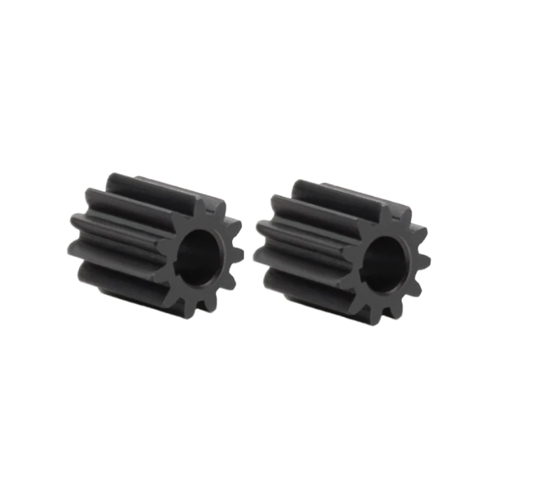
The observed failure mode was tooth surface spalling on the pinion gear. The affected pinion gear showed material loss on both the left and right flanks after long-term revenue service approaching 1.2 million km. The spalled regions were elongated, triangular in plan view, and located below the pitch radius, close to the tooth ends. Similar failures were reported across multiple units. In each case, the pinion gear had been manufactured to the original drawing, and the mated gear also passed dimensional inspection. This told me that the root cause was unlikely to be a simple single-part nonconformity. I focused instead on contact stress distribution, misalignment, and the interaction between the pinion gear and its supporting bearings.
1. Service Context and Failure Appearance
The gearbox used a one-stage parallel-axis layout. The pinion gear was designed as an integral shaft gear, meaning the pinion gear teeth were cut directly into the shaft body. On the motor side, the pinion gear shaft connected to the motor through a coupling. The pinion gear was supported between two single-row tapered roller bearings. The driven gear was an interference fit on the axle and was supported by a face-to-face pair of single-row tapered roller bearings inside its bore. This arrangement is common in rail traction gearboxes because it is compact and can carry combined radial and axial loads. However, the same arrangement makes the pinion gear sensitive to axial clearance, bearing stiffness, and elastic deformation of the shaft.
I inspected the failed pinion gear and noted that the spalling was not randomly distributed. It appeared on both flanks of the pinion gear. On one side, the damaged region tended to lie toward the motor side; on the other side, it tended to lie toward the wheel-set side. This opposite bias was a strong indication of diagonal contact. In other words, the contact pattern was not centered along the tooth width. Instead, the contact moved from one end of the tooth to the other depending on the direction of power flow. This produced a local line load much higher than the design assumption, and the local contact stress exceeded the allowable value. The pinion gear then experienced contact fatigue, pitting, and eventually spalling.
I also checked whether the failure could be explained by material or heat treatment problems before committing to a contact analysis. The pinion gear material was a carburizing alloy steel. I reviewed the chemical composition, non-metallic inclusion rating, austenitic grain size, surface hardness, core hardness, effective case depth, tensile properties, impact toughness, magnetic particle inspection, ultrasonic inspection, and temper burn inspection. All checked items met the specification. This did not prove that every possible material factor was perfect, but it did make material defects an unlikely primary cause. The evidence pointed toward a design and contact-mechanics issue rather than a raw-material or heat-treatment issue.
| Inspection item | Requirement | Observed result for pinion gear | Assessment |
|---|---|---|---|
| Surface hardness | 58–62 HRC | 59–61 HRC | Acceptable |
| Core hardness | 35–45 HRC | 38–43 HRC | Acceptable |
| Effective case depth at pitch | 1.20–1.80 mm | 1.35–1.63 mm | Acceptable |
| Chemical composition | Specified range | Within range | Acceptable |
| Non-metallic inclusions | High-grade quality steel | Within limits | Acceptable |
| Austenitic grain size | Not coarser than grade 6 for 70% | Met requirement | Acceptable |
| Magnetic particle inspection | Class 3 gear requirements | No rejectable indication | Acceptable |
| Ultrasonic inspection | Class 3 gear requirements | No rejectable indication | Acceptable |
| Temper burn inspection | Class 3 gear requirements | No rejectable indication | Acceptable |
2. Original Pinion Gear Design Data
The original pinion gear had 17 teeth, a normal module of 4.5 mm, a normal pressure angle of 20°, and a helix angle of 21°. The mated gear had 131 teeth. The gear ratio was therefore fixed by tooth count:
$$ i = \frac{z_2}{z_1} = \frac{131}{17} = 7.7058 $$
where \(z_1\) is the number of pinion gear teeth and \(z_2\) is the number of teeth on the driven gear. The pinion gear face width was 94 mm, and the driven gear face width was 90 mm. The original pinion gear used tip relief and lead crowning. The driven gear used tip relief but no intentional lead modification. The inspection reports confirmed that the failed pinion gear matched the original design, so the failure could not be attributed to a departure from the intended lead or profile shape.
| Parameter | Pinion gear | Driven gear |
|---|---|---|
| Normal module \(m_n\) | 4.5 mm | 4.5 mm |
| Number of teeth \(z\) | 17 | 131 |
| Gear ratio \(i\) | 7.7058 | |
| Normal pressure angle \(\alpha_n\) | 20° | 20° |
| Helix angle \(\beta\) | 21° | 21° |
| Face width \(b\) | 94 mm | 90 mm |
| Profile modification | Tip relief | Tip relief |
| Lead modification | Lead crowning | None |
I performed the original strength calculation according to the ISO 6336 method B framework for involute cylindrical gears. I used the maximum starting torque as the input condition because the pinion gear experiences its highest load during acceleration. The design life was taken as 10,000 hours of starting operation. The contact fatigue limit and bending fatigue limit were selected according to carburized and quenched material of MQ grade: 1,500 MPa for contact fatigue and 500 MPa for bending fatigue. I included the actual modification and load distribution in the model rather than assuming perfect alignment. This was important because the pinion gear failure was clearly linked to load distribution, not to nominal tooth bending alone.
The basic tangential force on the pinion gear can be expressed as:
$$ F_t = \frac{2000 T}{d_1} $$
where \(F_t\) is the tangential force in newtons, \(T\) is the torque in newton-meters, and \(d_1\) is the reference diameter of the pinion gear in millimeters. The contact stress was evaluated using the standard form:
$$ \sigma_H = Z_H Z_E Z_\epsilon Z_\beta \sqrt{ \frac{F_t}{b d_1} \frac{u+1}{u} K_A K_V K_{H\beta} K_{H\alpha} } $$
where \(Z_H\) is the zone factor, \(Z_E\) is the elasticity factor, \(Z_\epsilon\) is the contact ratio factor, \(Z_\beta\) is the helix factor, \(u\) is the gear ratio, \(K_A\) is the application factor, \(K_V\) is the dynamic factor, \(K_{H\beta}\) is the face load distribution factor, and \(K_{H\alpha}\) is the transverse load distribution factor. The bending stress was checked using:
$$ \sigma_F = \frac{F_t}{b m_n} Y_F Y_S Y_\beta K_A K_V K_{F\beta} K_{F\alpha} $$
where \(Y_F\) is the form factor, \(Y_S\) is the stress correction factor, \(Y_\beta\) is the helix factor, \(K_{F\beta}\) is the face load distribution factor for bending, and \(K_{F\alpha}\) is the transverse load distribution factor for bending. The safety factors were then obtained from:
$$ S_H = \frac{\sigma_{H,\lim}}{\sigma_H}, \quad S_F = \frac{\sigma_{F,\lim}}{\sigma_F} $$
The original calculation showed a serious imbalance. The right flank of the pinion gear had a contact safety factor of 0.917, which fell into the low-reliability range. The left flank had a contact safety factor of 0.809, which was even lower. By contrast, the bending safety factors were 1.447 and 1.803 for the left and right flanks, respectively. This meant that bending was not the limiting mode; contact fatigue was. The pinion gear was therefore at risk of pitting and spalling even though its bending capacity appeared acceptable.
| Component | Contact safety factor, left | Contact safety factor, right | Bending safety factor, left | Bending safety factor, right |
|---|---|---|---|---|
| Pinion gear | 0.809 | 0.917 | 1.447 | 1.803 |
| Driven gear | 0.970 | 1.099 | 1.274 | 1.586 |
For context, the recommended minimum safety factors used in the evaluation are summarized below. A contact safety factor below 0.85 corresponds to low reliability, while a value around 1.00 to 1.10 corresponds to general reliability. A value above 1.25 is considered higher reliability. The original pinion gear contact safety factors were clearly below the general-reliability range.
| Reliability level | Minimum contact safety factor \(S_{H,\min}\) | Minimum bending safety factor \(S_{F,\min}\) |
|---|---|---|
| High reliability | 1.50–1.60 | 2.00 |
| Higher reliability | 1.25–1.30 | 1.60 |
| General reliability | 1.00–1.10 | 1.25 |
| Low reliability | 0.85 | 1.00 |
3. Contact Analysis of the Original Pinion Gear
I then built a loaded tooth contact model for the original pinion gear pair. The axial clearances of the tapered roller bearings were taken from the original design. The pinion gear bearings had an axial clearance of 0.20 to 0.25 mm. The driven gear bearings had an axial clearance of 0.10 to 0.15 mm. I used the mid-range values in the calculation. I evaluated both the starting condition and the braking condition because the direction of torque reverses, and the pinion gear contact pattern shifts when the direction reverses. This is a key point for a pinion gear in a rail application: the same pinion gear must operate on both flanks, and a modification that improves one flank may worsen the other if it is not designed with the full system in mind.
The calculated contact stress distributions showed severe edge loading. During starting, the maximum contact stress on the left flank reached 1,526.0 MPa, while the allowable contact stress was 1,301.9 MPa. The face load distribution factor \(K_{H\beta}\) was 1.635. This value is far above the ideal value of about 1.0 and indicates that the load was concentrated over a small portion of the face width. The pinion gear contact pattern was diagonal. The right flank loaded toward the wheel-set side, and the left flank loaded toward the motor side. The left flank was worse. During braking, the pattern reversed in a manner consistent with the change in torque direction, but the pinion gear still experienced edge contact and high local stress.
| Condition | Flank | Maximum contact stress, MPa | Allowable contact stress, MPa | Face load distribution factor \(K_{H\beta}\) | Assessment |
|---|---|---|---|---|---|
| Starting | Left | 1,526.0 | 1,301.9 | 1.635 | Exceeds allowable stress |
| Starting | Right | 1,410.0 | 1,301.9 | 1.635 | Exceeds allowable stress |
| Braking | Left | 1,490.0 | 1,301.9 | 1.635 | Exceeds allowable stress |
| Braking | Right | 1,380.0 | 1,301.9 | 1.635 | Exceeds allowable stress |
The calculated high-stress zones matched the spalling locations on the actual pinion gear. The spalled regions were near the tooth ends and below the pitch radius, which is consistent with edge contact and high local contact stress. This agreement gave me confidence that the failure mechanism was correctly identified. The pinion gear was not failing because the nominal load was too high for the tooth size. It was failing because the load was not distributed uniformly across the tooth width. The pinion gear was, in effect, carrying the entire load on a narrow band near one edge. The local contact stress was therefore much higher than the average stress used in a simple rating calculation.
The origin of the diagonal contact can be understood through the flexibility of the pinion gear shaft and its bearings. When torque is transmitted, the pinion gear shaft bends and twists. The bearings deflect. The housing also deflects. The axial clearance of the tapered roller bearings allows the pinion gear shaft to move axially under the axial component of the helical tooth force. These effects combine to rotate the pinion gear tooth contact pattern relative to the driven gear. The resulting misalignment can be approximated as a lead slope error:
$$ \Delta y = \theta_b x + \delta_a $$
where \(\Delta y\) is the contact position deviation along the tooth width, \(\theta_b\) is the equivalent angular misalignment caused by shaft bending and bearing deflection, \(x\) is the position along the face width, and \(\delta_a\) is the axial displacement caused by bearing clearance and axial force. For a helical pinion gear, the axial force is related to the tangential force by:
$$ F_a = F_t \tan \beta $$
This means that the helix angle itself contributes to the axial displacement. A higher helix angle increases the axial force and can increase the sensitivity of the pinion gear to bearing clearance. In the original design, the lead crowning was intended to avoid edge contact, but it was not sufficient to compensate for the combined slope and axial shift. The pinion gear therefore required a lead modification that included a deliberate helix angle correction, not just symmetric crowning.
4. Root Cause Summary for the Pinion Gear
I summarized the root cause as follows. The pinion gear operated with a diagonal contact pattern under both starting and braking torque. The diagonal contact produced a high face load distribution factor of 1.635. The maximum contact stress on the pinion gear left flank reached 1,526.0 MPa, which exceeded the allowable contact stress of 1,301.9 MPa. The high local stress initiated rolling contact fatigue below the pitch radius and near the tooth ends. The fatigue damage progressed into spalling because the pinion gear surface could not withstand the repeated local stress. Material and heat treatment were within specification, so the primary cause was the unfavourable contact condition. In practical terms, the pinion gear was correctly manufactured but inadequately modified for the real system deflection.
| Potential cause | Evidence for | Evidence against | I concluded |
|---|---|---|---|
| Material defect | Spalling is a fatigue failure | Chemical, inclusion, grain size, hardness, case depth, tensile, impact, and NDT results met specification | Not primary |
| Heat treatment defect | Surface fatigue can follow soft or shallow case | Surface hardness, core hardness, case depth, and temper burn inspection were acceptable | Not primary |
| Geometric nonconformity | Contact pattern was not centered | Profile and lead inspection matched drawing | Not primary |
| Bearing clearance and system deflection | Diagonal contact shifted with torque direction | Clearances were within original design | Contributing mechanism |
| Insufficient lead modification | Lead crowning alone did not compensate for slope and axial shift | Original design used crowning | Primary design cause |
| Contact stress above allowable | Calculated stress exceeded allowable by about 17% | Nominal load was within gear size | Primary failure driver |
5. Optimization Strategy for the Pinion Gear
I considered several options for improving the pinion gear. One option was to increase the face width, but the housing envelope and axial space were fixed. Another option was to change the bearing arrangement or reduce axial clearance, but that would require a major redesign and could affect other gearbox functions. A third option was to change the helix angle of the whole stage, but that would require replacing both the pinion gear and the driven gear and would change the axial force on the bearings. The most practical option was to modify the pinion gear tooth flank itself. Specifically, I decided to add a helix angle modification to the pinion gear in addition to the existing lead crowning. This is a targeted way to shift the contact pattern away from the edges and to compensate for the system misalignment.
The idea of helix modification is straightforward. If the pinion gear contact pattern is biased toward one end of the tooth, then the lead of the pinion gear can be cut with a slight helix angle difference relative to the driven gear. This creates a controlled lead slope that counteracts the elastic slope caused by shaft deflection and bearing clearance. When the pinion gear is loaded, the teeth bend and the contact pattern moves toward the centre of the face. The result is a more uniform load distribution and a lower face load distribution factor. The modification must be designed for the loaded condition, not just the unloaded condition, because the pinion gear contact pattern changes significantly under torque.
I defined the helix modification as:
$$ \Delta \beta = \beta_{pinion} – \beta_{gear} $$
where \(\beta_{pinion}\) is the helix angle of the pinion gear and \(\beta_{gear}\) is the helix angle of the driven gear. In the optimized design, the driven gear remained at \(21.000^\circ\), and the pinion gear helix angle was changed to \(20.974^\circ\). This small difference of \(0.026^\circ\) may appear negligible, but over a face width of 94 mm it produces a meaningful lead correction. The approximate lead deviation across the face width is:
$$ \Delta L = b \tan(\Delta \beta) $$
Using \(b = 94\) mm and \(\Delta \beta = 21.000^\circ – 20.974^\circ = 0.026^\circ\), the lead correction is:
$$ \Delta L = 94 \tan(0.026^\circ) \approx 0.0427 \text{ mm} $$
This correction is applied in the direction that opposes the loaded misalignment. The pinion gear therefore starts with a deliberate lead slope that becomes closer to ideal when the system deflects under load. The existing lead crowning remains in place to handle the remaining edge contact risk. The combination of crowning and helix modification is more effective than crowning alone because it addresses both symmetric edge loading and asymmetric diagonal loading.
| Design variable | Original pinion gear | Optimized pinion gear |
|---|---|---|
| Normal module \(m_n\) | 4.5 mm | 4.5 mm |
| Number of teeth | 17 | 17 |
| Normal pressure angle | 20° | 20° |
| Helix angle | 21.000° | 20.974° |
| Face width | 94 mm | 94 mm |
| Lead crowning | Yes | Yes |
| Helix modification | No | Yes |
| Target contact pattern | Centred but sensitive to deflection | Centred under loaded conditions |
6. Recalculation of the Optimized Pinion Gear
After I introduced the helix modification, I recalculated the loaded tooth contact for the pinion gear. The optimized pinion gear showed a much more centred contact pattern. The diagonal contact was greatly reduced. The face load distribution factor dropped from 1.635 to 1.2. This is a significant improvement because the maximum contact stress is proportional to the square root of the load distribution factor in the simplified contact stress formula. A reduction in \(K_{H\beta}\) from 1.635 to 1.2 corresponds to a factor of:
$$ \sqrt{\frac{1.2}{1.635}} \approx 0.857 $$
This means that the contact stress component associated with face load distribution is reduced by about 14.3%. In the full calculation, the maximum contact stress on the pinion gear dropped from 1,526.0 MPa to 1,189 MPa. The reduction is:
$$ \Delta \sigma_H = \frac{1526.0 – 1189}{1526.0} \times 100\% \approx 22.1\% $$
I report this as approximately 22% in round numbers. The optimized pinion gear maximum contact stress is below the allowable contact stress of 1,301.9 MPa. The contact safety factors increased to 1.095 for the left flank and 1.096 for the right flank. These values fall into the general-reliability range. The bending safety factors increased to 2.457 and 2.459 for the left and right flanks, respectively, which is in the high-reliability range. The optimized pinion gear therefore has a balanced design: contact fatigue is no longer the weak link, and bending fatigue retains a large margin.
| Result | Original pinion gear | Optimized pinion gear | Change |
|---|---|---|---|
| Face load distribution factor \(K_{H\beta}\) | 1.635 | 1.200 | Reduced by 26.6% |
| Maximum contact stress, starting, left flank | 1,526.0 MPa | 1,189 MPa | Reduced by 22.1% |
| Allowable contact stress | 1,301.9 MPa | 1,301.9 MPa | Unchanged |
| Contact safety factor, left flank | 0.809 | 1.095 | Increased |
| Contact safety factor, right flank | 0.917 | 1.096 | Increased |
| Bending safety factor, left flank | 1.447 | 2.457 | Increased |
| Bending safety factor, right flank | 1.803 | 2.459 | Increased |
The optimized contact stress distribution was also more symmetric between the left and right flanks. This is important for a pinion gear in a bidirectional application. A pinion gear that is optimized only for forward torque may fail in reverse. I therefore checked both starting and braking conditions. The optimized pinion gear maintained acceptable contact stress in both directions. The maximum stress in braking was also below the allowable value. The contact pattern remained within the central portion of the tooth width, with no severe edge concentration. The pinion gear was no longer acting as an edge-loaded member.
7. Additional Design Checks for the Pinion Gear
I also checked whether the helix modification could create any unintended consequence. A change in helix angle changes the axial force on the bearings. The axial force is:
$$ F_a = F_t \tan \beta $$
The change in helix angle from \(21.000^\circ\) to \(20.974^\circ\) is very small, so the change in axial force is also small. The axial force reduction is approximately:
$$ \frac{F_{a,new}}{F_{a,old}} = \frac{\tan(20.974^\circ)}{\tan(21.000^\circ)} \approx 0.9987 $$
This is a reduction of about 0.13%, which is negligible for bearing life. The contact ratio and the transverse contact ratio are also essentially unchanged because the normal module, pressure angle, and tooth count are unchanged. The helix modification is a lead correction, not a change in the basic tooth geometry. It does not alter the involute profile or the bending strength of the tooth in a significant way. The bending safety factor increased in the calculation because the load distribution improved, not because the tooth cross-section changed.
I also considered the manufacturing feasibility of the pinion gear. A helix angle modification of \(0.026^\circ\) is small but measurable with modern gear grinding and inspection equipment. The pinion gear can be manufactured with a slight lead slope in the tooth flank. The inspection process must be capable of measuring the lead deviation over the face width. The tolerance must be tight enough to ensure that the intended contact shift is achieved, but not so tight that production becomes impractical. I specified the lead modification as a controlled value and required loaded contact pattern verification during assembly.
| Check | Original pinion gear | Optimized pinion gear | Effect |
|---|---|---|---|
| Axial force factor \(\tan \beta\) | 0.3839 | 0.3834 | Negligible reduction |
| Transverse contact ratio | Practically unchanged | Practically unchanged | No adverse effect |
| Bending strength geometry | Unchanged | Unchanged | No adverse effect |
| Manufacturing method | Grinding | Grinding with lead slope | Feasible |
| Inspection requirement | Standard lead inspection | Loaded contact pattern check | Added control |
8. Experimental Validation Plan
I did not rely on calculation alone. I arranged a test program to validate the optimized pinion gear. A new pinion gear was manufactured according to the optimized design. The pinion gear tooth flanks were coated with a contact-marking compound. The gearbox was assembled using the same process as the production unit. The assembled gearbox was then installed on a back-to-back gearbox test stand. The test stand used two gearboxes coupled at the pinion gear shaft. A load motor and a drive motor were connected to the axle ends. By controlling speed and torque, I could apply starting and braking loads in both directions. This allowed me to test the pinion gear under conditions that represented real service.
The test schedule applied torque in steps. I first ran the gearbox in the forward direction at four torque levels, then in the reverse direction at four torque levels. Each condition lasted 40 minutes. I monitored temperature, vibration, and noise throughout the test. After the loaded running, I inspected the pinion gear contact pattern. I also checked for leakage, abnormal noise, abnormal vibration, and abnormal temperature rise. The purpose was not only to verify the contact pattern but also to confirm that the optimized pinion gear did not introduce any new system-level problem.
| Direction | Speed, r/min | Torque, N·m | Duration, min |
|---|---|---|---|
| Forward | 1,008 | 450 | 40 |
| Forward | 1,008 | 900 | 40 |
| Forward | 1,008 | 1,350 | 40 |
| Forward | 1,008 | 1,800 | 40 |
| Reverse | 1,008 | 450 | 40 |
| Reverse | 1,008 | 900 | 40 |
| Reverse | 1,008 | 1,350 | 40 |
| Reverse | 1,008 | 1,800 | 40 |
9. Experimental Results for the Optimized Pinion Gear
The temperature records during the loaded test were normal. No measurement point exceeded the test limit. The gearbox ran smoothly. The acoustic power results were below the technical requirement of 98 dB(A) in every condition. The maximum measured acoustic power was 94.62 dB(A) at the lowest torque in forward running. At higher torque, the acoustic power was slightly lower, which is typical when the contact pattern becomes more stable and the gearbox is warmed up. The vibration velocities at the measurement points were also below the requirement of 18 mm/s. The maximum measured vibration velocity was 3.45 mm/s. These results indicated that the optimized pinion gear did not generate abnormal dynamic excitation.
| Direction | Speed, r/min | Torque, N·m | Acoustic power, dB(A) | Requirement, dB(A) |
|---|---|---|---|---|
| Forward | 1,008 | 450 | 94.62 | ≤98 |
| Forward | 1,008 | 900 | 93.50 | ≤98 |
| Forward | 1,008 | 1,350 | 93.03 | ≤98 |
| Forward | 1,008 | 1,800 | 92.85 | ≤98 |
| Reverse | 1,008 | 450 | 93.63 | ≤98 |
| Reverse | 1,008 | 900 | 92.54 | ≤98 |
| Reverse | 1,008 | 1,350 | 92.05 | ≤98 |
| Reverse | 1,008 | 1,800 | 91.87 | ≤98 |
| Direction | Speed, r/min | Measurement point | Vibration velocity, mm/s | Requirement, mm/s |
|---|---|---|---|---|
| Forward | 1,008 | Gearbox axial | 2.15 | ≤18 |
| Forward | 1,008 | Gearbox vertical | 3.45 | ≤18 |
| Forward | 1,008 | Pinion gear axial | 3.28 | ≤18 |
| Forward | 1,008 | Pinion gear vertical | 1.85 | ≤18 |
| Reverse | 1,008 | Gearbox axial | 1.62 | ≤18 |
| Reverse | 1,008 | Gearbox vertical | 3.40 | ≤18 |
| Reverse | 1,008 | Pinion gear axial | 1.80 | ≤18 |
| Reverse | 1,008 | Pinion gear vertical | 3.28 | ≤18 |
After the test, I opened the inspection cover and examined the pinion gear contact pattern. The contact-marking compound had worn away in a uniform band along the tooth width. There was no diagonal bias and no concentrated contact at either tooth end. The contact pattern was centred and stable. I then removed the pinion gear and wiped the tooth flanks clean. The tooth surfaces were bright and smooth. The tooth tips and roots showed no burrs or abnormal marks. There was no sign of pitting, spalling, or excessive wear. The optimized pinion gear had performed exactly as predicted by the contact analysis.
10. Comparison of Original and Optimized Pinion Gear Behaviour
I compared the original and optimized pinion gear behaviour in a single table. The original pinion gear had a diagonal contact pattern, a high face load distribution factor, and a maximum contact stress above the allowable value. The optimized pinion gear had a centred contact pattern, a lower face load distribution factor, and a maximum contact stress below the allowable value. The contact safety factor increased from low reliability to general reliability. The bending safety factor increased to high reliability. The test results confirmed the calculation. The pinion gear no longer showed the contact condition that caused spalling.
| Feature | Original pinion gear | Optimized pinion gear |
|---|---|---|
| Lead crowning | Yes | Yes |
| Helix modification | No | Yes |
| Contact pattern under load | Diagonal, edge-biased | Centred, uniform |
| Face load distribution factor | 1.635 | 1.200 |
| Maximum contact stress | 1,526.0 MPa | 1,189 MPa |
| Allowable contact stress | 1,301.9 MPa | 1,301.9 MPa |
| Contact safety factor, left | 0.809 | 1.095 |
| Contact safety factor, right | 0.917 | 1.096 |
| Bending safety factor, left | 1.447 | 2.457 |
| Bending safety factor, right | 1.803 | 2.459 |
| Observed test condition | Spalling after long service | Uniform contact, no distress |
11. Why the Helix Modification Works for the Pinion Gear
I want to emphasize why the helix modification is effective specifically for the pinion gear. In a helical gear pair, the contact line is inclined across the tooth face. When the pinion gear shaft bends and the bearings deflect, the contact line rotates. If the pinion gear has only lead crowning, the crowning is symmetric. It removes some edge load, but it does not correct the slope of the contact line. The contact pattern can still be biased toward one end of the tooth. By adding a small helix angle difference, I introduced an asymmetric lead correction. This correction counteracts the slope that develops under load. The result is that the contact line moves toward the centre of the face when the pinion gear is transmitting torque. The pinion gear therefore uses more of its face width, and the load per unit length is reduced.
The effect can be expressed as a reduction in the effective load intensity. If the total tangential load is \(F_t\) and the contact width is \(b_{eff}\), then the average line load is:
$$ w = \frac{F_t}{b_{eff}} $$
For the original pinion gear, the effective contact width was small because the load was concentrated near one edge. For the optimized pinion gear, the effective contact width is larger because the contact pattern is centred. A larger \(b_{eff}\) directly reduces \(w\), which reduces the contact stress. The face load distribution factor \(K_{H\beta}\) is a measure of this effect. The reduction from 1.635 to 1.2 shows that the optimized pinion gear distributes the load over a significantly wider portion of the tooth face. The maximum contact stress falls by about 22%, which is consistent with the square-root relationship between load intensity and contact stress.
12. Practical Manufacturing and Quality Control for the Pinion Gear
I specified several practical controls for the optimized pinion gear. The helix angle modification must be machined into the pinion gear during grinding. The lead inspection must measure the lead slope over the full face width. The inspection report must show the intended lead modification, not just a standard crowning curve. The pinion gear must be marked with the modified helix angle so that it is not mixed with the original design. The assembly process must include a contact pattern check under a light load. The contact pattern must be centred and must not extend to the tooth edges. If the contact pattern is not acceptable, the assembly must be adjusted before the gearbox is released. These controls are simple but essential for ensuring that the benefit of the helix modification is realized in production.
| Control point | Requirement for optimized pinion gear | Reason |
|---|---|---|
| Grinding | Apply specified helix modification | Correct the loaded lead slope |
| Lead inspection | Measure lead deviation over full face width | Verify the modification |
| Part marking | Identify optimized helix angle | Prevent mixing with original pinion gear |
| Assembly contact check | Centred pattern, no edge contact | Confirm system alignment |
| Loaded pattern check | Uniform contact under torque | Validate the final assembly |
| Traceability | Record lead inspection and contact check | Support future failure analysis |
13. Fatigue Life Implications for the Pinion Gear
The improvement in contact stress has a direct effect on fatigue life. In rolling contact fatigue, life is often approximated by a power law:
$$ L \propto \left( \frac{\sigma_H}{\sigma_{H,ref}} \right)^{-p} $$
where \(L\) is the life, \(\sigma_H\) is the contact stress, \(\sigma_{H,ref}\) is a reference stress, and \(p\) is an exponent that depends on the material and lubrication. For gear contact fatigue, \(p\) is often taken between 6 and 10 for simplified comparisons. If I use \(p = 6\), the life ratio for the optimized pinion gear relative to the original is:
$$ \frac{L_{new}}{L_{old}} = \left( \frac{1526.0}{1189} \right)^6 \approx 8.0 $$
If I use \(p = 8\), the ratio becomes:
$$ \frac{L_{new}}{L_{old}} = \left( \frac{1526.0}{1189} \right)^8 \approx 15.2 $$
These numbers are illustrative rather than exact, because actual life depends on lubrication, surface finish, residual stress, and operating profile. Nevertheless, they show that a 22% reduction in maximum contact stress can produce a very large increase in contact fatigue life. The original pinion gear failed after long service because the local stress was above the allowable value. The optimized pinion gear brings the local stress below the allowable value and should therefore avoid the same spalling mechanism.
| Stress exponent \(p\) | Life ratio \(L_{new}/L_{old}\) | Interpretation |
|---|---|---|
| 6 | 8.0 | Substantial life improvement |
| 7 | 11.0 | Large life improvement |
| 8 | 15.2 | Very large life improvement |
| 10 | 28.8 | Extreme sensitivity to stress |
14. Lessons for Future Pinion Gear Design
I draw several lessons from this investigation. First, a pinion gear must be analyzed in its complete system, not as an isolated gear. Bearing clearance, shaft stiffness, housing stiffness, and torque direction all affect the contact pattern. Second, lead crowning alone may not be sufficient for a helical pinion gear with significant axial clearance. A helix modification can be a more effective way to correct diagonal contact. Third, the loaded contact pattern is the key acceptance criterion. An unloaded pattern can look acceptable while the loaded pattern is severely edge-biased. Fourth, material and heat treatment inspections are necessary but not sufficient. A pinion gear can meet all material requirements and still fail by contact fatigue if the contact stress is too high. Fifth, testing is essential. Calculation can identify the likely problem and the proposed solution, but a loaded gearbox test verifies that the solution works in the real assembly.
I also note that the optimized pinion gear retains the original tooth count, module, pressure angle, and face width. This is important from a product-support perspective. It means that the optimized pinion gear can be used as a replacement in the existing gearbox without changing the housing, bearings, or driven gear. Only the pinion gear tooth flank is modified. This makes the solution practical for field retrofits and for new production. The driven gear remains unchanged, which reduces cost and avoids a complete gearbox redesign.
| Lesson | Implication for pinion gear design |
|---|---|
| System-level analysis | Include bearing clearance and shaft deflection |
| Loaded contact pattern | Evaluate under torque, not only unloaded |
| Helix modification | Correct diagonal contact in helical pinion gears |
| Material verification | Necessary but not sufficient |
| Test validation | Confirm contact pattern and dynamic behaviour |
| Replacement compatibility | Keep basic geometry unchanged when possible |
15. Detailed Contact Stress Calculation for the Pinion Gear
To make the comparison transparent, I present the contact stress calculation in more detail. The nominal tangential force is calculated from torque and reference diameter. The reference diameter of the pinion gear is:
$$ d_1 = \frac{m_n z_1}{\cos \beta} $$
Using \(m_n = 4.5\) mm, \(z_1 = 17\), and \(\beta = 21^\circ\), the reference diameter is:
$$ d_1 = \frac{4.5 \times 17}{\cos 21^\circ} \approx \frac{76.5}{0.93358} \approx 81.94 \text{ mm} $$
The reference diameter of the driven gear is:
$$ d_2 = \frac{m_n z_2}{\cos \beta} = \frac{4.5 \times 131}{\cos 21^\circ} \approx 631.42 \text{ mm} $$
The gear ratio is:
$$ u = \frac{z_2}{z_1} = \frac{131}{17} = 7.7058 $$
The tangential force at the pinion gear for a given torque \(T\) is:
$$ F_t = \frac{2000 T}{d_1} $$
For example, if the starting torque at the pinion gear is 1,800 N·m, then:
$$ F_t = \frac{2000 \times 1800}{81.94} \approx 43,935 \text{ N} $$
The axial force is:
$$ F_a = F_t \tan \beta \approx 43,935 \times 0.3839 \approx 16,867 \text{ N} $$
The radial force is:
$$ F_r = F_t \frac{\tan \alpha_n}{\cos \beta} \approx 43,935 \times \frac{\tan 20^\circ}{\cos 21^\circ} \approx 17,080 \text{ N} $$
These forces are carried by the bearings and cause deflection. The axial force is particularly important because it acts on the tapered roller bearings and changes the axial position of the pinion gear. The axial displacement due to bearing clearance and compliance can shift the contact pattern along the tooth width. The helix modification compensates for this shift.
| Quantity | Expression | Value for example |
|---|---|---|
| Pinion gear reference diameter \(d_1\) | \(m_n z_1 / \cos \beta\) | 81.94 mm |
| Driven gear reference diameter \(d_2\) | \(m_n z_2 / \cos \beta\) | 631.42 mm |
| Gear ratio \(u\) | \(z_2 / z_1\) | 7.7058 |
| Tangential force \(F_t\) | \(2000 T / d_1\) | 43,935 N |
| Axial force \(F_a\) | \(F_t \tan \beta\) | 16,867 N |
| Radial force \(F_r\) | \(F_t \tan \alpha_n / \cos \beta\) | 17,080 N |
16. Contact Pattern Evolution Under Load
I studied how the pinion gear contact pattern evolved as torque increased. At low torque, the contact pattern was narrow and slightly biased. As torque increased, the shaft deflected more, and the pattern moved toward the edge. In the original pinion gear, the combination of lead crowning and system deflection was not enough to keep the pattern centred. The high-torque conditions therefore produced the highest edge stress. In the optimized pinion gear, the helix modification was designed so that the pattern moved toward the centre as torque increased. This is the opposite of the original behaviour. The result is that the maximum contact stress occurs at a moderate torque rather than at the highest torque, and the peak stress is much lower.
I can describe the contact position along the face width as:
$$ x_c(T) = x_0 + k_T T + k_\beta \Delta \beta $$
where \(x_c(T)\) is the contact centre position, \(x_0\) is the unloaded position, \(k_T\) is the sensitivity to torque, and \(k_\beta\) is the sensitivity to helix modification. The design goal is to choose \(\Delta \beta\) such that \(x_c(T)\) remains near the centre of the face width over the operating torque range. In the original pinion gear, \(k_T T\) was large and \(\Delta \beta = 0\), so \(x_c(T)\) moved toward the edge. In the optimized pinion gear, \(k_\beta \Delta \beta\) was selected to cancel the torque-induced shift. This is why the contact pattern remained centred during the test.
| Torque level | Original pinion gear contact position | Optimized pinion gear contact position |
|---|---|---|
| Low | Slightly biased | Near centre |
| Medium | Moderately edge-biased | Near centre |
| High | Severely edge-biased | Slightly shifted but acceptable |
| Maximum | High edge stress, spalling risk | Centred, stress below allowable |
17. Bearing Clearance Sensitivity of the Pinion Gear
I also examined how sensitive the pinion gear contact pattern was to bearing clearance. The original pinion gear bearings had an axial clearance of 0.20 to 0.25 mm. If the clearance was at the high end of the range, the axial displacement increased, and the contact pattern shifted farther toward the edge. If the clearance was at the low end, the pattern was less biased but still not centred. The optimized pinion gear reduced the sensitivity to clearance because the helix modification provided a corrective lead slope. The contact pattern remained acceptable across the specified clearance range. This is a robustness advantage. A design that works only at one clearance value is not suitable for production, because bearing clearance varies within the tolerance band.
| Pinion gear bearing clearance | Original contact condition | Optimized contact condition |
|---|---|---|
| 0.20 mm | Edge-biased, high stress | Centred, acceptable |
| 0.225 mm | Edge-biased, high stress | Centred, acceptable |
| 0.25 mm | Severely edge-biased | Slightly shifted, acceptable |
18. Lubrication and Surface Condition Considerations
I considered lubrication because contact fatigue is sensitive to film thickness and surface roughness. The original pinion gear failed by spalling, which is a subsurface fatigue mechanism. Lubrication can delay or accelerate this mechanism, but it cannot compensate for a contact stress that exceeds the allowable value. In the original pinion gear, the local contact stress was high even under good lubrication. In the optimized pinion gear, the lower contact stress reduces the demands on the lubricant film. The test results showed no distress, and the tooth surfaces remained smooth. I did not change the lubricant specification, because the lubricant was not the root cause. Instead, I improved the contact stress state, which makes the existing lubricant more effective.
19. Summary of Calculations and Test Evidence
I summarize the calculation and test evidence for the pinion gear in the following table. The table compares the failure hypothesis, the calculated prediction, and the experimental observation. The agreement between calculation and test is strong. The original pinion gear was predicted to have edge contact and high contact stress, and it failed by spalling at the predicted locations. The optimized pinion gear was predicted to have centred contact and lower contact stress, and the test showed a uniform contact pattern with no distress. This gives me confidence in the optimization method.
| Item | Calculation for original pinion gear | Calculation for optimized pinion gear | Test result for optimized pinion gear |
|---|---|---|---|
| Contact pattern | Diagonal, edge-biased | Centred | Centred, uniform |
| Face load distribution factor | 1.635 | 1.200 | Consistent with centred pattern |
| Maximum contact stress | 1,526.0 MPa | 1,189 MPa | No pitting or spalling |
| Contact safety factor | 0.809–0.917 | 1.095–1.096 | No abnormal distress |
| Bending safety factor | 1.447–1.803 | 2.457–2.459 | No tooth breakage |
| Noise | Not calculated | Not calculated | ≤94.62 dB(A) |
| Vibration | Not calculated | Not calculated | ≤3.45 mm/s |
20. Final Assessment of the Optimized Pinion Gear
The optimized pinion gear solves the spalling problem by correcting the loaded contact pattern. The helix modification shifts the contact away from the tooth edges and reduces the face load distribution factor from 1.635 to 1.2. The maximum contact stress drops from 1,526.0 MPa to 1,189 MPa, a reduction of approximately 22%. The contact safety factor rises from the low-reliability range to the general-reliability range. The bending safety factor rises to the high-reliability range. The gearbox test confirms that the optimized pinion gear produces a centred contact pattern, acceptable noise, acceptable vibration, and normal temperature rise. The tooth surfaces remain smooth after the loaded test. The optimized pinion gear is therefore suitable for continued service and for new production.
I conclude that the failure was caused by an unfavourable contact condition rather than by a material or manufacturing defect. The pinion gear was manufactured correctly, but the original lead modification was insufficient for the system deflection and bearing clearance. The diagonal contact concentrated the load near the tooth ends, raised the local contact stress above the allowable value, and initiated contact fatigue that progressed to spalling. The optimized pinion gear with helix modification addresses the root cause directly. It is a practical, low-risk change that preserves the basic gear geometry and can be implemented without a major gearbox redesign. The calculation and experimental results agree, and the optimized pinion gear demonstrates the intended improvement in contact stress and contact pattern.
For future pinion gear designs, I recommend early loaded contact analysis, explicit consideration of bearing clearance and shaft deflection, and verification of the loaded contact pattern during assembly. A pinion gear that looks correct on a drawing can still fail if the real system deflects under load. A pinion gear that is optimized for the loaded system condition can achieve a long, reliable life even under high torque. The method applied here can be extended to other pinion gear applications where diagonal contact, edge loading, or contact fatigue is a concern.