
I performed a systematic failure investigation on a 20CrMnTi pinion gear that fractured during service. The pinion gear was part of a mechanical transmission assembly intended to transfer torque, change speed, and alter the direction of motion between two shafts. Because the pinion gear operated under repeated meshing contact, alternating bending stress, contact stress, and torsional loading, its premature fracture required a detailed root-cause assessment. My analysis combined chemical composition testing, macroscopic fracture appearance examination, scanning electron microscopy of the fracture surface, macroscopic structure inspection, metallographic observation, and hardened-layer depth measurement. The purpose was not merely to describe the broken pinion gear but to identify the dominant failure mode, determine whether the material or heat treatment contributed to the fracture, and propose corrective actions for future pinion gear production and service.
I found that the failed pinion gear did not exhibit a single isolated defect. Instead, the fracture resulted from a combination of brittle fracture mechanisms and insufficient load-bearing capacity in the gear core. The fracture mode was primarily transgranular fracture combined with quasi-cleavage brittle fracture. In addition, the carburized layer depth, tooth-surface hardness, and core hardness of the pinion gear all remained below the specified technical requirements. The core microstructure consisted mainly of free ferrite and lath martensite. Compared with acicular martensite, lath martensite has lower hardness and lower relative load-bearing capacity, which made the pinion gear susceptible to fracture under torsional and bending loads.
Service Context and Failure Modes of the Pinion Gear
A pinion gear is one of the most important power-transmission elements in machinery. Compared with belt drives, chain drives, and friction-wheel drives, a metallic pinion gear offers a compact structure, high transmission efficiency, stable operation, an accurate transmission ratio, and suitability for both speed reduction and speed increase over a wide range of speeds and powers. At the same time, the meshing teeth of a pinion gear experience severe impact loads, alternating bending stresses, and contact stresses. For this reason, the failure of a pinion gear usually appears at the teeth or at the tooth root. Common failure modes include tooth breakage, pitting, scoring, adhesive wear, and plastic deformation of the tooth surface.
In my investigation, the most important failure mode was tooth-root fracture of the pinion gear. The fracture initiated at the tooth root, where geometric discontinuity, machining marks, or a sharp fillet can intensify stress concentration. Once a crack initiates in the pinion gear root, repeated torsional and bending loads can drive the crack through the section until final fracture occurs. Therefore, the failure analysis of the pinion gear must consider not only the applied load but also the local geometry, carburized case depth, hardness gradient, core microstructure, and residual stress state.
Experimental Program and Inspection Methods
I designed the failure analysis program so that each inspection step could either confirm or exclude a possible cause of pinion gear fracture. The experimental methods are summarized in Table 1. Chemical composition was measured to verify whether the pinion gear material matched the 20CrMnTi specification. Macroscopic and microscopic fracture examinations were used to determine the crack initiation site and propagation mode. Low-magnification structure inspection was used to identify segregation, porosity, cracks, or other metallurgical defects. Metallographic observation was used to assess the case, transition zone, and core microstructures. Hardened-layer depth and hardness measurements were used to compare the actual heat-treatment condition of the pinion gear with the design requirement.
| Inspection Step | Method | Purpose for the Pinion Gear |
|---|---|---|
| Chemical composition | Inductively coupled plasma optical emission spectrometry and high-frequency induction furnace combustion infrared absorption | Verify alloying and impurity elements in the pinion gear |
| Macroscopic fracture appearance | Visual examination under oblique light | Locate crack origin and identify brittle or ductile appearance |
| Fracture surface morphology | Scanning electron microscopy | Identify transgranular, quasi-cleavage, or fatigue features |
| Macroscopic structure | Acid etching and low-magnification inspection | Evaluate case, transition zone, core, segregation, porosity, and cracks |
| Microstructure | Metallographic sectioning and optical microscopy | Observe martensite, retained austenite, ferrite, and banding |
| Hardened-layer depth | Microhardness profile according to GB/T 9450-2005 | Compare actual case depth with the required value |
| Hardness | Microhardness and Rockwell hardness testing | Compare tooth-surface and core hardness with specification |
Chemical Composition Analysis of the Pinion Gear
I cut the end face of the pinion gear and machined a sample for chemical analysis. The alloying elements and impurity elements were measured using inductively coupled plasma optical emission spectrometry and high-frequency induction furnace combustion infrared absorption. The results are listed in Table 2. The measured carbon, chromium, titanium, phosphorus, sulfur, silicon, and manganese contents were evaluated against the 20CrMnTi specification. The chemical composition showed no abnormal element that could by itself explain the fracture of the pinion gear. In particular, the carbon content was within the specified range, the chromium and titanium additions were present in the expected amounts for a carburizing grade, and the phosphorus and sulfur contents remained low enough that no obvious impurity-induced embrittlement was expected.
| Element | Measured Value (wt.%) | Specified Range (wt.%) | Assessment for the Pinion Gear |
|---|---|---|---|
| Si | 0.20 | ≤ 0.37 | Acceptable |
| Mn | 1.05 | 1.10–1.40 | Near the lower limit; no critical anomaly observed |
| Cr | 1.21 | 1.00–1.30 | Acceptable |
| P | < 0.010 | ≤ 0.030 | Acceptable |
| Ti | 0.064 | 0.04–0.10 | Acceptable |
| C | 0.206 | 0.17–0.22 | Acceptable |
| S | 0.015 | ≤ 0.035 | Acceptable |
The chemical composition results indicated that the base material of the pinion gear was consistent with the 20CrMnTi grade. I therefore concluded that the fracture was not caused by a gross material mix-up, incorrect carbon level, or harmful impurity content. Instead, the failure analysis had to focus on the fracture path, heat-treatment quality, case depth, hardness gradient, and core microstructure of the pinion gear.
For carburizing steels, the carbon potential and diffusion behavior during heat treatment strongly influence the final case depth. The carbon concentration profile can be approximated by Fick’s second law under semi-infinite diffusion conditions:
$$
C(x,t)=C_s-(C_s-C_0)\operatorname{erf}\left(\frac{x}{2\sqrt{Dt}}\right)
$$
where \(C(x,t)\) is the carbon concentration at depth \(x\) and time \(t\), \(C_s\) is the surface carbon potential, \(C_0\) is the initial carbon content, \(D\) is the diffusion coefficient, and \(\operatorname{erf}\) is the error function. The diffusion coefficient itself depends on temperature:
$$
D=D_0\exp\left(-\frac{Q_d}{RT}\right)
$$
where \(D_0\) is the pre-exponential factor, \(Q_d\) is the activation energy for carbon diffusion, \(R\) is the universal gas constant, and \(T\) is the absolute temperature. If the effective carburizing time or temperature is insufficient, the hardened-layer depth of the pinion gear will fall below the specified value. This is one of the key findings in my analysis because the measured case depth of the failed pinion gear was lower than the technical requirement.
Macroscopic Fracture Appearance of the Pinion Gear
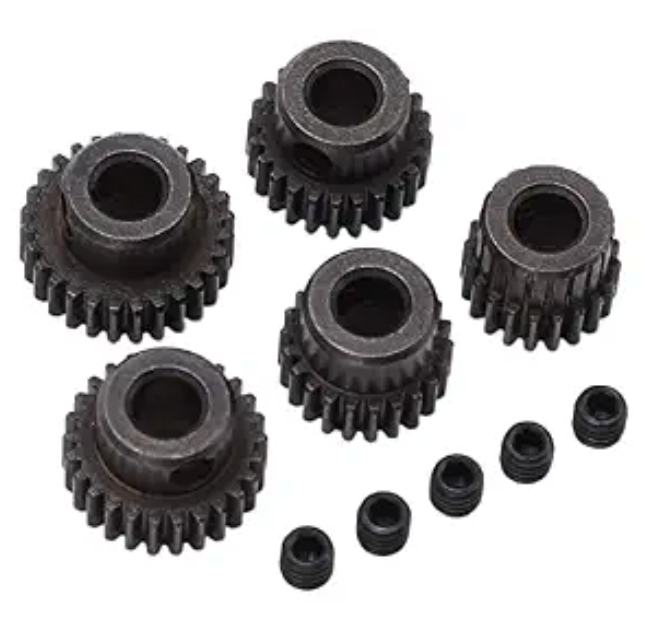
The macroscopic fracture appearance of the pinion gear showed distinct radial marks. By tracing the radial pattern backward, I located the crack origin at the tooth root region of the pinion gear. The crack propagated from this origin until final fracture occurred. The fracture surface also indicated that the pinion gear had experienced a certain amount of torsional stress during service. The fracture surface had a silver-gray metallic luster, no obvious plastic deformation, and small reflective facets when rotated under light. These features are characteristic of a macroscopically brittle fracture. For a pinion gear, such a brittle appearance is significant because it suggests that the material did not undergo sufficient plastic deformation before final separation.
The crack origin at the tooth root is also consistent with the stress state of a meshing pinion gear. The tooth root is a region of high bending stress and stress concentration. When the root fillet is sharp, when machining marks remain, or when the case depth is insufficient, the local stress can exceed the local strength of the pinion gear. Under repeated torsional and bending loads, a small crack can initiate and then propagate rapidly through the section.
Fracture Surface Morphology of the Pinion Gear
I examined the crack-origin region, the fibrous zone, the final fracture zone, and the tooth-groove region of the pinion gear using scanning electron microscopy. The fracture surface at the tooth root was not a smooth plane. Small wavy ledges were present on both sides of the tooth root. At different positions along the tooth root, I did not observe obvious wear marks, pre-existing cracks, or abnormal inclusion defects. The fibrous zone and the final fracture zone exhibited typical transgranular fracture and quasi-cleavage morphology. This confirmed that the pinion gear failed by a brittle fracture mechanism rather than by a ductile overload mechanism.
The tooth-groove region of the crack-origin area showed multiple small cracks. The number of longitudinal cracks was clearly greater than the number of transverse cracks. The tooth-groove surface showed slight wear marks, but no other machining痕迹 or abnormal inclusion defects were observed. These observations are important because they indicate that the pinion gear root and groove regions had already sustained local damage before final fracture. The longitudinal cracks likely acted as preferential paths for crack initiation and early propagation under torsional loading.
| Fracture Feature | Observation in the Pinion Gear | Interpretation |
|---|---|---|
| Macroscopic pattern | Radial marks pointing back to the tooth root | Crack origin at the pinion gear root |
| Surface luster | Silver-gray metallic luster | Brittle fracture appearance |
| Plastic deformation | No obvious deformation | Limited plastic accommodation before fracture |
| Light reflection | Small reflective facets | Cleavage-like or quasi-cleavage features |
| Crack-origin detail | Wavy ledges at the tooth root | Local stress concentration and crack initiation |
| Fibrous and final zones | Transgranular and quasi-cleavage morphology | Brittle fracture mode |
| Tooth groove | Multiple longitudinal and transverse microcracks | Local damage before final fracture |
Macroscopic Structure of the Pinion Gear
I sectioned the fracture region and prepared a low-magnification specimen for macroscopic structure inspection. After acid etching, the pinion gear showed a clear hardened-layer zone, a transition zone, and a matrix zone. I did not observe obvious segregation, cracks, shrinkage cavities, or other macroscopic metallurgical defects. The macroscopic structure was rated according to the relevant structural steel defect rating standard. The center porosity was rated 1.5, general porosity was rated 0.5, and center segregation was rated 0.0. These values were within the standard requirement, which generally permits a rating not exceeding 2.0. Therefore, the macroscopic structure of the pinion gear did not reveal a gross metallurgical defect that could alone explain the fracture.
| Macroscopic Feature | Observation in the Pinion Gear | Rating or Requirement | Assessment |
|---|---|---|---|
| Hardened-layer zone | Clearly visible | Expected after carburizing | Present |
| Transition zone | Clearly visible | Expected hardness gradient | Present |
| Matrix zone | Clearly visible | Core structure | Present |
| Segregation | Not obvious | No harmful segregation | Acceptable |
| Cracks | Not obvious | No macroscopic cracks | Acceptable |
| Shrinkage cavity | Not obvious | No shrinkage defect | Acceptable |
| Center porosity | 1.5 | Not more than 2.0 | Acceptable |
| General porosity | 0.5 | Not more than 2.0 | Acceptable |
| Center segregation | 0.0 | Not more than 2.0 | Acceptable |
Microstructure of the Pinion Gear
I prepared metallographic specimens from the cross section of the pinion gear and observed the case zone, transition zone, and core zone of the failed tooth. The case zone consisted of fine acicular martensite and a small amount of retained austenite. The transition zone consisted mainly of lamellar martensite. The core microstructure consisted mainly of a large amount of free ferrite and lath martensite. This core microstructure is a critical finding because lath martensite has lower hardness than acicular martensite. When the core of a pinion gear contains excessive free ferrite and lath martensite, the load-bearing capacity of the core is reduced. Under torsional and bending loads, the pinion gear core cannot provide sufficient support to the hardened case, and the tooth root becomes vulnerable to crack initiation and rapid propagation.
| Region of the Pinion Gear | Observed Microstructure | Effect on Performance |
|---|---|---|
| Case zone | Fine acicular martensite and small amounts of retained austenite | Provides wear resistance and contact fatigue resistance |
| Transition zone | Lamellar martensite | Controls the hardness gradient from case to core |
| Core zone | Large amount of free ferrite and lath martensite | Lower hardness and lower load-bearing capacity |
The presence of free ferrite in the core of the pinion gear is particularly unfavorable. Ferrite is soft and has low strength. When free ferrite forms a continuous or semi-continuous network, it can provide an easy path for plastic deformation and crack initiation. Lath martensite, although harder than ferrite, is still softer than acicular martensite and does not provide the same resistance to deformation. Therefore, the core microstructure of the pinion gear was not optimal for a component required to withstand torsional and bending loads.
The relationship between hardness and strength in martensitic steels is often approximated by a proportional relationship:
$$
\sigma_y \approx 3.0 HV
$$
where \(\sigma_y\) is the yield strength in MPa and \(HV\) is the Vickers hardness. This relationship is only approximate, but it illustrates why the low core hardness of the pinion gear corresponds to lower load-bearing capacity. If the core hardness is below the design requirement, the pinion gear cannot resist the applied bending and torsional stresses as intended.
Hardened-Layer Depth and Hardness Measurement of the Pinion Gear
I measured the hardened-layer depth at the root and the middle of the tooth top of the failed pinion gear, as well as at a normal tooth for comparison. The measurements followed the microhardness method specified in GB/T 9450-2005. The hardened-layer depth of the failed tooth root was 0.646 mm, the failed tooth top was 0.747 mm, and the second failed tooth root was 0.687 mm. The normal tooth showed a hardened-layer depth of 0.831 mm. All these values were below the required range of 1.2–1.4 mm. This is a major finding because insufficient case depth reduces the load-bearing capacity of the pinion gear and increases the risk of tooth-root fracture.
| Measurement Location | Measured Hardened-Layer Depth (mm) | Specified Range (mm) | Assessment |
|---|---|---|---|
| Failed tooth root 1 | 0.646 | 1.2–1.4 | Below requirement |
| Failed tooth top middle | 0.747 | 1.2–1.4 | Below requirement |
| Failed tooth root 2 | 0.687 | 1.2–1.4 | Below requirement |
| Normal tooth top middle | 0.831 | 1.2–1.4 | Below requirement |
I also measured the core hardness and tooth-surface hardness of the pinion gear. The core hardness values were 237 HV, 245 HV, and 223 HV. The specified core hardness range was 38–45 HRC, corresponding approximately to 370–450 HV. The tooth-surface hardness values were 698 HV, 703 HV, and 691 HV. The specified tooth-surface hardness range was 56–62 HRC, corresponding approximately to 620–760 HV. Although the tooth-surface hardness was within or close to the specified range in some readings, the core hardness was clearly below the required value. This combination of insufficient case depth and low core hardness significantly reduced the load-bearing capacity of the pinion gear.
| Hardness Location | Measured Value | Specified Value | Assessment for the Pinion Gear |
|---|---|---|---|
| Core | 237 HV, 245 HV, 223 HV | 38–45 HRC / 370–450 HV | Below requirement |
| Tooth surface | 698 HV, 703 HV, 691 HV | 56–62 HRC / 620–760 HV | Partially acceptable but not uniformly verified |
The hardness profile of a properly carburized pinion gear should decrease gradually from the surface to the core. An ideal profile provides high surface hardness for wear resistance and contact fatigue resistance, while maintaining sufficient core hardness and toughness for load-bearing capacity. In the failed pinion gear, the case depth was insufficient and the core hardness was low. Therefore, the pinion gear could not develop the intended compressive residual stress and hardness gradient. Under torsional loading, the tooth root experienced a combination of bending stress and shear stress. The low-strength core could not support the case, and the crack propagated in a brittle manner.
Stress Analysis and Fracture Mechanics Considerations for the Pinion Gear
The fracture of the pinion gear can be understood in terms of stress concentration, fracture mechanics, and fatigue crack growth. The nominal bending stress at the tooth root can be approximated by:
$$
\sigma_{nom}=\frac{F_t}{b m_n}
$$
where \(F_t\) is the tangential force, \(b\) is the face width, and \(m_n\) is the normal module. The actual stress at the tooth root is higher than the nominal stress because of the root fillet geometry, machining marks, and load distribution. The stress concentration factor can be expressed as:
$$
K_t=1+q(\alpha-1)
$$
where \(q\) is the notch sensitivity and \(\alpha\) is the geometric stress concentration factor. A sharp root fillet increases \(\alpha\), which in turn increases \(K_t\). For the pinion gear, the crack origin was located at the tooth root, which is consistent with a high \(K_t\) region.
Once a crack initiates, the stress intensity factor at the crack tip can be written as:
$$
K_I=Y\sigma\sqrt{\pi a}
$$
where \(K_I\) is the mode I stress intensity factor, \(Y\) is a geometry factor, \(\sigma\) is the applied stress, and \(a\) is the crack length. Brittle fracture occurs when \(K_I\) reaches the fracture toughness \(K_{IC}\) of the material. The critical crack size can be estimated by:
$$
a_c=\frac{1}{\pi}\left(\frac{K_{IC}}{Y\sigma}\right)^2
$$
If the local material toughness is low because of a brittle microstructure, or if the local stress is high because of stress concentration, the critical crack size becomes small. In the pinion gear, the combination of a brittle fracture mode, a low-hardness core, insufficient case depth, and a tooth-root stress concentration reduced the critical crack size and promoted rapid fracture.
For fatigue loading, the alternating stress and mean stress can be defined as:
$$
\sigma_a=\frac{\sigma_{max}-\sigma_{min}}{2}
$$
$$
\sigma_m=\frac{\sigma_{max}+\sigma_{min}}{2}
$$
$$
R=\frac{\sigma_{min}}{\sigma_{max}}
$$
The fatigue life can be approximated by a Basquin-type relationship:
$$
N_f=\left(\frac{\sigma_a}{\sigma_f’}\right)^{1/b}
$$
where \(N_f\) is the number of cycles to failure, \(\sigma_f’\) is the fatigue strength coefficient, and \(b\) is the fatigue strength exponent. A pinion gear with low core hardness and insufficient case depth will have a lower effective fatigue strength, which reduces \(N_f\) and increases the probability of early fracture.
Discussion of the Pinion Gear Fracture Mechanism
The failure of the pinion gear was not caused by a single factor. The chemical composition was acceptable, and no gross metallurgical defects such as severe segregation, cracks, or shrinkage cavities were found. However, the heat-treatment quality and microstructure were inadequate. The hardened-layer depth was below the required value, the core hardness was below the required value, and the core microstructure contained excessive free ferrite and lath martensite. These conditions reduced the load-bearing capacity of the pinion gear and made the tooth root vulnerable to crack initiation under torsional and bending loads.
The fracture surface showed transgranular fracture and quasi-cleavage features, which are typical of brittle fracture. The crack origin was at the tooth root, where stress concentration is highest. The presence of multiple longitudinal microcracks in the tooth groove indicates that local damage occurred before final fracture. Once the crack initiated, the low-toughness core and insufficient case depth allowed the crack to propagate rapidly. The final fracture occurred when the remaining section could no longer support the applied load.
| Contributing Factor | Observation in the Pinion Gear | Effect on Fracture |
|---|---|---|
| Chemical composition | Within the 20CrMnTi specification | Not a primary cause |
| Macroscopic defects | No obvious segregation, cracks, or shrinkage cavities | Not a primary cause |
| Case depth | 0.646–0.831 mm, below 1.2–1.4 mm | Reduced load-bearing capacity and residual stress |
| Core hardness | 223–245 HV, below 370–450 HV | Reduced support for the case and lower strength |
| Tooth-surface hardness | 691–703 HV, near or within part of the requirement | Insufficient to compensate for low core strength |
| Core microstructure | Free ferrite and lath martensite | Lower hardness and lower relative load-bearing capacity |
| Tooth-root geometry | Crack origin at the root; possible fillet discontinuity | Stress concentration and crack initiation |
| Fracture mode | Transgranular and quasi-cleavage | Brittle fracture with little plastic deformation |
The pinion gear failure can therefore be described as a brittle fracture driven by insufficient case depth, low core hardness, unfavorable core microstructure, and tooth-root stress concentration. The low core hardness is especially important because the core must support the hardened case and carry bending and torsional loads. When the core contains free ferrite and lath martensite, its yield strength is lower than that of a properly hardened core. The pinion gear then deforms locally, the case experiences additional tensile stress, and the crack initiates at the root.
Hardness Gradient and Load-Bearing Capacity of the Pinion Gear
The hardness gradient of a carburized pinion gear is a critical design parameter. The case depth must be sufficient to resist contact fatigue, wear, and bending stress. The core hardness must be sufficient to support the case and resist torsional deformation. The hardness gradient can be represented schematically as a function of depth:
$$
HV(x)=HV_{core}+(HV_{surface}-HV_{core})\exp\left(-\frac{x}{\lambda}\right)
$$
where \(x\) is the depth below the surface, \(HV_{surface}\) is the surface hardness, \(HV_{core}\) is the core hardness, and \(\lambda\) is a characteristic decay length related to the carburizing and quenching process. For the failed pinion gear, the measured case depth was too small and the core hardness was too low. Therefore, the hardness gradient did not provide the required support. The effective load-bearing capacity of the pinion gear can be expressed qualitatively as:
$$
F_{load}\propto HV_{surface}\,CHD+HV_{core}\,d_{core}
$$
where \(CHD\) is the case-hardened depth and \(d_{core}\) is the effective core thickness. If either \(CHD\) or \(HV_{core}\) is below the design value, the load-bearing capacity of the pinion gear decreases. In this failure, both \(CHD\) and \(HV_{core}\) were below the specification, which explains the brittle fracture under service loading.
Metallurgical Factors in the Pinion Gear Core
The core microstructure of the pinion gear consisted mainly of free ferrite and lath martensite. Free ferrite forms when the cooling rate during quenching is insufficient or when the austenitizing temperature and time are not adequate to dissolve carbon and alloying elements. Lath martensite forms in low-carbon or low-alloy regions and has a lower hardness than acicular martensite. The presence of free ferrite and lath martensite indicates that the core did not transform completely into a high-hardness martensitic structure. This condition reduces the yield strength and fatigue strength of the pinion gear core.
The volume fraction of free ferrite can be estimated from metallographic image analysis:
$$
f_f=\frac{A_f}{A_{total}}
$$
where \(f_f\) is the area fraction of free ferrite, \(A_f\) is the ferrite area, and \(A_{total}\) is the total measured area. A high \(f_f\) value is undesirable in a pinion gear core because ferrite is soft and provides an easy path for crack initiation. The presence of lath martensite can be described by its packet size and block width. Finer martensitic structures generally provide higher strength and toughness. In the failed pinion gear, the core did not exhibit the fine acicular martensitic structure that would provide optimal load-bearing capacity.
| Core Constituent | Expected Effect | Observed Effect in the Pinion Gear |
|---|---|---|
| Free ferrite | Soft, low strength, crack initiation sites | Present in large amounts; reduced core strength |
| Lath martensite | Moderate hardness, lower than acicular martensite | Dominated part of the core; insufficient hardness |
| Acicular martensite | High hardness and good load-bearing capacity | Present mainly in the case, not in the core |
| Retained austenite | May improve toughness but reduce hardness if excessive | Small amount in the case |
Heat-Treatment Process and Case Depth Control for the Pinion Gear
The measured case depth of the pinion gear was significantly below the required range. This indicates that the carburizing process was not properly controlled. Possible causes include insufficient carburizing time, insufficient carburizing temperature, low carbon potential, inadequate furnace atmosphere control, or improper loading of the pinion gear in the furnace. The case depth produced by carburizing can be estimated by:
$$
CHD=k\sqrt{t}
$$
where \(CHD\) is the case-hardened depth, \(k\) is a temperature-dependent coefficient, and \(t\) is the carburizing time. If the actual time or temperature is lower than the designed value, the case depth will be insufficient. A more complete expression includes the diffusion coefficient:
$$
CHD=K\sqrt{Dt}
$$
where \(K\) is a constant related to the surface carbon concentration and the critical hardness. Because \(D\) depends exponentially on temperature, a small decrease in carburizing temperature can significantly reduce the case depth. The low case depth of the pinion gear is therefore a strong indicator of a heat-treatment deviation.
| Process Variable | Expected Role | Possible Deviation in the Pinion Gear |
|---|---|---|
| Carburizing temperature | Controls carbon diffusion rate | Too low or non-uniform |
| Carburizing time | Controls total diffusion distance | Too short |
| Carbon potential | Controls surface carbon concentration | Too low or poorly controlled |
| Quenching rate | Controls martensite formation and core hardness | Too slow, producing ferrite and lath martensite |
| Tempering | Controls toughness and residual stress | Possibly not optimized |
| Furnace loading | Controls uniform atmosphere exposure | Poor loading may cause non-uniform case depth |
Fracture Surface and Crack Path Interpretation for the Pinion Gear
The fracture surface of the pinion gear showed radial marks converging toward the tooth root. This pattern is consistent with a single crack origin. The crack propagated from the root toward the tooth body and eventually caused final fracture. The presence of transgranular and quasi-cleavage features indicates that the crack path was not strongly influenced by grain boundaries or inclusions. Instead, the crack propagated through the grains in a brittle manner. This type of fracture is common when the material has low toughness, high hardness, or insufficient core support.
The quasi-cleavage morphology can be described in terms of the local fracture stress:
$$
\sigma_f=\sqrt{\frac{2E\gamma}{\pi a}}
$$
where \(\sigma_f\) is the fracture stress, \(E\) is Young’s modulus, \(\gamma\) is the surface energy, and \(a\) is the crack length. When the local stress exceeds \(\sigma_f\), cleavage-like fracture occurs. In the pinion gear, the combination of high local stress at the tooth root and low local toughness in the core promoted quasi-cleavage fracture.
Root Cause Summary for the Pinion Gear
Based on my analysis, the root cause of the pinion gear fracture was inadequate heat treatment, specifically insufficient case depth and low core hardness. The core microstructure contained free ferrite and lath martensite, which reduced the load-bearing capacity of the pinion gear. The tooth-root region acted as the crack initiation site because of stress concentration. Under service loading, the combination of torsional stress, bending stress, and contact stress exceeded the local strength of the pinion gear. The crack propagated in a brittle transgranular and quasi-cleavage mode, leading to final fracture.
| Root Cause Category | Specific Finding | Contribution to Pinion Gear Fracture |
|---|---|---|
| Material chemistry | Within 20CrMnTi specification | Not the primary cause |
| Macroscopic defects | No severe segregation, cracks, or shrinkage | Not the primary cause |
| Case depth | Below 1.2–1.4 mm requirement | Reduced wear and bending resistance |
| Core hardness | Below 370–450 HV requirement | Reduced support for the case |
| Core microstructure | Free ferrite and lath martensite | Lower strength and toughness |
| Stress concentration | Tooth-root origin | Promoted crack initiation |
| Fracture mode | Transgranular and quasi-cleavage | Brittle fracture with little deformation |
Corrective Actions and Preventive Measures for the Pinion Gear
To prevent recurrence of pinion gear fracture, I recommend improvements in design, heat treatment, inspection, and service monitoring. The tooth-root fillet should be optimized to reduce stress concentration. Sharp notches, machining marks, and abrupt section changes should be avoided. The carburizing process should be controlled to achieve the specified case depth of 1.2–1.4 mm. The core hardness should be maintained within the required range of 38–45 HRC. The quenching process should be optimized to produce a fine martensitic core with minimal free ferrite and lath martensite. Tempering should be controlled to provide the required toughness and residual stress distribution.
| Corrective Action | Target | Expected Benefit for the Pinion Gear |
|---|---|---|
| Optimize root fillet | Reduce stress concentration | Lower crack initiation risk at the tooth root |
| Increase effective carburizing time or temperature | Achieve 1.2–1.4 mm case depth | Improve bending and contact fatigue resistance |
| Improve carbon potential control | Obtain a proper carbon profile | Uniform surface hardness and case depth |
| Increase quenching rate | Avoid free ferrite and lath martensite | Higher core hardness and load-bearing capacity |
| Optimize tempering | Balance hardness and toughness | Reduce brittle fracture susceptibility |
| Shot peening | Introduce compressive residual stress | Improve fatigue strength of the pinion gear |
| Hardness and case-depth inspection | Verify every production lot | Prevent nonconforming pinion gears from entering service |
| Service load review | Confirm torsional and bending loads | Ensure the pinion gear operates within design limits |
I also recommend that the pinion gear production process include statistical process control for carburizing temperature, time, carbon potential, and quench rate. Microhardness profiles should be measured on representative pinion gears from each batch. The case depth should be measured at multiple positions, including the tooth root and tooth top. The core hardness should be measured at the center of the tooth or at a defined depth below the case. Metallographic examination should quantify free ferrite and lath martensite in the core. If free ferrite exceeds the allowable limit, the heat-treatment cycle should be adjusted.
Engineering Assessment of the Pinion Gear Fracture
From an engineering perspective, the pinion gear failed because the actual material condition did not match the design intent. The design intended a carburized pinion gear with a deep enough case to resist bending and contact fatigue and a hard enough core to support the case. The actual pinion gear had a shallow case, a soft core, and a microstructure containing free ferrite and lath martensite. These conditions shifted the failure mode from a gradual fatigue process to a rapid brittle fracture. The tooth-root origin and the transgranular quasi-cleavage features confirm that the crack initiated at a stress concentration and propagated without significant plastic deformation.
The fracture mechanics assessment supports this conclusion. The stress intensity factor at the crack tip increased as the crack grew. Because the core toughness was low, the critical crack size was small. Once the crack reached the critical size, unstable fracture occurred. The radial marks on the fracture surface are consistent with rapid crack propagation from a single origin. The absence of obvious plastic deformation on the macroscopic fracture surface further confirms the brittle nature of the pinion gear fracture.
Comparison of Failed and Normal Pinion Gear Conditions
To clarify the difference between the failed pinion gear and an acceptable condition, I summarized the key parameters in Table 9. The failed pinion gear had a case depth of 0.646–0.747 mm, while the normal tooth had a case depth of 0.831 mm. All values were below the required 1.2–1.4 mm. The core hardness of the failed pinion gear was 223–245 HV, while the required core hardness was 370–450 HV. The tooth-surface hardness was 691–703 HV, which was close to the lower part of the required range but could not compensate for the low core hardness and shallow case depth.
| Parameter | Failed Pinion Gear | Normal or Required Condition | Gap |
|---|---|---|---|
| Case depth | 0.646–0.747 mm | 1.2–1.4 mm | Substantially below requirement |
| Core hardness | 223–245 HV | 370–450 HV | Far below requirement |
| Tooth-surface hardness | 691–703 HV | 620–760 HV | Partially within range but not sufficient alone |
| Core microstructure | Free ferrite and lath martensite | Fine martensite with limited ferrite | Unfavorable for load bearing |
| Fracture mode | Transgranular and quasi-cleavage | Ductile or fatigue-resistant behavior | Brittle fracture |
Summary of Key Equations for Pinion Gear Failure Analysis
The following equations summarize the main analytical relationships used in my assessment of the pinion gear. They are presented in Table 10 for clarity. These equations are not intended to replace detailed finite element analysis or fracture mechanics testing, but they provide a useful framework for understanding how case depth, core hardness, stress concentration, and crack growth interact in a pinion gear failure.
| Equation Description | Expression | Relevance to the Pinion Gear |
|---|---|---|
| Carbon diffusion profile | $$C(x,t)=C_s-(C_s-C_0)\operatorname{erf}\left(\frac{x}{2\sqrt{Dt}}\right)$$ | Controls case depth and carbon gradient |
| Diffusion coefficient | $$D=D_0\exp\left(-\frac{Q_d}{RT}\right)$$ | Temperature dependence of carburizing |
| Case depth approximation | $$CHD=k\sqrt{t}$$ | Relates carburizing time to case depth |
| Nominal bending stress | $$\sigma_{nom}=\frac{F_t}{b m_n}$$ | Tooth-root bending load |
| Stress concentration factor | $$K_t=1+q(\alpha-1)$$ | Effect of root fillet and notch sensitivity |
| Stress intensity factor | $$K_I=Y\sigma\sqrt{\pi a}$$ | Crack-tip driving force |
| Critical crack size | $$a_c=\frac{1}{\pi}\left(\frac{K_{IC}}{Y\sigma}\right)^2$$ | Brittle fracture condition |
| Alternating stress | $$\sigma_a=\frac{\sigma_{max}-\sigma_{min}}{2}$$ | Fatigue loading of the pinion gear |
| Mean stress | $$\sigma_m=\frac{\sigma_{max}+\sigma_{min}}{2}$$ | Mean load effect |
| Stress ratio | $$R=\frac{\sigma_{min}}{\sigma_{max}}$$ | Cyclic loading parameter |
| Fatigue life approximation | $$N_f=\left(\frac{\sigma_a}{\sigma_f’}\right)^{1/b}$$ | Estimated cycles to failure |
| Hardness-strength relation | $$\sigma_y\approx 3.0 HV$$ | Core hardness and load-bearing capacity |
| Fracture stress | $$\sigma_f=\sqrt{\frac{2E\gamma}{\pi a}}$$ | Local brittle fracture condition |
| Ferrite area fraction | $$f_f=\frac{A_f}{A_{total}}$$ | Quantifies free ferrite in the core |
Conclusions of the Pinion Gear Failure Analysis
1. The pinion gear fracture was a typical brittle fracture. The crack origin was located at the tooth root of the pinion gear, where stress concentration is high. Under service loading, this region was prone to crack initiation and rapid propagation.
2. The fracture mode of the pinion gear was transgranular fracture combined with quasi-cleavage brittle fracture. The fracture surface showed radial marks, a silver-gray metallic luster, no obvious plastic deformation, and small reflective facets. These features confirm a brittle fracture mechanism rather than a ductile overload mechanism.
3. The chemical composition of the pinion gear was consistent with the 20CrMnTi specification. No abnormal alloying element or harmful impurity content was found that could alone explain the fracture. The macroscopic structure also showed no severe segregation, cracks, shrinkage cavities, or other gross metallurgical defects.
4. The hardened-layer depth of the pinion gear was below the technical requirement. The measured values at the failed tooth root and tooth top were 0.646–0.747 mm, while the required range was 1.2–1.4 mm. The normal tooth also showed only 0.831 mm, which was still below the requirement.
5. The core hardness of the pinion gear was below the technical requirement. The measured core hardness was 223–245 HV, while the required range was 370–450 HV. The tooth-surface hardness was 691–703 HV, which was near or within part of the required range, but it could not compensate for the low core hardness and shallow case depth.
6. The core microstructure of the pinion gear consisted mainly of free ferrite and lath martensite. Compared with acicular martensite, lath martensite has lower hardness and lower relative load-bearing capacity. The presence of free ferrite further reduced the strength of the core. As a result, the pinion gear core could not provide sufficient support to the case under torsional and bending loads.
7. The pinion gear fracture was caused by the combined effects of insufficient case depth, low core hardness, unfavorable core microstructure, and tooth-root stress concentration. These factors reduced the load-bearing capacity of the pinion gear and promoted brittle fracture under service loading.
8. To prevent future pinion gear failures, the tooth-root fillet should be optimized to reduce stress concentration. The carburizing and quenching processes should be improved to achieve the specified case depth and core hardness. The core microstructure should be controlled to avoid excessive free ferrite and lath martensite. Hardness and case-depth inspections should be performed on every production lot. Shot peening and other surface treatments can also be considered to introduce compressive residual stresses and improve fatigue resistance.
In my assessment, the failed pinion gear did not fail because of a single material defect. It failed because the actual heat-treatment condition did not meet the design requirements. The pinion gear was expected to carry torsional and bending loads with a deep carburized case and a strong core. Instead, the pinion gear had a shallow case, a soft core, and a brittle fracture mode. Correcting the heat-treatment process and verifying the case depth, core hardness, and microstructure will significantly improve the reliability of future pinion gears.