
In this study, I investigate the fault diagnosis of hydraulic mechanical drive pinion gears by using a support vector machine (SVM) framework. Hydraulic mechanical systems are widely used in industrial transmission, and their reliability depends heavily on the health condition of pinion gears. More than half of the faults in such systems are caused by the gearbox, and the most common failure modes of pinion gears include local faults, pitting, wear, and broken teeth. When a hydraulic mechanical drive operates in a complex environment, the pinion gears are often enclosed and run in a sealed state. As a result, abnormal conditions of the pinion gears are difficult to detect in time, which can lead to delayed production and transportation, low production efficiency, and even serious accidents with losses and casualties. Therefore, I aim to monitor the operating state of hydraulic mechanical drive pinion gears and to develop an effective fault diagnosis method.
To address the problems of poor accuracy and low reliability in the fault diagnosis of hydraulic mechanical drive pinion gears, I propose a diagnosis method based on SVM. The method includes vibration signal acquisition, low-rank signal separation, stacked denoising autoencoder (SDAE) feature extraction, and SVM classification. I use low-rank constraints to separate the vibration source signals of the hydraulic mechanical drive gearbox, design constraint conditions for the fault signals of pinion gears, and classify the pinion gear faults. Based on the classification results, I employ an SDAE model to extract fault features from the hydraulic mechanical drive pinion gears. The extracted features are then input into an SVM for training, and the final output is the optimal diagnosis result. Experimental results show that the classification error rate of my method does not exceed 3.5%, which verifies its high feasibility.
Vibration Signal Acquisition for Hydraulic Mechanical Drive Pinion Gears
I treat the fault location of the rotating machinery as the fault type and collect the original data from the fault area. I use vibration sensors and torque sensors to obtain data groups from the rotating machinery, thereby acquiring the original signal data set of the hydraulic mechanical drive pinion gears. The acquisition result is defined as follows:
$$
\begin{aligned}
& y_i \in \{y_1, y_2, y_3\}, \quad i = 1, 2, \ldots, 3l \\
& D = \{D_1 \cup D_2\} \\
& D_1 = \{(x_i, y_i)\}, \quad i = 1, 2, \ldots, 3l \\
& D_2 = \{(x’_i, y_i)\}, \quad i = 1, 2, \ldots, 3l
\end{aligned}
$$
Here, \(y_i\) is the fault type, and \(y_i \in \{y_1, y_2, y_3\}\), where \(y_1\) represents crack fault, \(y_2\) represents missing tooth fault, and \(y_3\) represents broken tooth fault. \(x_i\) is the measured output of the vibration sensor, \(x’_i\) is the measured output of the torque sensor, and \(D\) is the acquired original signal data set. These signals provide the foundation for diagnosing faults in hydraulic mechanical drive pinion gears.
Noise Signal Separation for Hydraulic Mechanical Drive Pinion Gears
For unknown signals with sparsity in an uncertain linear system, a unique and stable solution can be obtained under undersampling conditions. When the columns or rows of the signal matrix of hydraulic mechanical drive pinion gears have similarity, the rank of the matrix is sparse. By reducing the rank value, the complexity of the known signal can be reduced. The low-rank constraint used in this study is a low-rank algorithm. When the gearbox of rotating machinery operates under normal conditions, the signals generated by the rotating machinery or inside the machinery usually have low-rank properties. This low-rank property can constrain the separation features of vibration signals and overcome the uncertainty problems of existing separation methods.
First, I collect the original signals of the hydraulic mechanical drive pinion gears and verify whether the noise data of the original vibration signals of the pinion gears satisfy a Gaussian distribution. Then I construct a vibration source signal separation model under low-rank constraints. The construction result is as follows:
$$
\begin{aligned}
& \arg\min_{L,N} \ \operatorname{rank}(L) + \beta \times \operatorname{kur}(N) \\
& \text{s.t.} \ D = L + N
\end{aligned}
$$
In this expression, \(D\) is the observation matrix, \(N\) is the noise term, \(L\) is the low-rank matrix, \(\operatorname{rank}\) is the rank function, \(\beta\) is a compromise factor, and \(\operatorname{kur}(N)\) is the kurtosis function.
Because the above equation is a complex polynomial, I use convex relaxation to transform it. The transformed problem is defined as follows:
$$
\begin{aligned}
& \arg\min_{L,N} \ \|L\|_* + \beta \times \operatorname{kur}(N) \\
& \text{s.t.} \ D = L + N
\end{aligned}
$$
Here, \(\|L\|_*\) is the nuclear norm.
In order to separate multiple vibration sources of the hydraulic mechanical drive pinion gears under low-rank constraints, I modify the constructed model and form a separation model with multiple low-rank constraints:
$$
\begin{aligned}
& \arg\min_{L,N} \sum_{i=1}^{n} \lambda_i \|L_i\|_* + \beta \times \operatorname{kur}(N) \\
& \text{s.t.} \ x = \sum_{i=1}^{n} l_i + N
\end{aligned}
$$
where \(l_i\) is an ordered array, \(n\) is the number of sources to be separated, and \(\lambda_i\) is the weight of the low-rank matrix.
I set a group of vibration signals of hydraulic mechanical drive pinion gears with length \(m\), denoted as \(x(t)\), and obtain them using a low-rank matrix \(L_i\). I let \(w\) represent a blocking operator. Through \(w\), I can transform \(x(t)\) into a two-dimensional matrix \(L_i\).
Based on the characteristic frequencies generated by the pinion gears at different speeds, I analyze the design parameters of the pinion gears, such as module, number of teeth, and pitch circle diameter. According to the application scenario and requirements of the hydraulic mechanical system, I design the low-rank constraint condition for the fault signals of the pinion gears as follows:
$$
\frac{p_i \lambda_i f_s}{f_{\text{source},i}} > o_i
$$
where \(o_i\) is the array length, \(p_i\) is the number of arrays, \(f_s\) is the sampling frequency, and \(f_{\text{source},i}\) is the characteristic frequency of the vibration source signal. Combined with the above constraint, I solve the separation model and complete the classification of the fault signals of the pinion gears, so as to confirm different types of faults, such as tooth surface wear, backlash variation, and chatter. Different fault types have different signal characteristics in the vibration spectrum and characteristic frequency. Through classification, I can identify fault types more accurately.
According to the calculation results, I use \(w\) to block the signals of the hydraulic mechanical drive pinion gears under low-rank constraints. The blocking operator calculation is summarized in the following table.
| Symbol | Meaning | Function in the separation of pinion gear signals |
|---|---|---|
| \(w\) | Blocking operator | Transforms the one-dimensional vibration signal into a two-dimensional low-rank matrix |
| \(L_i\) | Low-rank matrix of the \(i\)-th source | Represents the low-rank component of the pinion gear vibration source |
| \(N\) | Noise term | Captures the sparse noise and interference in the pinion gear signal |
| \(\lambda_i\) | Low-rank matrix weight | Balances the contribution of each pinion gear vibration source |
| \(f_{\text{source},i}\) | Characteristic frequency of the vibration source | Provides the frequency-domain constraint for pinion gear fault separation |
According to the blocking result, I use the Lagrange multiplier method to solve the convex optimization problem of the rotating machinery and solve the vibration source signals of the blocked hydraulic mechanical drive pinion gears. The enhanced Lagrange function is established as follows:
$$
L_a(l_i, N, Y, \mu_k) = \sum_{i=1}^{n} \lambda_i \|L_i\|_* + \beta \operatorname{kur}(N) + \left\langle Y, x – \sum_{k=1}^{K} l_i – N \right\rangle
$$
where \(L_a\) is the enhanced Lagrange function, \(Y\) is the Lagrange multiplier, \(\mu_k\) is the iteration step size, and \(\langle \cdot, \cdot \rangle\) denotes the inner product operation.
Based on the construction result, I use the alternating direction method of multipliers to optimize the minimum nuclear norm of each low-rank matrix and to iterate the minimum kurtosis of the noise term. The iteration process is as follows:
$$
l_{i,k+1}^* = \arg\min_{l_i} \left\{ \frac{\lambda_i}{\mu_k} \|L_i\|_* + \frac{1}{2} \left\| x – \sum_{j=1}^{i-1} l_{j,k+1} – l_i – \sum_{j=i+1}^{n} l_{j,k} – N_k \right\|^2 + \frac{1}{2} \left\| x – \sum_{q=1}^{Q} l_{q,k} – N + \frac{1}{\mu_k} \right\|^2 \right\}
$$
where \(j\) is a coefficient. I use singular value decomposition and soft thresholding to solve the above equation, which is defined as follows:
$$
\begin{aligned}
& [U_i, S_i, V_i] = \operatorname{SVD}(w(T_{i,k}, o_i, p_i)) \\
& l_{i,k+1} = w\left( U_i S_{\lambda_i / \mu_k}[S_i] V_i^T \right)^{-1}
\end{aligned}
$$
Here, \(\operatorname{SVD}\) is the singular value decomposition operator, \(S_{\lambda_i / \mu_k}[S_i]\) is the singular value parameter, \(S_{\lambda_i / \mu_k}\) is the soft threshold shrinkage operator, \(w\) is the inverse operation of the blocking operator, \(U_i\) is the singular value, and \(V\) is a random parameter.
According to the solution results, I separate the vibration source signals of the hydraulic mechanical drive pinion gears under low-rank constraints, so that the fault diagnosis results of the pinion gear vibration source signals become better. The separation process is summarized in the following table.
| Step | Operation | Purpose for pinion gears |
|---|---|---|
| 1 | Collect original vibration signals of hydraulic mechanical drive pinion gears | Obtain the observed data matrix \(D\) |
| 2 | Verify noise distribution | Determine whether the pinion gear signal noise satisfies Gaussian distribution |
| 3 | Construct low-rank separation model | Separate multiple vibration sources of pinion gears |
| 4 | Apply convex relaxation and nuclear norm | Transform the rank minimization into a tractable problem for pinion gear signals |
| 5 | Design low-rank constraint condition | Use characteristic frequency to constrain pinion gear fault separation |
| 6 | Solve with alternating direction method of multipliers | Obtain separated source signals of pinion gears |
| 7 | Use singular value decomposition and soft thresholding | Update each low-rank matrix corresponding to pinion gear sources |
Fault Feature Extraction for Hydraulic Mechanical Drive Pinion Gears Using SDAE
The separation of vibration source signals of hydraulic mechanical drive pinion gears under low-rank constraints is of great significance for the fault diagnosis of these pinion gears. Based on the separation results, the classification effect of the hydraulic mechanical drive pinion gears is greatly improved.
After separating the vibration source signals of the hydraulic mechanical drive pinion gears under low-rank constraints, I use a stacked denoising autoencoder (SDAE) model to extract the fault features of the hydraulic mechanical drive pinion gears. Then I input the extraction results into the constructed SVM classifier for training, and the result is the final diagnosis result.
I introduce optimization criteria into the SDAE model to extract more effective fault features of the hydraulic mechanical drive pinion gears.
1) Minimum sparsity. The sparsity of the fault features of hydraulic mechanical drive pinion gears can effectively represent the potential characteristics of the pinion gears and perfectly express the essential fault features of the pinion gears. It is defined as follows:
$$
f_1(S) = \sum_{j=1}^{D} \operatorname{KL}\left( \rho \parallel \hat{\rho}_j \right)
$$
where \(\rho\) is the sparsity parameter, \(\operatorname{KL}(\rho \parallel \hat{\rho}_j)\) is the relative entropy, \(\hat{\rho}_j\) is the average activation, \(j\) is the number of hidden layers, \(f_1(S)\) is the sparsity, and \(D\) is the number of hidden layer nodes. When the value of \(f_1(S)\) is smaller, the sparsity of the extracted fault features of the hydraulic mechanical drive pinion gears is smaller. Therefore, I normalize \(f_1(S)\) so that \(f_1(S) \in [0,1]\).
2) Minimum classification error rate. In order to reduce the fault diagnosis error rate of hydraulic mechanical drive pinion gears, I need to keep the error rate at a minimum. The expression is defined as follows:
$$
f_2(S) = 1 – \frac{s}{M}
$$
where \(s\) is the number of correctly diagnosed samples and \(M\) is the sample size.
Based on the above optimization objectives, I construct the SDAE fault feature extraction model, and its objective function is defined as follows:
$$
\begin{aligned}
& \min F(S) \\
& F(S) = \{f_1(S), f_2(S)\}
\end{aligned}
$$
Based on the construction result, I use this model to extract the fault features of the hydraulic mechanical drive pinion gears under low-rank constraints. The extraction process is as follows.
Input: vibration source signal spectrum \(X\) of the hydraulic mechanical drive pinion gears and label \(y\).
- Set various parameters and determine the population neighbors.
- Calculate the objective function value of the decision vector \(d\) of the rotating machinery and obtain the minimum objective value of the population.
- Select two neighbors from the population, perform crossover operation, and update the population neighbors and the minimum objective value.
- If the maximum number of iterations is reached, stop; otherwise, continue with step 3.
- Obtain multiple optimal MO-SADE models and extract the diverse fault features of the hydraulic mechanical drive pinion gears.
Output: diverse fault features of the hydraulic mechanical drive pinion gears.
| Optimization objective | Expression | Role for pinion gear diagnosis |
|---|---|---|
| Minimum sparsity | \(f_1(S) = \sum_{j=1}^{D} \operatorname{KL}(\rho \parallel \hat{\rho}_j)\) | Ensures that the extracted features reflect the essential fault characteristics of pinion gears |
| Minimum classification error | \(f_2(S) = 1 – s/M\) | Reduces the misdiagnosis rate of pinion gear faults |
| Overall objective | \(F(S) = \{f_1(S), f_2(S)\}\) | Balances sparsity and classification accuracy for pinion gears |
SVM-Based Fault Diagnosis for Hydraulic Mechanical Drive Pinion Gears
I assume that a clean low-rank matrix \(L \in \mathbb{R}^{m \times n}\) is contaminated by a sparse error matrix \(S \in \mathbb{R}^{m \times n}\). Then the fault degradation model of the hydraulic mechanical drive pinion gears is:
$$
D = L + S
$$
where \(D \in \mathbb{R}^{m \times n}\) is the observed data matrix and is known. The low-rank matrix \(L\) and the sparse error matrix \(S\) are both unknown. The final purpose is to recover the low-rank matrix \(L\). This problem formulation proposes a conceptual solution: find the matrix \(L\) that produces the lowest rank for the known data, with the constraint that the error matrix \(S\) is sparse, that is, \(\|S\|_0 \leq k\).
To find the best low-rank matrix, I can minimize the mean square error between the observed matrix and the low-rank matrix:
$$
\min_{L} \|L – D\|_F^2 \quad \text{s.t.} \ \operatorname{rank}(L) = r
$$
where \(\|\cdot\|_F^2\) is the Frobenius norm, \(\operatorname{rank}(L)\) denotes the rank of matrix \(L\), and \(r\) is the expected rank. I input the expected rank \(r\) into the SVM for training to achieve the final diagnosis.
I set the sample set of the hydraulic mechanical drive pinion gears as \((x_i, y_i)\), where \(x_i\) is the class attribute and \(y_i\) is the class label. The SVM maps from a low-dimensional space to a high-dimensional space and obtains the optimal hyperplane:
$$
f(x) = \sum_{i=1}^{n} y_i a_i K(x, x_i) + b
$$
where \(a_i\) is the Lagrange multiplier, \(K(x, x_i)\) is the kernel function, and \(b\) is the bias. The Gaussian radial kernel function is expressed as:
$$
K(x, x_i) = \exp\left( -\frac{(x, x_i)^2}{2\sigma^2} \right)
$$
where \(\sigma\) is the variance, that is, \(g = 1/(2\sigma^2)\), and \(g\) is the kernel function parameter.
According to the above results, I construct the support vector machine and use it to perform fault diagnosis on the hydraulic mechanical drive pinion gears. The diagnosis process is as follows.
- Collect vibration signals of pinion gears under multiple fault conditions.
- Separate the collected results to obtain the vibration source signals of the hydraulic mechanical drive pinion gears under low-rank constraints, thereby improving the fault diagnosis effect.
- Extract fault features of the hydraulic mechanical drive pinion gears and divide them into training samples and test samples.
- Input the training samples into the constructed SVM support vector machine and, after training, achieve fault diagnosis.
Based on the above fault diagnosis process, I realize the fault diagnosis of hydraulic mechanical drive pinion gears under low-rank constraints.
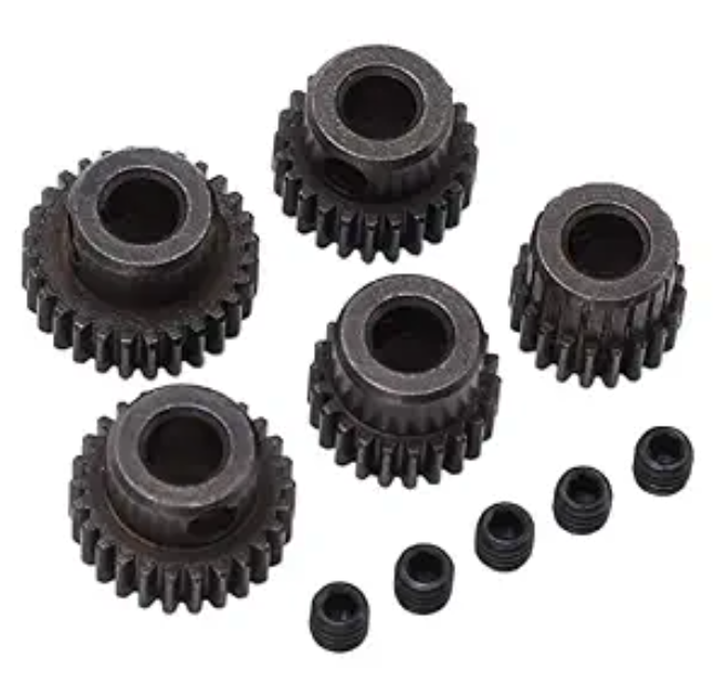
Experimental Environment and Data Description
In order to verify the overall effectiveness of my SVM-based fault diagnosis method for hydraulic mechanical drive pinion gears, I carry out experimental comparison tests. In this experiment, I set all hydraulic mechanical pinion gears to healthy condition, while three hydraulic mechanical pinion gears present different health states. The specific gear data description is shown in the following table.
| Class label | Fault type |
|---|---|
| 1 | Input stage pinion gear broken |
| 2 | Input stage pinion gear tooth surface scuffing and spalling |
| 3 | Intermediate stage pinion gear tooth surface scuffing and spalling |
| 4 | Output stage pinion gear tooth surface scuffing, spalling, and broken tooth |
| 5 | Output stage pinion gear missing tooth |
| 6 | Input stage pinion gear root crack |
| 7 | Intermediate stage pinion gear root crack |
| 8 | Output stage pinion gear root crack |
| 9 | Input stage pinion gear broken tooth plus intermediate stage pinion gear tooth surface scuffing and spalling |
| 10 | Healthy |
To test the fault diagnosis effect of my SVM-based hydraulic mechanical drive pinion gears, I use a power transmission fault diagnosis test bench as the test environment. The test bench consists of a motor, a torque sensor, a reducer, and an actuator. I install the torque sensor at the bearing support of the hydraulic mechanical drive pinion gears. By measuring the torque change at the bearing support, I can indirectly monitor the working condition of the pinion gears. I install the reducer at the connection between the drive motor and the hydraulic machinery to change the output speed and torque of the motor. I install the actuator at a position closely connected to the key transmission components of the pinion gears to directly drive the movement of the key components. I connect the sensors to the data acquisition equipment to ensure that the sensors work normally and can stably collect signals. I install temperature sensors at key positions of the gearbox or hydraulic system to monitor abnormal temperature conditions. I install sound sensors around the mechanical components to capture the sound signals generated during the operation of the hydraulic machinery.
The specific experimental steps are as follows.
- Apply different types of faults to the hydraulic mechanical drive pinion gears, such as gear faults and bearing faults, to simulate fault conditions under real working conditions.
- Preprocess the collected data, including noise removal and filtering.
- Analyze the sensor data and extract features to provide support for the establishment of the subsequent fault diagnosis model.
Through the above key steps, I can accurately collect relevant data of the hydraulic mechanical drive pinion gears in the experiment and simulate different fault conditions, thus providing reliable experimental evidence for the research on fault diagnosis methods.
According to the experimental environment, I use a test instrument and acceleration sensors to collect vibration signals in the horizontal radial, vertical radial, and axial directions of the gearbox pinion gears. I set the sampling frequency to 5000 Hz and obtain 8500 sampling points according to the sampling results.
In this study, I build a hydraulic mechanical drive pinion gear test bench in a laboratory or actual factory scenario and use sensors to collect vibration, temperature, sound, and other signal data. By simulating different working conditions and fault states, I collect representative data as the experimental sample set. Specifically, for each of the five fault types, I extract 40 groups of feature vectors composed of feature indicators, totaling 200 groups of feature vectors. For each fault type, I randomly select 20 groups as training samples for pattern training and fault classification, obtain the clustering center of each fault feature vector, and then perform fault identification and diagnosis tests on the 200 groups of fault signal feature vectors. I repeat the above process five times and calculate the accuracy of training classification and test diagnosis for each time. The training fault feature vectors and the test fault feature vectors are extracted by the method proposed above.
Experimental Indicators
I evaluate the test effect of the trained model on the test data by using the classification error rate and the accuracy of fault diagnosis results. The classification error rate formula of fault diagnosis is expressed as follows:
$$
A_i = 1 – \frac{N_{pi}}{N_{Ai}} \times 100\%
$$
where \(A_i\) is the classification error rate of the \(i\)-th fault diagnosis, \(N_{pi}\) is the number of correctly diagnosed samples in the \(i\)-th fault test data, and \(N_{Ai}\) is the total number of samples in the \(i\)-th fault test data.
Experimental Results and Analysis
According to the experimental environment set above, I extract the gear features of the collected signals and select 1000 gear features as fault detection data. I use my SVM-based fault diagnosis method for hydraulic mechanical drive pinion gears (Method 1), an improved convolutional neural network method (Method 2), and a local characteristic-scale decomposition method (Method 3) to perform fault detection on the feature data. The detection results are shown in the following table.
| Feature data quantity | Method 1 error rate (%) | Method 2 error rate (%) | Method 3 error rate (%) |
|---|---|---|---|
| 100 | 1.2 | 2.3 | 3.2 |
| 200 | 1.3 | 2.6 | 3.6 |
| 300 | 1.5 | 2.7 | 3.9 |
| 400 | 1.7 | 2.9 | 4.1 |
| 500 | 2.1 | 3.3 | 4.3 |
| 600 | 2.2 | 3.5 | 4.6 |
| 700 | 2.6 | 3.8 | 4.7 |
| 800 | 2.9 | 4.0 | 5.2 |
| 900 | 3.1 | 4.3 | 5.6 |
| 1000 | 3.5 | 4.5 | 5.8 |
From the data in the table, I find that as the gear feature data continues to increase, the fault detection results of the three methods are all different. Overall, the fault detection result of Method 1 is significantly better than those of Method 2 and Method 3, which verifies that Method 1 has the best fault detection performance for hydraulic mechanical drive pinion gears.
The experimental environment can be used for diagnosis under multiple working conditions. For this situation, I set up three fault conditions and perform fault diagnosis on the hydraulic mechanical drive pinion gears under these conditions. The three fault types are shown in the physical diagram of gear fault types.
Under the three working conditions of normal, missing tooth, and crack, I collect vibration signals of the hydraulic mechanical drive pinion gears. At the same time, the number of samples collected under each state is 50 groups. I extract 30 groups as training samples and the remaining 20 groups as test samples. According to the collection results, I extract the vibration signal feature vectors of the hydraulic mechanical drive pinion gears and input the 20 groups of feature vectors under each working condition into the support vector machine for fault identification. I set \(y = 1\) for normal pinion gears, \(y = 2\) for missing tooth, and \(y = 3\) for crack. According to the setting results, I use the three methods to test the fault diagnosis performance of the test samples under the three working conditions and compare the diagnosis results with the actual results. The results are shown in the following table.
| Test sample | Actual classification result | Method 1 | Method 2 | Method 3 |
|---|---|---|---|---|
| 10 | 10 | 10 | 7 | 8 |
| 20 | 20 | 20 | 18 | 16 |
| 30 | 30 | 30 | 28 | 25 |
| 40 | 39 | 40 | 33 | 36 |
| 50 | 50 | 50 | 40 | 42 |
| 60 | 60 | 60 | 51 | 54 |
From the data in the table, I find that when the three methods are compared with the actual results, their diagnostic performance is different. When the number of test samples is 10, Method 1 is consistent with the actual result, Method 2 has 3 sample points deviating, and Method 3 has 2 sample points deviating. When the number of test samples is 40, Method 1 has 1 sample point deviating, Method 2 has 7 sample points deviating, and Method 3 has 4 sample points deviating. Integrating the above results, I conclude that Method 1 has stronger accuracy in fault diagnosis results and higher feasibility.
In summary, Method 1 has the best fault detection performance and fault diagnosis effect. This is because Method 1 performs vibration source signal separation on the collected hydraulic mechanical drive pinion gear signals under low-rank constraints, which greatly improves the classification effect of the hydraulic mechanical drive pinion gears and enhances the classification accuracy of Method 1.
To further verify the experimental performance, I extract 1000 data records from a bearing data center for experimental analysis. The analysis results are shown in the following table.
| Iteration number | Method 1 diagnosis time (s) | Method 2 diagnosis time (s) | Method 3 diagnosis time (s) |
|---|---|---|---|
| 10 | 9 | 19 | 35 |
| 20 | 8 | 20 | 36 |
| 30 | 10 | 21 | 35 |
| 40 | 9 | 22 | 34 |
| 50 | 8 | 23 | 33 |
| 60 | 6 | 25 | 32 |
| 70 | 9 | 24 | 33 |
| 80 | 10 | 22 | 32 |
| 90 | 8 | 23 | 35 |
| 100 | 7 | 24 | 34 |
According to the above results, I can see that the fault diagnosis time of Method 1 is significantly lower than those of the comparison methods. The longest time of Method 1 is only 10 s, while the highest time of Method 2 reaches 25 s, and the highest time of Method 3 reaches 36 s. This shows that my method has high fault diagnosis efficiency for hydraulic mechanical drive pinion gears.
In order to comprehensively verify the operation of the hydraulic system under diverse working conditions, I set different working loads in the experimental environment: constant load, sinusoidal load, slope load, and pulse load. I use the three methods to perform fault type diagnosis tests, and the results are summarized in the following table.
| Load type | Method 1 diagnosis error count | Method 2 diagnosis error count | Method 3 diagnosis error count |
|---|---|---|---|
| Constant load | 0 | 2 | 1 |
| Sinusoidal load | 1 | 3 | 2 |
| Slope load | 1 | 2 | 2 |
| Pulse load | 0 | 2 | 2 |
| Total | 2 | 9 | 7 |
From the table, I can see that under different load environments, my method has higher diagnosis accuracy than the comparison methods. There are only 2 errors in my method, while Method 2 has 9 errors and Method 3 has 7 errors. This shows that my method has better diagnosis accuracy under different working conditions and has strong practicality for hydraulic mechanical drive pinion gears.
Discussion of the Proposed Method
The proposed method combines low-rank signal separation, SDAE feature extraction, and SVM classification for the fault diagnosis of hydraulic mechanical drive pinion gears. The low-rank algorithm is used to separate the vibration source signals of the hydraulic mechanical drive gearbox, and the constraint conditions of the pinion gear fault signals are designed. This step improves the classification effect of the hydraulic mechanical drive pinion gears. The SDAE model is used to extract fault features from the pinion gears, and the extracted results are input into the SVM for training. The final output is the optimal diagnosis result.
The experimental results show that the classification error rate of my method does not exceed 3.5%. The fault diagnosis time is significantly lower than those of the comparison methods. The method also maintains high accuracy under different load conditions. Therefore, the proposed SVM-based method is feasible and effective for the fault diagnosis of hydraulic mechanical drive pinion gears.
In future work, I will further investigate the application of the proposed method to more complex hydraulic mechanical drive systems and to different types of pinion gears. I will also consider the influence of sample imbalance and noise on the diagnosis performance. The goal is to provide a reliable and practical solution for the condition monitoring and fault diagnosis of hydraulic mechanical drive pinion gears.
Conclusion
Wear and tear during the operation of hydraulic mechanical drive pinion gears reduces industrial production efficiency. To address this problem, I propose an SVM-based fault diagnosis method for hydraulic mechanical drive pinion gears. The method collects vibration signals of the hydraulic mechanical drive pinion gears and separates the vibration source signals of the hydraulic mechanical drive pinion gears to improve the classification effect. According to the processing results, I use an SDAE model to extract the fault features of the hydraulic mechanical drive pinion gears and input them into an SVM classifier for training. The training result is the final diagnosis result. The method plays an important role in the fault diagnosis of hydraulic mechanical drive pinion gears and has long-term development prospects.
The main contributions of this study can be summarized as follows. First, I construct a low-rank separation model for the vibration source signals of hydraulic mechanical drive pinion gears. Second, I design a low-rank constraint condition based on the characteristic frequency of the pinion gears. Third, I use an SDAE model with minimum sparsity and minimum classification error objectives to extract fault features. Fourth, I use an SVM with a Gaussian radial kernel to classify the fault features of the pinion gears. The experimental results verify the effectiveness and efficiency of the proposed method.
| Key aspect | Method used | Benefit for pinion gears |
|---|---|---|
| Signal acquisition | Vibration and torque sensors | Provides original data for pinion gear fault analysis |
| Signal separation | Low-rank algorithm with nuclear norm and kurtosis | Separates vibration sources of pinion gears and improves classification |
| Feature extraction | SDAE with minimum sparsity and minimum error | Extracts essential fault features of pinion gears |
| Fault classification | SVM with Gaussian radial kernel | Provides accurate diagnosis results for pinion gears |
| Evaluation | Classification error rate, diagnosis accuracy, diagnosis time | Confirms the feasibility and efficiency for pinion gears |
In conclusion, the proposed method provides a systematic solution for the fault diagnosis of hydraulic mechanical drive pinion gears. It effectively addresses the problems of poor accuracy and low reliability in traditional diagnosis methods. The method has been validated by experiments and shows strong potential for practical applications in the condition monitoring of hydraulic mechanical drive pinion gears.