
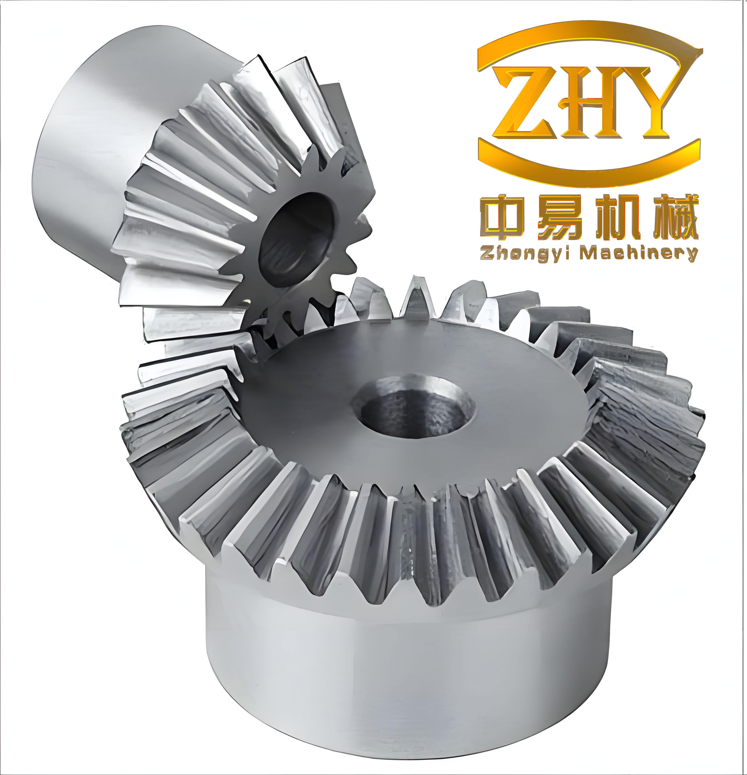
When I need to produce a straight bevel gear for intersecting shafts, I usually begin by checking whether a dedicated bevel gear planer or a modern gear cutting machine is available. In many repair shops, small workshops, and single-piece production environments, that equipment is not available. In those cases, I use a horizontal milling machine, a form-relieved disk-type module cutter, and a dividing head. This is an approximate method, but with careful setup, correct calculations, and controlled bias milling, it can produce a usable straight bevel gear for many service applications. The straight bevel gear is normally used for shafts whose axes intersect, most often at \(90^\circ\), although the shaft angle can also be less than \(90^\circ\). Because the method relies on a form cutter and an indexing device, I expect some indexing error and cutter installation error. As a result, my practical accuracy is generally in the range of grade 9 to grade 10. The process also requires several discontinuous indexing movements for each tooth, so productivity is lower than on a dedicated bevel gear machine. I therefore reserve this method for single-piece work, small-batch production, and repair or replacement of a straight bevel gear where the precision requirement is moderate.
In this article I describe the complete sequence I follow: selecting the cutter, inspecting and mounting the blank, setting the dividing head, cutting the central tooth slot, bias milling both sides of the large end, measuring the tooth thickness, and correcting the final shape. I also include the formulas and tables that I use most often. The most important idea is that a straight bevel gear has a tooth slot that is wide at the large end and narrow at the small end. A simple plunge cut with the form cutter cannot produce that taper correctly. Therefore, after cutting the central slot, I must bias mill each side of the slot. The quality of the finished straight bevel gear depends heavily on how well I control that bias milling operation.
Typical Data for a Straight Bevel Gear
I like to start with a clear set of drawing data. The following example represents a common straight bevel gear that I might machine on a horizontal milling machine. The module is \(m=3\,\text{mm}\), the number of teeth is \(z=25\), the pressure angle is \(20^\circ\), the pitch cone angle is \(45^\circ\), and the root cone angle is \(41^\circ 7’\). The pitch diameter is \(75\,\text{mm}\), the tip diameter is \(79.24\,\text{mm}\) with a tolerance range, the cone distance is \(53.03\,\text{mm}\), and the chordal tooth thickness at the pitch circle is \(4.71\,\text{mm}\) with a tolerance range. The chordal tooth height is \(3\,\text{mm}\), and the accuracy grade is 9HM according to the relevant standard. These values are enough for me to calculate the cutter number, the cutting depth, the offset, and the small-end dimensions.
| Parameter | Symbol | Value |
|---|---|---|
| Module | \(m\) | 3 mm |
| Number of teeth | \(z\) | 25 |
| Pressure angle | \(\alpha\) | 20° |
| Pitch cone angle | \(\delta\) | 45° |
| Root cone angle | \(\delta_f\) | 41°7′ |
| Pitch diameter | \(d\) | 75 mm |
| Tip diameter | \(d_a\) | 79.24 mm with tolerance |
| Cone distance | \(R\) | 53.03 mm |
| Chordal tooth thickness at pitch circle | \(s\) | 4.71 mm with tolerance |
| Chordal tooth height | \(h_a\) | 3 mm |
| Accuracy grade | — | 9HM |
For a straight bevel gear, the large end is the reference for most design parameters. This is important because the cutter profile is made to match the large end, while the cutter thickness is made to suit the small end. If I try to use a standard cylindrical gear cutter, the geometry will not match. The side of a proper bevel gear cutter is marked so that I do not confuse it with an ordinary gear cutter. The tooth profile of the cutter corresponds to the profile on a section perpendicular to the pitch cone surface. This is one reason why the straight bevel gear milling process is approximate: the cutter can only match one section accurately, while the real tooth changes continuously from the large end to the small end.
Why the Form Cutter Is Approximate
The large end and the small end of a straight bevel gear have different diameters. Therefore, their base circles are also different. The involute profile at the large end is flatter, while the profile at the small end is more curved. When I use a form cutter, the cutter has a fixed profile. If that profile is made correct for the large end, it cannot also be correct for the small end. Conversely, if I tried to make it correct for the small end, the large end would be wrong. Because the straight bevel gear is designed from the large-end parameters, the cutter profile is normally made according to the large end. However, the cutter thickness is made according to the small end. In a standard straight bevel gear, the small-end slot width is about two-thirds of the large-end slot width. Therefore, the cutter is made slightly thinner than the small-end slot width. This allows the cutter to enter the slot and also leaves material on both sides for bias milling.
This is the central limitation of milling a straight bevel gear on a horizontal milling machine. The finished tooth is not geometrically perfect. The small end may be slightly flatter than the true involute, and the tooth top may be thicker than ideal. In practice, I compensate by controlling the large-end and small-end tooth thickness carefully, and by filing the small end slightly after milling. If the finished straight bevel gear is intended for moderate service, this approximation is often acceptable. If the application requires high speed, high load, or precise motion, I prefer a dedicated bevel gear machine or a ground straight bevel gear.
Selecting the Correct Cutter for a Straight Bevel Gear
For a straight bevel gear, I do not select the cutter by the actual number of teeth alone. I select it by the equivalent number of teeth, also called the virtual number of teeth. The equivalent tooth number is calculated from the actual tooth number and the pitch cone angle. The formula I use is:
$$ z_v = \frac{z}{\cos \delta} $$
For the example straight bevel gear, \(z=25\) and \(\delta=45^\circ\). Therefore:
$$ z_v = \frac{25}{\cos 45^\circ} = \frac{25}{0.7071} = 35.35 $$
I round this value to 35. The cutter number is then chosen from the standard range for bevel gear cutters. A bevel gear cutter is normally made in eight numbers for each module, just like a standard involute gear cutter, but the tooth ranges are different. For a module of \(3\,\text{mm}\), I need a No. 6 bevel gear cutter because No. 6 covers 35 to 54 teeth. If I had selected a cutter for 25 teeth, I would have chosen the wrong profile. This is a common mistake when machining a straight bevel gear for the first time.
| Cutter number | Range of teeth that can be cut |
|---|---|
| 1 | 12 to 13 |
| 2 | 14 to 16 |
| 3 | 17 to 20 |
| 4 | 21 to 25 |
| 5 | 26 to 34 |
| 6 | 35 to 54 |
| 7 | 55 to 134 |
| 8 | 135 and above |
The cutter must also match the module and pressure angle of the straight bevel gear. I check the cutter marking, the module, and the pressure angle before mounting it on the arbor. The cutter should be sharp and free from chips or cracks. A dull cutter increases the cutting force and can push the workpiece away from the cutter, which makes the tooth thickness inconsistent. Because the straight bevel gear milling process already has limited accuracy, I try to remove as many avoidable errors as possible before the first cut.
Inspecting and Preparing the Blank
Before I mount the blank, I inspect the gear blank carefully. I check the cone angle and the back cone angle with a universal bevel protractor. I check the distance from the datum face to the outer circle. I also check the outside diameter and the bore size. If the blank is not correct, the finished straight bevel gear will not be correct, no matter how carefully I set the milling machine. I usually record the inspection results in a simple table so that I can compare them with the drawing before cutting.
| Inspection item | Method | Purpose |
|---|---|---|
| Cone angle and back cone angle | Universal bevel protractor | Confirm the blank geometry matches the straight bevel gear drawing |
| Distance from datum face to outer circle | Height gauge or depth micrometer | Ensure the axial location is correct |
| Outside diameter | Micrometer or caliper | Check the blank diameter before cutting |
| Bore size and runout | Micrometer and dial indicator | Ensure the blank fits the mandrel correctly |
| Face runout | Dial indicator | Reduce axial error during milling |
If the bore is the locating feature, I make sure it is clean and free from burrs. I also check that the blank can be seated firmly against the locating shoulder. For a straight bevel gear, any wobble in the blank will be magnified at the large end, so I do not skip this step.
Mounting the Straight Bevel Gear Blank
The method I use to mount the blank depends on its shape, size, and bore. I have three common methods. The first is a mandrel and nut arrangement. The mandrel shank has a Morse taper that fits the dividing head spindle bore, and I tighten it with a drawbar. The workpiece is fitted on the cylindrical portion of the mandrel. I indicate the workpiece, then tighten the nut to clamp it. This method is simple and works well for many medium-size straight bevel gears.
The second method is a micro-taper mandrel. I use this when the gear diameter is small, when the cone angle is large, or when the small-end slot bottom is very close to the bore surface. A micro-taper of about \(1:8000\) to \(1:1000\) can provide enough friction to hold the blank while leaving the outer face clear. This reduces the risk of the cutter striking the nut or the mandrel. The exact taper depends on the bore tolerance and the required clamping force.
The third method is direct clamping in a three-jaw self-centering chuck on the dividing head. I use this when the straight bevel gear has a large cone angle, a large diameter, a stepped end, or a bore large enough to allow safe clamping. In this case, I must check both radial and axial runout carefully. If the blank is not true, the tooth thickness will vary from tooth to tooth.
| Mounting method | Typical application | Alignment check |
|---|---|---|
| Mandrel and nut | General medium-size straight bevel gears | Indicate the blank after mounting; check face runout |
| Micro-taper mandrel | Small diameter, large cone angle, or clearance-limited parts | Usually self-aligning; check large-end face if needed |
| Three-jaw self-centering chuck | Large, stepped, or easily clamped blanks | Check radial runout at large and small ends, and face runout at large end |
If I use a dedicated fixture or a spring collet, I normally do not need to indicate the workpiece again. However, I still check that the fixture is clean and that the workpiece is fully seated. For a straight bevel gear, a small seating error can cause a large error at the tooth surface. When I use a clearance-fit mandrel or a chuck, I definitely indicate the large end and small end for radial runout and the large end face for axial runout. I prefer to keep the total indicated runout as small as possible before I start cutting.
Setting the Dividing Head
After mounting the workpiece, I set the dividing head on the milling machine table. I align the spindle axis with the feed direction. Then I tilt the dividing head spindle upward by the root cone angle \(\delta_f\). For the example straight bevel gear, \(\delta_f = 41^\circ 7’\). This tilt is called the cutting angle. It allows the cutter to follow the root cone of the straight bevel gear. If the angle is wrong, the tooth depth will be uneven from the large end to the small end, and the tooth profile will not match the drawing.
I verify the tilt angle with an angle gauge or a protractor. I also check that the dividing head is rigidly clamped to the table. During cutting, the interrupted cut of a straight bevel gear can cause vibration. If the dividing head is not clamped securely, the workpiece may move, and the tooth spacing may become irregular. I also check the dividing head for backlash. If the worm and worm wheel have excessive backlash, I always approach the indexing position from the same direction.
Setting the Cutting Depth and Cutting the Central Slot
Once the workpiece and dividing head are set, I align the cutter. I adjust the cutter so that its midplane passes through the axis of the workpiece. This is called centering the cutter. If the cutter is not centered, one side of the tooth slot will be deeper than the other, and the straight bevel gear will be asymmetric.
Next, I bring the cutter close to the large-end cone surface until it just touches. Then I retract the workpiece and raise the table by the full tooth depth at the large end. For a standard straight bevel gear, the full tooth depth at the large end is approximately:
$$ h = 2.2m $$
For the example, \(m=3\,\text{mm}\), so:
$$ h = 2.2 \times 3 = 6.6\,\text{mm} $$
If the module is large, I do not try to cut the full depth in one pass. I rough out the slot in two or three passes, leaving a small amount for the finishing pass. This reduces the load on the cutter and the dividing head. I also prefer to feed from the large end toward the small end. This direction helps prevent the dividing head spindle from lifting suddenly during the cut. If I feed from the small end toward the large end, the cutter tends to push the workpiece upward more strongly, which can cause a dangerous movement.
The first cut produces the central tooth slot. At this stage, the large-end tooth shape is partly formed, but the slot width is still not correct. The slot is too narrow on both sides, especially at the large end. A straight bevel gear requires a slot that is wide at the large end and narrow at the small end. The simple central cut does not produce enough taper in the slot width. Therefore, I must bias mill the two sides of the slot. This is the most important part of the process.
The Principle of Bias Milling a Straight Bevel Gear
The teeth and slots of a straight bevel gear are tapered. The large end is wide, and the small end is narrow. When I tilt the dividing head by the root cone angle, the large end of the workpiece is slightly higher than the small end. This makes the cutter cut deeper at the large end and slightly wider at the large end. However, the difference is not enough. I still need to remove additional material from both sides of the large end. In practice, each tooth slot usually requires three cuts: one central cut, one cut on one side, and one cut on the other side. The additional cuts are called bias milling.
The principle of bias milling is to combine two movements. First, I rotate the workpiece slightly about its own axis. Second, I move the table laterally so that the small-end slot is aligned with the cutter again. Because the large end and the small end have different radii, the same angular rotation produces different lateral displacements at the two ends. The difference between these displacements causes the cutter to remove more material at the large end than at the small end. This is exactly what a straight bevel gear needs. If I only rotate the workpiece without moving the table, the cutter will not align with the small end correctly. If I only move the table without rotating the workpiece, the cutter will not remove the correct side material. The combination of rotation and offset is the key.
There are several bias milling methods. No single method works perfectly for every straight bevel gear because the ratio of cone distance to face width, the cone angle, and the number of teeth all affect the result. I usually start with one of the standard methods and then correct the result by trial cutting. I always check the first two or three teeth before cutting the entire gear. This prevents wasting the whole blank if the setting is wrong.
Bias Milling Method One: Offset First, Rotation by Trial
In the first method, I calculate the lateral offset \(S\), and I determine the workpiece rotation by trial. The offset formula is:
$$ S = \frac{T}{2} – m x $$
In this formula, \(T\) is the cutter thickness at the mid-diameter, \(m\) is the module, and \(x\) is the offset coefficient. The offset coefficient depends on the cutter number and the ratio of cone distance to face width, \(R/b\). I obtain \(x\) from a standard table. For the example straight bevel gear, the cutter thickness measured with a gear tooth caliper is \(T = 2.58\,\text{mm}\). The cutter is No. 6, and the ratio \(R/b\) is about \(3:1\). From the table, \(x = 0.266\). Therefore:
$$ S = \frac{2.58}{2} – 3 \times 0.266 = 1.29 – 0.798 = 0.492\,\text{mm} $$
After calculating the offset, I rotate the dividing head and workpiece in the horizontal plane by a small trial angle. In one typical setup for this example, the trial rotation is about \(2^\circ 32’\). I then move the table laterally by \(S = 0.492\,\text{mm}\) so that the small-end slot is aligned with the cutter again. I record the rotation and offset. I cut one side of the tooth slot. Then I reverse the table movement by \(2S = 0.984\,\text{mm}\) and reverse the rotation by twice the trial angle. I cut the other side of the tooth slot. After cutting two or three teeth, I measure the large-end and small-end tooth thickness and adjust the settings if necessary.
For the small end of a straight bevel gear, the chordal tooth thickness and chordal tooth height are smaller than at the large end. I calculate them from the large-end values and the cone distance. The formulas I use are:
$$ s_x = s \frac{R-b}{R} $$
$$ h_x = h_a \frac{R-b}{R} $$
Here, \(s\) is the large-end chordal tooth thickness, \(h_a\) is the large-end chordal tooth height, \(R\) is the cone distance, and \(b\) is the face width. For the example, \(s = 4.71\,\text{mm}\), \(h_a = 3\,\text{mm}\), and \(R = 53.03\,\text{mm}\). If the face width is about \(18\,\text{mm}\), then:
$$ s_x = 4.71 \times \frac{53.03-18}{53.03} = 4.71 \times 0.6606 = 3.11\,\text{mm} $$
$$ h_x = 3 \times \frac{53.03-18}{53.03} = 3 \times 0.6606 = 1.98\,\text{mm} $$
These small-end values are useful when I check the finished straight bevel gear. If the measured small-end values do not match the calculated values, I correct the rotation and offset before cutting more teeth.
| Cutter number | 3:1 | 3.25:1 | 3.5:1 | 3.75:1 | 4:1 | 4.25:1 | 4.5:1 | 4.75:1 | 5:1 |
|---|---|---|---|---|---|---|---|---|---|
| 1 | 0.275 | 0.286 | 0.296 | 0.309 | 0.319 | 0.331 | 0.338 | 0.344 | 0.352 |
| 2 | 0.289 | 0.298 | 0.308 | 0.316 | 0.324 | 0.329 | 0.334 | 0.338 | 0.343 |
| 3 | 0.311 | 0.318 | 0.323 | 0.328 | 0.330 | 0.334 | 0.337 | 0.340 | 0.343 |
| 4 | 0.280 | 0.285 | 0.290 | 0.293 | 0.295 | 0.296 | 0.298 | 0.300 | 0.302 |
| 5 | 0.275 | 0.280 | 0.285 | 0.287 | 0.291 | 0.293 | 0.296 | 0.298 | 0.298 |
| 6 | 0.266 | 0.268 | 0.271 | 0.273 | 0.275 | 0.278 | 0.280 | 0.282 | 0.283 |
| 7 | 0.266 | 0.268 | 0.271 | 0.272 | 0.273 | 0.274 | 0.274 | 0.275 | 0.277 |
| 8 | 0.254 | 0.254 | 0.255 | 0.256 | 0.257 | 0.257 | 0.257 | 0.258 | 0.258 |
Bias Milling Method Two: Rotation First, Offset by Trial
In the second method, I calculate the rotation of the dividing head handle first, and I determine the table offset by trial. The rotation is expressed as a number of holes on a selected index circle. The approximate formula is:
$$ N = \frac{k}{z} H $$
In this formula, \(N\) is the number of holes I move the index handle, \(z\) is the number of teeth in the straight bevel gear, \(H\) is the number of holes in the selected index circle, and \(k\) is a coefficient. When the tooth count is small, I take \(k=4\). When the tooth count is large, I take \(k=5\). For the example, \(z=25\), so I use \(k=4\). If I choose the 25-hole circle, then:
$$ N = \frac{4}{25} \times 25 = 4\,\text{holes} $$
This means that during bias milling, I first turn the index handle by four hole spaces on the 25-hole circle. This rotates the straight bevel gear by a small amount. I then move the table laterally until the small-end slot is aligned with the cutter again. I record the offset \(S\). I cut one side of the slot, then reverse the offset and the handle rotation for the other side. This method is convenient because the rotation is easy to repeat with the index plate. However, the offset still depends on the cutter thickness and the gear geometry, so I always confirm it by trial cut.
The rotation must be enough to remove material from the large end without overcutting the small end. If the rotation is too large, the small end may become too thin. If the rotation is too small, the large end will remain too thick. The offset controls how much of the rotation is compensated at the small end. By adjusting both, I can bring the straight bevel gear closer to the required tooth thickness at both ends.
Bias Milling Method Three: Horizontal Swivel and Offset
The third method combines a horizontal swivel of the dividing head with a lateral table offset. I first calculate the horizontal swivel angle \(\alpha\), and I determine the table offset by trial. An approximate relation I use is:
$$ \alpha \approx \frac{180}{\pi}\frac{S}{R} $$
In this expression, \(\alpha\) is in degrees, \(S\) is the lateral offset, and \(R\) is the cone distance. For the example, if \(S=0.492\,\text{mm}\) and \(R=53.03\,\text{mm}\), then:
$$ \alpha \approx \frac{180}{\pi}\frac{0.492}{53.03} = 0.53^\circ $$
This value is only a starting point. Because the straight bevel gear has a tapered tooth and the cutter has finite thickness, the actual swivel angle must be corrected by trial. I set the swivel angle, move the table laterally by the trial offset, and cut one side of the tooth slot. Then I measure the tooth thickness at the large end and the small end. If the large end is still thick, I increase the swivel angle or the offset. If the small end is too thin, I reduce the swivel angle or increase the offset in the appropriate direction. This method is useful when the dividing head is mounted on a swivel base and the setup is rigid enough to hold the angle.
| Method | First setting | Second setting | Best use |
|---|---|---|---|
| Method one | Calculate offset \(S\) | Find rotation by trial | General straight bevel gear work with known cutter thickness |
| Method two | Calculate handle rotation \(N\) | Find offset by trial | Shops that prefer index-hole settings |
| Method three | Calculate swivel angle \(\alpha\) | Find offset by trial | Dividing head with a swivel base and good rigidity |
Measuring the Straight Bevel Gear Tooth Thickness
After bias milling two or three teeth, I stop and measure the straight bevel gear. I use a gear tooth caliper to measure the chordal tooth thickness and chordal tooth height at the large end. I also measure the small end. The large end is the main reference, but the small end must also be controlled to avoid interference. If the small end is too thick, the teeth may interfere during meshing. If the small end is too thin, the contact area will be too small, and the tooth may be weak.
The measurement should be taken at the correct chordal height. If the chordal height is not set correctly on the caliper, the chordal tooth thickness reading will be inaccurate. I always zero the caliper and check it against a known setting before measuring the straight bevel gear. I also make sure the tooth surface is clean and free from burrs. A small burr can change the reading by several hundredths of a millimeter.
When I compare the measured values with the calculated values, I use the following correction rules. These rules are based on the relationship between rotation, offset, and the material removed at the large and small ends.
| Condition after trial cut | Correction | Effect |
|---|---|---|
| Small end is correct, but large end still has material | Increase rotation \(N\) or swivel angle \(\alpha\), and increase offset \(S\) | Increases the difference so the small end is not cut further while the large end is cut more |
| Large end is correct, but small end is still thick | Reduce rotation \(N\) or swivel angle \(\alpha\), and reduce offset \(S\) more | Allows the small end to be cut a little while the large end is not cut further |
| Both large and small ends have equal material | Reduce offset \(S\) only | Cuts both ends a little without changing the taper relationship too much |
| Small end is correct, but large end is too small | Reduce rotation \(N\) or swivel angle \(\alpha\), and reduce offset \(S\) moderately | Stops cutting the small end and removes less from the large end than before |
| Large end is correct, but small end is too small | Increase rotation \(N\) or swivel angle \(\alpha\), and increase offset \(S\) more | Stops cutting the small end more than necessary |
| Small end is already too small after the central cut | Change the cutter or make a special cutter | The cutter is too thick for the required small-end slot width |
These corrections are not independent. If I change the rotation, I must usually change the offset as well. I make small adjustments and cut one or two teeth at a time. For a straight bevel gear, patience during the trial stage saves time and material later. Once I have the correct settings, I can cut all the remaining teeth with confidence.
Finishing the Straight Bevel Gear
After all teeth are milled, I inspect the straight bevel gear again. Even with careful bias milling, the small-end tooth profile is usually flatter than the theoretical involute. The tooth top at the small end may also be thicker than desired. If the gear is used with a mating straight bevel gear and the backlash is small, the flatter small-end profile can cause interference. To reduce this risk, I use a fine file to relieve the small end slightly. I file more near the small end and less toward the large end. The goal is to make the small-end curve slightly more curved and bring it closer to the correct tooth form.
If the application does not require a high degree of precision, I may intentionally make the small end slightly thinner. This helps prevent interference without requiring extensive hand filing. However, I do not make the small end too thin because that reduces the load-carrying capacity of the straight bevel gear. I also remove all burrs from the tooth edges and the slot bottoms. A deburred straight bevel gear is safer to handle and meshes more smoothly.
I check the final tooth thickness at several positions around the gear. If the readings vary, the dividing head or the workpiece may have moved during cutting. I also check the radial runout and the face runout again. For a straight bevel gear, the final inspection should include the large-end chordal tooth thickness, the small-end chordal tooth thickness, the chordal tooth height, the tooth spacing, and the runout. If a gear tooth caliper is available, it is the most convenient tool for checking the tooth thickness. If not, I use a suitable chordal measurement over pins or a span measurement, depending on the gear size and geometry.
Example Calculation Summary
For the example straight bevel gear, I summarize the main calculations below. This table is useful when I want to see all the settings together before I start cutting.
| Item | Formula | Result |
|---|---|---|
| Equivalent teeth | \( z_v = z / \cos \delta \) | 35.35, choose No. 6 cutter |
| Full tooth depth at large end | \( h = 2.2m \) | 6.6 mm |
| Offset coefficient | From table for No. 6 and \(R/b \approx 3:1\) | \(x = 0.266\) |
| Cutter thickness at mid-diameter | Measured | \(T = 2.58\,\text{mm}\) |
| Lateral offset | \( S = T/2 – m x \) | 0.492 mm |
| Small-end chordal tooth thickness | \( s_x = s(R-b)/R \) | 3.11 mm when \(b \approx 18\,\text{mm}\) |
| Small-end chordal tooth height | \( h_x = h_a(R-b)/R \) | 1.98 mm when \(b \approx 18\,\text{mm}\) |
| Index handle rotation, method two | \( N = (k/z)H \) | 4 holes on a 25-hole circle |
| Approximate swivel angle, method three | \( \alpha \approx (180/\pi)(S/R) \) | About 0.53° as a starting value |
Practical Notes for Milling a Straight Bevel Gear
I have learned that the setup is more important than the cutting speed. A rigid setup produces a more consistent straight bevel gear. I make sure the arbor is tight, the cutter is sharp, and the workpiece is clamped securely. I also check the dividing head for backlash and the table for looseness. Any play in the machine will appear as tooth thickness variation. Because the straight bevel gear is cut with a form cutter, the cutting force is interrupted. This can cause chatter, especially on large modules. If chatter occurs, I reduce the feed rate, reduce the depth of cut, and increase the rigidity of the setup.
I also pay attention to chip evacuation. A straight bevel gear cut produces chips that can pack into the tooth slot. If the chips are not cleared, the cutter may rub instead of cut, and the tooth surface will become rough. I use a brush or an air blast to clear the chips when necessary. Coolant can help, but I make sure it does not wash chips into the dividing head or the table ways. For cast iron, I often cut dry and use an air blast. For steel, I use a suitable cutting fluid to reduce heat and improve surface finish.
When I cut a straight bevel gear with a small number of teeth, the approximation error is larger. The small-end curve becomes flatter, and the risk of interference increases. In such cases, I pay extra attention to the small-end tooth thickness and the hand filing operation. If the gear is part of a pair, I check the meshing pattern with the mating straight bevel gear. A small amount of lapping compound can help show the contact area, but I do not use excessive lapping because it can change the tooth thickness.
For a large straight bevel gear, the workpiece may be heavy and the dividing head may be overloaded. I use a support if necessary and make sure the table is not raised too high. I also avoid taking heavy cuts near the end of the tooth because the interrupted cut can cause the workpiece to spring. If the machine is not rigid enough, I take more passes with smaller depth. The total cutting time is longer, but the straight bevel gear quality is better.
Quality, Limitations, and Best Applications
The milling method I have described is an approximate method. It is not a replacement for a dedicated bevel gear generator. The finished straight bevel gear will usually be in the grade 9 to grade 10 range. The tooth profile at the small end will not be exactly involute. The tooth spacing may vary slightly because of indexing errors. The tooth thickness may vary because of cutter wear, workpiece movement, and table offset errors. Despite these limitations, the method is valuable for repair work, replacement parts, and low-speed power transmission where a perfect straight bevel gear is not required.
I use this method when the following conditions are present: the equipment is a horizontal milling machine with a dividing head; the batch size is one or a few pieces; the module is within the capacity of the available cutter; the accuracy requirement is moderate; and the straight bevel gear can be adjusted during assembly. If the application requires high speed, low noise, long life, or precise motion, I recommend a generated straight bevel gear or a ground straight bevel gear. The extra cost is justified by the improved geometry and load capacity.
One of the most important practical points is that the straight bevel gear should be checked as a pair whenever possible. The large-end tooth thickness, small-end tooth thickness, and backlash all affect how the pair meshes. If I only check one gear, I may not detect an interference problem at the small end. By checking the pair, I can adjust the final filing and lapping to obtain a smooth contact pattern. The contact pattern should be centered on the tooth and should not concentrate at the small end or the tooth tip.
Final Procedure I Follow
For clarity, I summarize the complete procedure I follow when milling a straight bevel gear on a horizontal milling machine. First, I read the drawing and record the module, number of teeth, pressure angle, pitch cone angle, root cone angle, cone distance, face width, pitch diameter, tip diameter, chordal tooth thickness, chordal tooth height, and accuracy grade. Second, I calculate the equivalent teeth and select the correct bevel gear cutter. Third, I inspect the blank for cone angle, back cone angle, outside diameter, bore, and runout. Fourth, I mount the blank on a suitable mandrel or chuck and indicate it as required. Fifth, I set the dividing head, align its spindle with the feed direction, and tilt it to the root cone angle. Sixth, I center the cutter and set the depth to \(2.2m\). Seventh, I cut the central slot, feeding from the large end to the small end. Eighth, I bias mill one side of the slot using a calculated offset and a trial rotation. Ninth, I bias mill the other side by reversing the offset and rotation. Tenth, I measure the large-end and small-end tooth thickness and correct the settings. Eleventh, I cut all remaining teeth. Twelfth, I deburr, file the small end if needed, and inspect the finished straight bevel gear.
This procedure is not fast, but it is reliable. The straight bevel gear is a challenging part to machine without specialized equipment. By understanding the geometry, using the correct cutter, controlling the bias milling carefully, and checking the result at every stage, I can produce a serviceable straight bevel gear in a general machine shop. The method requires patience and attention to detail, but it has saved many repair jobs where a replacement straight bevel gear was not available or would take too long to order.
In my experience, the most common cause of failure is not the machine or the cutter. It is a lack of control during bias milling. If I rush the trial cuts, I usually end up with a straight bevel gear that is too thin at the small end or too thick at the large end. If I take the time to measure and correct after the first two or three teeth, the rest of the gear usually comes out well. The straight bevel gear may not be perfect, but it can perform its function reliably when the application is appropriate. For anyone who works with intersecting shafts and does not have a dedicated bevel gear machine, this milling method is a practical skill worth mastering.