
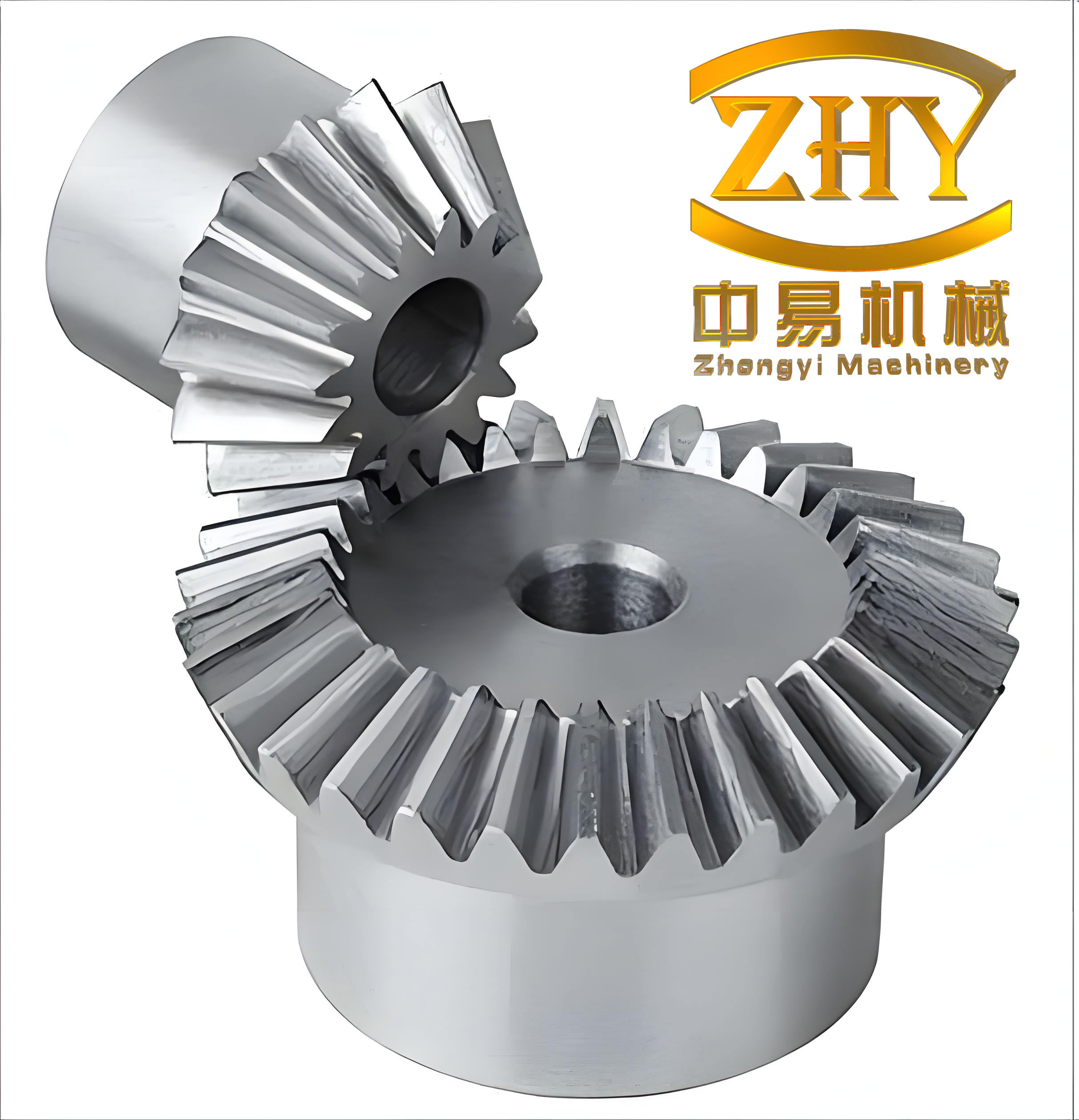
Introduction. In my work on the design and manufacture of straight bevel gear pairs, I have repeatedly found that the big-end tooth thickness is one of the most sensitive parameters in the entire geometric chain. A straight bevel gear transmits motion and torque between intersecting axes, and its teeth are not prismatic. They are tapered, curved in three dimensions, and generated by a spherical involute process. The big end of a straight bevel gear is normally the reference location for standardized parameters such as module, pressure angle, addendum, and tooth thickness. If the big-end tooth thickness is calculated only by an approximate equivalent spur gear, the resulting value can deviate from the true spherical geometry. That deviation may appear small in numerical terms, but in a straight bevel gear it can influence contact pattern, backlash, tooth strength, cutting depth, inspection, and final meshing quality.
I therefore present a precise calculation method for the big-end tooth thickness of a straight bevel gear. The method starts from the true generation principle of the straight bevel gear tooth surface and the big-end tooth profile. I derive the spherical involute expression in a fixed coordinate system, then use that expression to calculate both the chord tooth thickness and the arc tooth thickness. The procedure avoids the geometric approximation embedded in the conventional equivalent gear method. It is suitable for manual calculation, spreadsheet implementation, or integration into a dedicated straight bevel gear design tool.
Why the equivalent gear method is approximate. The traditional approach replaces the straight bevel gear at its big end by a virtual spur gear, often called the equivalent gear or virtual gear. The equivalent number of teeth is obtained from the pitch cone angle and the actual number of teeth. The tooth profile of that virtual spur gear is an involute in a plane, while the true tooth profile of a straight bevel gear is a spherical involute on a sphere centered at the cone apex. A plane involute and a spherical involute coincide only in a limiting sense; they are not identical for finite cone angles. The difference becomes more noticeable at larger cone angles, at greater addendum heights, and whenever the tooth thickness is measured away from the pitch point. For a straight bevel gear, the big-end profile is a spherical curve, so a precise calculation must be based on spherical geometry.
Generation of the straight bevel gear tooth surface. I consider a base cone and a generating plane. The generating plane is tangent to the base cone and has its center at the same apex as the base cone. The radius of the generating plane is equal to the cone distance of the straight bevel gear. When the generating plane rolls without slipping on the base cone, a straight line in that plane, passing through the apex, sweeps the tooth surface of the straight bevel gear. The intersection of that generated surface with a sphere centered at the apex is the spherical involute. This spherical involute is the true big-end tooth profile of the straight bevel gear.
Coordinate systems. I introduce a fixed coordinate system \(S(x,y,z)\) and an auxiliary moving coordinate system \(S_1(x_1,y_1,z_1)\). In the fixed system, the origin is the cone apex. The \(z\) axis coincides with the axis of the base cone and points from the apex toward the base. The \(x\) axis lies along the base-cone radius that corresponds to the starting point of the spherical involute. The \(y\) axis follows the right-hand rule. In the moving system, the origin is also the cone apex. The \(z_1\) axis is the instantaneous rolling axis between the generating plane and the base cone. The \(x_1\) axis lies in the generating plane and is perpendicular to \(z_1\). The \(y_1\) axis is again determined by the right-hand rule.
| Symbol | Meaning |
|---|---|
| \(R\) | Cone distance of the straight bevel gear |
| \(\delta_b\) | Base cone angle |
| \(\delta\) | Pitch cone angle |
| \(\delta_a\) | Addendum cone angle |
| \(\delta_n\) | Arbitrary cone angle at which tooth thickness is evaluated |
| \(\phi\) | Rolling parameter of the generating plane |
| \(\psi\) | Angle between the cone distance line and the instantaneous rolling axis |
| \(m\) | Big-end module of the straight bevel gear |
| \(z\) | Number of teeth of the straight bevel gear |
| \(\alpha\) | Pressure angle |
| \(S_n\) | Chord tooth thickness at a specified cone angle |
| \(\overset{\frown}{S}_n\) | Arc tooth thickness at a specified cone angle |
Point on the generating plane. Let \(K\) be a point on the spherical involute at a particular instant. In the moving coordinate system \(S_1\), the coordinates of \(K\) can be written in terms of the angle \(\psi\), which is measured between the cone distance line \(OK\) and the instantaneous rolling axis \(ON\). Because the point lies on a sphere of radius \(R\), I write
$$
x_1 = R\sin\psi,\qquad y_1 = 0,\qquad z_1 = R\cos\psi .
$$
The pure rolling condition states that the arc length rolled on the base cone equals the corresponding arc length on the base circle of the generating plane. If \(\phi\) is the angular position of the generating plane relative to its starting position, then the arc length on the base cone is
$$
\overset{\frown}{NA} = \phi R \sin\delta_b .
$$
The arc length on the generating plane is
$$
\overset{\frown}{NK} = \psi R .
$$
Equating the two arc lengths gives
$$
\psi = \phi \sin\delta_b .
$$
Substituting this relation into the expression for \(K\) in \(S_1\), I obtain the moving-coordinate representation of the spherical involute point:
$$
x_1 = R\sin(\phi\sin\delta_b),\qquad y_1 = 0,\qquad z_1 = R\cos(\phi\sin\delta_b).
$$
Transformation to the fixed system. The moving coordinate system is obtained from the fixed system by two rotations. First, a rotation aligns the base cone axis with the instantaneous rolling axis. Second, a rotation accounts for the angular position \(\phi\) of the generating plane. Using homogeneous transformation matrices, the coordinate transformation can be written as
$$
\begin{bmatrix}
x\\
y\\
z\\
1
\end{bmatrix}
=
M_1 M_2
\begin{bmatrix}
x_1\\
y_1\\
z_1\\
1
\end{bmatrix},
$$
where
$$
M_1 =
\begin{bmatrix}
\sin\phi & \cos\phi & 0 & 0\\
-\cos\phi & \sin\phi & 0 & 0\\
0 & 0 & 1 & 0\\
0 & 0 & 0 & 1
\end{bmatrix},
$$
and
$$
M_2 =
\begin{bmatrix}
1 & 0 & 0 & 0\\
0 & \cos\delta_b & \sin\delta_b & 0\\
0 & -\sin\delta_b & \cos\delta_b & 0\\
0 & 0 & 0 & 1
\end{bmatrix}.
$$
After multiplying the matrices and simplifying the trigonometric terms, I obtain the big-end spherical involute of the straight bevel gear in the fixed coordinate system \(S\):
$$
\begin{aligned}
Q_x(\phi) &= R\left[\cos(\phi\sin\delta_b)\sin\delta_b\cos\phi + \sin(\phi\sin\delta_b)\sin\phi\right],\\
Q_y(\phi) &= R\left[\cos(\phi\sin\delta_b)\sin\delta_b\sin\phi – \sin(\phi\sin\delta_b)\cos\phi\right],\\
Q_z(\phi) &= R\cos(\phi\sin\delta_b)\cos\delta_b.
\end{aligned}
$$
This is the central geometric result of my calculation. It describes every point on the big-end spherical involute of the straight bevel gear as a function of the rolling parameter \(\phi\). The parameter range begins at the base cone and extends to the addendum cone. For a point on the addendum cone, the maximum value of \(\phi\) is
$$
\phi_{\max} =
\frac{\arccos\left(\frac{\cos\delta_a}{\cos\delta_b}\right)}{\sin\delta_b}.
$$
Thus, for any cone angle \(\delta_n\) between the base cone and the addendum cone, the corresponding value of \(\phi\) is
$$
\phi_n =
\frac{\arccos\left(\frac{\cos\delta_n}{\cos\delta_b}\right)}{\sin\delta_b}.
$$
Relating the spherical involute to cone angle. For a point on the spherical involute, the \(z\) coordinate in the fixed system is related to the cone angle by
$$
Q_z(\phi_n) = R\cos\delta_n.
$$
Using the expression for \(Q_z\), this becomes
$$
R\cos(\phi_n\sin\delta_b)\cos\delta_b = R\cos\delta_n.
$$
Therefore,
$$
\cos(\phi_n\sin\delta_b) = \frac{\cos\delta_n}{\cos\delta_b},
$$
which gives the inverse relation already stated:
$$
\phi_n =
\frac{\arccos\left(\frac{\cos\delta_n}{\cos\delta_b}\right)}{\sin\delta_b}.
$$
This relation is important because it allows me to evaluate the tooth thickness of a straight bevel gear at any chosen cone angle, not only at the addendum or at the pitch cone. The same expression can be used for the pitch cone by setting \(\delta_n=\delta\).
Angular position of a spherical involute point. To calculate tooth thickness, I need the angular position of a point on the spherical involute in the base plane. I define the vector from the apex to the base-cone starting point as
$$
\mathbf{r}_1 = (R\sin\delta_b,\,0,\,0).
$$
For an arbitrary point on the spherical involute at cone angle \(\delta_n\), I define the projected radius vector in the \(xy\) plane as
$$
\mathbf{r}_2 = (Q_x(\phi_n),\,Q_y(\phi_n),\,0).
$$
The angle between \(\mathbf{r}_1\) and \(\mathbf{r}_2\) is
$$
\theta_n =
\arccos\left(
\frac{\mathbf{r}_1\cdot\mathbf{r}_2}{|\mathbf{r}_1||\mathbf{r}_2|}
\right).
$$
Because \(|\mathbf{r}_1|=R\sin\delta_b\) and \(|\mathbf{r}_2|=R\sin\delta_n\), this simplifies to
$$
\theta_n =
\arccos\left[
\frac{Q_x(\phi_n)}{R\sin\delta_n}
\right],
\qquad
\phi_n =
\frac{\arccos\left(\frac{\cos\delta_n}{\cos\delta_b}\right)}{\sin\delta_b}.
$$
For the pitch cone, I set \(\delta_n=\delta\), so
$$
\theta_1 =
\arccos\left[
\frac{Q_x(\phi_p)}{R\sin\delta}
\right],
\qquad
\phi_p =
\frac{\arccos\left(\frac{\cos\delta}{\cos\delta_b}\right)}{\sin\delta_b}.
$$
Here \(\theta_1\) is the angular distance from the base-cone starting radius to the pitch point on the spherical involute of the straight bevel gear.
Half tooth angular thickness at the pitch cone. The arc tooth thickness on the pitch cone of a standard straight bevel gear is half the circular pitch. Therefore,
$$
\overset{\frown}{s}_p = \frac{\pi m}{2}.
$$
The corresponding pitch radius in the base plane is
$$
r_p = R\sin\delta.
$$
The angular half thickness at the pitch cone is therefore
$$
\theta_2 = \frac{\overset{\frown}{s}_p/2}{r_p}
= \frac{\pi m}{4R\sin\delta}.
$$
This angle locates the centerline of the tooth relative to the pitch point on the spherical involute. Combining \(\theta_1\) and \(\theta_2\), I obtain the angular position of the tooth centerline relative to the base-cone starting radius:
$$
\theta = \theta_1 + \theta_2.
$$
Chord tooth thickness of the straight bevel gear. To compute the chord tooth thickness, I rotate the fixed coordinate system by the angle \(\theta\) so that the new \(x_2\) axis coincides with the tooth centerline. The transformation is
$$
\begin{aligned}
x_2 &= Q_x(\phi)\cos\theta + Q_y(\phi)\sin\theta,\\
y_2 &= -Q_x(\phi)\sin\theta + Q_y(\phi)\cos\theta,\\
z_2 &= Q_z(\phi).
\end{aligned}
$$
In this rotated system, the \(y_2\) coordinate measures the perpendicular distance from the tooth centerline to one side of the spherical involute. Because the tooth is symmetric about the centerline, the big-end chord tooth thickness at a specified cone angle is twice the absolute value of \(y_2\):
$$
S_n = 2|y_2|
= 2\left|Q_y(\phi_n)\cos\theta – Q_x(\phi_n)\sin\theta\right|.
$$
For the addendum cone, I replace \(\phi_n\) by \(\phi_a\), where
$$
\phi_a =
\frac{\arccos\left(\frac{\cos\delta_a}{\cos\delta_b}\right)}{\sin\delta_b}.
$$
Thus, the addendum chord tooth thickness of the straight bevel gear is
$$
S_a = 2\left|Q_y(\phi_a)\cos\theta – Q_x(\phi_a)\sin\theta\right|.
$$
Arc tooth thickness of the straight bevel gear. The arc tooth thickness is the spherical distance along the big-end sphere between the two corresponding points on the two sides of the tooth. In my formulation, one side of the tooth is represented by the spherical involute at angle \(\theta_n\), and the tooth centerline is at angle \(\theta\). The angular half thickness at the chosen cone angle is therefore \(\theta-\theta_n\). Multiplying by the local radius \(R\sin\delta_n\) gives the arc half thickness, so the full arc tooth thickness is
$$
\overset{\frown}{S}_n = 2(\theta-\theta_n)R\sin\delta_n.
$$
Substituting the expression for \(\theta_n\), I obtain the completely explicit form
$$
\overset{\frown}{S}_n =
2\left[
\theta –
\arccos\left(
\frac{Q_x(\phi_n)}{R\sin\delta_n}
\right)
\right]
R\sin\delta_n,
$$
with
$$
\phi_n =
\frac{\arccos\left(\frac{\cos\delta_n}{\cos\delta_b}\right)}{\sin\delta_b}.
$$
At the addendum cone, this becomes
$$
\overset{\frown}{S}_a = 2(\theta-\theta_a)R\sin\delta_a,
$$
where
$$
\theta_a =
\arccos\left[
\frac{Q_x(\phi_a)}{R\sin\delta_a}
\right].
$$
Complete calculation procedure. I summarize the precise calculation method for the big-end tooth thickness of a straight bevel gear in the following steps. The method is deterministic and can be repeated for any cone angle.
| Step | Operation | Result |
|---|---|---|
| 1 | Input the straight bevel gear parameters \(m\), \(R\), \(z\), \(\delta\), \(\delta_a\), \(\delta_b\), and \(\alpha\). | Design data set |
| 2 | Compute the pitch-point rolling parameter from \(\phi_p=\arccos(\cos\delta/\cos\delta_b)/\sin\delta_b\). | \(\phi_p\) |
| 3 | Evaluate \(Q_x(\phi_p)\) and \(Q_y(\phi_p)\) using the spherical involute equations. | Pitch-point coordinates |
| 4 | Compute \(\theta_1=\arccos[Q_x(\phi_p)/(R\sin\delta)]\). | Base-to-pitch angle |
| 5 | Compute \(\theta_2=\pi m/(4R\sin\delta)\). | Half angular thickness at pitch cone |
| 6 | Compute the tooth centerline angle \(\theta=\theta_1+\theta_2\). | \(\theta\) |
| 7 | For the desired cone angle \(\delta_n\), compute \(\phi_n=\arccos(\cos\delta_n/\cos\delta_b)/\sin\delta_b\). | \(\phi_n\) |
| 8 | Evaluate \(Q_x(\phi_n)\), \(Q_y(\phi_n)\), and \(Q_z(\phi_n)\). | Involute coordinates |
| 9 | Compute chord thickness \(S_n=2|Q_y(\phi_n)\cos\theta-Q_x(\phi_n)\sin\theta|\). | Chord tooth thickness |
| 10 | Compute \(\theta_n=\arccos[Q_x(\phi_n)/(R\sin\delta_n)]\). | Involute angular position |
| 11 | Compute arc thickness \(\overset{\frown}{S}_n=2(\theta-\theta_n)R\sin\delta_n\). | Arc tooth thickness |
Numerical example for a straight bevel gear. I apply the method to a straight bevel gear with the following parameters. The values are chosen to represent a typical small-module straight bevel gear with a pressure angle of \(20^\circ\).
| Parameter | Value |
|---|---|
| Module \(m\) | 3 mm |
| Cone distance \(R\) | 53 mm |
| Number of teeth \(z\) | 25 |
| Addendum cone angle \(\delta_a\) | \(48^\circ 15’\) |
| Pitch cone angle \(\delta\) | \(45^\circ\) |
| Base cone angle \(\delta_b\) | \(41^\circ 38’\) |
| Pressure angle \(\alpha\) | \(20^\circ\) |
Using the pitch cone data, I compute the rolling parameter at the pitch point:
$$
\phi_p =
\frac{\arccos\left(\frac{\cos45^\circ}{\cos41^\circ 38′}\right)}
{\sin41^\circ 38′}
= 0.497.
$$
For the addendum cone, the rolling parameter is
$$
\phi_a =
\frac{\arccos\left(\frac{\cos48^\circ 15′}{\cos41^\circ 38′}\right)}
{\sin41^\circ 38′}
= 0.710.
$$
Evaluating the spherical involute coordinates at the pitch point and then calculating the angular position gives
$$
\theta_1 = 0.020.
$$
The half angular thickness at the pitch cone is
$$
\theta_2 =
\frac{\pi \times 3}{4 \times 53 \times \sin45^\circ}
= 0.063.
$$
Therefore, the tooth centerline angle is
$$
\theta = \theta_1+\theta_2 = 0.020+0.063 = 0.083.
$$
At the addendum cone, the angular position of the spherical involute point is
$$
\theta_a = 0.055.
$$
The addendum chord tooth thickness of the straight bevel gear is
$$
S_a =
2\left|Q_y(\phi_a)\cos0.083 – Q_x(\phi_a)\sin0.083\right|
= 2.205\text{ mm}.
$$
The addendum arc tooth thickness of the straight bevel gear is
$$
\overset{\frown}{S}_a =
2(0.083-0.055)\times53\times\sin48^\circ 15′
= 2.214\text{ mm}.
$$
These results are summarized in the following table.
| Quantity | Symbol | Value |
|---|---|---|
| Pitch-point rolling parameter | \(\phi_p\) | 0.497 |
| Addendum rolling parameter | \(\phi_a\) | 0.710 |
| Base-to-pitch angular position | \(\theta_1\) | 0.020 rad |
| Half angular thickness at pitch cone | \(\theta_2\) | 0.063 rad |
| Tooth centerline angle | \(\theta\) | 0.083 rad |
| Addendum involute angular position | \(\theta_a\) | 0.055 rad |
| Addendum chord tooth thickness | \(S_a\) | 2.205 mm |
| Addendum arc tooth thickness | \(\overset{\frown}{S}_a\) | 2.214 mm |
Comparison with the equivalent gear method. The traditional equivalent gear calculation treats the straight bevel gear as a virtual spur gear at the big end. The virtual number of teeth is
$$
z_v = \frac{z}{\cos\delta} = \frac{25}{\cos45^\circ} = 35.355.
$$
The virtual pitch radius is
$$
r = \frac{m z_v}{2} = \frac{3\times35.355}{2}=53.033\text{ mm}.
$$
The virtual addendum radius is
$$
r_a = r + h_a^*m = 53.033+3=56.033\text{ mm}.
$$
The virtual base radius is
$$
r_b = r\cos\alpha = 53.033\cos20^\circ = 49.834\text{ mm}.
$$
The addendum pressure angle is
$$
\alpha_a = \arccos\left(\frac{r_b}{r_a}\right) = 0.475\text{ rad}.
$$
The involute functions are
$$
\operatorname{inv}\alpha = \tan\alpha-\alpha = 0.015,
\qquad
\operatorname{inv}\alpha_a = \tan\alpha_a-\alpha_a = 0.039.
$$
The tooth thickness on the virtual pitch circle is
$$
s = \frac{\pi m}{2}=4.712\text{ mm}.
$$
The addendum tooth thickness obtained by the equivalent gear method is
$$
\overset{\frown}{s}_a =
\frac{r_a}{r}s –
2r_a(\operatorname{inv}\alpha_a-\operatorname{inv}\alpha)
=2.256\text{ mm}.
$$
Comparing this value with the precise arc tooth thickness from the spherical involute method gives
$$
\Delta = \overset{\frown}{s}_a – \overset{\frown}{S}_a
=2.256-2.214=0.042\text{ mm}.
$$
The relative difference is
$$
\frac{\Delta}{\overset{\frown}{S}_a}
=
\frac{0.042}{2.214}
\approx 0.019,
$$
or approximately \(1.9\%\). For a straight bevel gear with a module of 3 mm, this is a meaningful deviation. The equivalent gear method overestimates the big-end addendum tooth thickness in this example. Such an overestimate can lead to an incorrect tooth thickness setting, excessive backlash after cutting, or a contact pattern that is shifted along the tooth height.
| Method | Basis | Addendum arc thickness | Difference |
|---|---|---|---|
| Precise spherical involute method | True spherical involute of straight bevel gear | 2.214 mm | Reference |
| Equivalent gear method | Virtual plane involute spur gear | 2.256 mm | +0.042 mm |
Interpretation of the result. The difference between the two methods arises because the equivalent gear method replaces the spherical tooth profile by a planar involute profile. This replacement is convenient and often acceptable for preliminary design, but it is not exact. The error is not a numerical rounding error; it is a geometric modeling error. In my calculation, the spherical involute is evaluated directly on the sphere of radius \(R\), and the chord and arc thicknesses are obtained from the true three-dimensional coordinates of the straight bevel gear tooth surface. Therefore, the result is consistent with the actual generation principle of the straight bevel gear.
Chord thickness versus arc thickness. The chord tooth thickness and arc tooth thickness are different measures of the same straight bevel gear tooth. The arc thickness follows the spherical surface, while the chord thickness is a straight-line distance between the two corresponding points on the tooth flanks. For inspection with a gear tooth caliper, the chord thickness is often more directly useful. For cutting and theoretical analysis, the arc thickness is often more convenient because it is proportional to angular tooth thickness. My method provides both quantities from the same set of coordinates, so the user does not need to switch between incompatible approximations.
| Measure | Geometric meaning | Typical use |
|---|---|---|
| Arc tooth thickness | Spherical arc length along the big-end cone at a specified cone angle | Theoretical design, contact analysis, backlash calculation |
| Chord tooth thickness | Straight-line distance between corresponding points on the two tooth flanks | Inspection, caliper measurement, manufacturing setting |
Extension to any position on the straight bevel gear tooth. One advantage of the spherical involute formulation is that the cone distance \(R\) and the cone angle \(\delta_n\) appear explicitly. If I change \(R\), I can evaluate the tooth thickness on any sphere centered at the apex. If I change \(\delta_n\), I can evaluate the tooth thickness at any height along the tooth, from the base cone to the addendum cone. This is especially useful for a straight bevel gear because the tooth thickness is not constant along the tooth height. A precise model should be able to produce the thickness at the root, pitch, and addendum regions, not merely at one reference plane.
For an arbitrary cone angle \(\delta_n\), the calculation sequence is:
$$
\phi_n =
\frac{\arccos\left(\frac{\cos\delta_n}{\cos\delta_b}\right)}{\sin\delta_b},
$$
$$
Q_x(\phi_n) =
R\left[\cos(\phi_n\sin\delta_b)\sin\delta_b\cos\phi_n
+\sin(\phi_n\sin\delta_b)\sin\phi_n\right],
$$
$$
Q_y(\phi_n) =
R\left[\cos(\phi_n\sin\delta_b)\sin\delta_b\sin\phi_n
-\sin(\phi_n\sin\delta_b)\cos\phi_n\right],
$$
$$
\theta_n =
\arccos\left[
\frac{Q_x(\phi_n)}{R\sin\delta_n}
\right],
$$
$$
S_n =
2\left|Q_y(\phi_n)\cos\theta – Q_x(\phi_n)\sin\theta\right|,
$$
$$
\overset{\frown}{S}_n =
2(\theta-\theta_n)R\sin\delta_n.
$$
This set of equations is the complete precise calculation for the straight bevel gear big-end tooth thickness at any chosen cone angle.
Sensitivity to cone angle and module. Because the method is analytic, I can examine how the tooth thickness of a straight bevel gear changes with cone angle. The following table shows a representative trend for the same example. The values are not intended as a substitute for a full computation, but they illustrate how the spherical involute method captures the variation along the tooth height.
| Location | Cone angle | Relative height | Tooth thickness trend |
|---|---|---|---|
| Near base cone | \(\delta_b\) | Lowest active profile | Smallest active spherical involute arc |
| Pitch cone | \(\delta\) | Reference height | Defined by standard pitch thickness |
| Mid-addendum | Between \(\delta\) and \(\delta_a\) | Above pitch | Decreases gradually according to spherical involute |
| Addendum cone | \(\delta_a\) | Top of tooth | Calculated by \(S_a\) and \(\overset{\frown}{S}_a\) |
Increasing the module increases the pitch tooth thickness proportionally, but it also changes the angular position \(\theta_2\). Increasing the cone distance changes the angular scale because the same linear thickness corresponds to a smaller angle on a larger sphere. This coupling is captured naturally by the spherical involute equations. The equivalent gear method, by contrast, does not model the spherical radius as directly, so it can produce a less reliable variation along the tooth height.
Manufacturing relevance for straight bevel gear production. In the manufacturing of a straight bevel gear, the big-end tooth thickness is often used to set the cutting depth or the tool position. If the calculated thickness is too large, the actual tooth may be cut too thin after compensating for backlash. If the calculated thickness is too small, the tooth may be too thick and may not mesh correctly. Because the straight bevel gear tooth is generated on a cone, the error from an approximate planar model can propagate into the tooth contact pattern. A precise spherical involute calculation reduces this risk.
For a straight bevel gear, the following manufacturing decisions depend on accurate big-end tooth thickness:
| Manufacturing activity | Importance of accurate tooth thickness |
|---|---|
| Cutting depth setting | Determines the actual tooth thickness after generation |
| Backlash control | Couples directly to tooth thickness and center distance |
| Tooth contact pattern | Influences where the teeth contact along the profile |
| Inspection and acceptance | Provides the nominal value for caliper or coordinate measurement |
| Strength rating | Tooth thickness affects bending and pitting capacity |
Numerical stability and implementation. The expressions use only trigonometric functions and inverse trigonometric functions. They are numerically stable for ordinary straight bevel gear parameters. The inverse cosine arguments must remain within the interval \([-1,1]\). For a valid straight bevel gear, the base cone angle is smaller than the pitch cone angle, and the addendum cone angle is larger than the pitch cone angle. The ratios \(\cos\delta_n/\cos\delta_b\) are therefore well behaved for the active profile. When implementing the method, I recommend computing all angles in radians, keeping full precision until the final rounding, and checking that \(\delta_b<\delta_n\le\delta_a\).
The calculation can be implemented in a spreadsheet with the following columns:
| Column | Formula or quantity |
|---|---|
| A | \(m\) |
| B | \(R\) |
| C | \(z\) |
| D | \(\delta\) |
| E | \(\delta_a\) |
| F | \(\delta_b\) |
| G | \(\phi_p=\arccos(\cos D/\cos F)/\sin F\) |
| H | \(Q_x(\phi_p)\) |
| I | \(Q_y(\phi_p)\) |
| J | \(\theta_1=\arccos(H/(B\sin D))\) |
| K | \(\theta_2=\pi A/(4B\sin D)\) |
| L | \(\theta=J+K\) |
| M | \(\phi_n=\arccos(\cos\delta_n/\cos F)/\sin F\) |
| N | \(Q_x(\phi_n)\) |
| O | \(Q_y(\phi_n)\) |
| P | \(\theta_n=\arccos(N/(B\sin\delta_n))\) |
| Q | \(S_n=2|O\cos L-N\sin L|\) |
| R | \(\overset{\frown}{S}_n=2(L-P)B\sin\delta_n\) |
Validation against geometric limits. I can validate the method by checking several limiting cases. At the pitch cone, the calculated arc thickness should equal the standard pitch thickness \(\pi m/2\). At the base cone, the spherical involute begins at the base circle, and the active tooth thickness tends to a limiting value determined by the base geometry. As the cone angle approaches the addendum cone, the thickness decreases in a manner consistent with the spherical involute. The chord thickness should always be slightly smaller than the arc thickness for the same cone angle, because a straight chord is shorter than the corresponding spherical arc. In the numerical example, the chord thickness is 2.205 mm and the arc thickness is 2.214 mm, which satisfies this geometric expectation.
| Check | Expected behavior | Example result |
|---|---|---|
| Pitch arc thickness | Equals \(\pi m/2\) | Consistent with 4.712 mm at pitch |
| Chord versus arc | Chord is smaller than arc | 2.205 mm < 2.214 mm |
| Addendum thickness | Smaller than pitch thickness | 2.214 mm < 4.712 mm |
| Equivalent gear comparison | Approximate method differs | 2.256 mm versus 2.214 mm |
Comparison with other approximate approaches. Some practical methods use a graphical solution, a CAD sketch, or a polar coordinate representation of the spherical involute. Those methods can be useful, but they often depend on the available software or on a simplified projection. My method is purely analytical. It does not require a graphical environment, and it produces a closed-form coordinate expression for the straight bevel gear tooth profile. The only inputs are the standard geometric parameters of the straight bevel gear. This makes the method portable and repeatable.
| Approach | Geometry used | Portability | Accuracy for straight bevel gear |
|---|---|---|---|
| Equivalent gear method | Planar involute | High | Approximate |
| Graphical CAD method | Constructed profile | Software dependent | Depends on construction |
| Polar spherical involute method | Spherical involute | Moderate | Accurate if derived correctly |
| My coordinate method | True spherical involute | High | Precise within the geometric model |
Discussion of the error source. The equivalent gear method effectively unwraps the cone into a plane. This unwrapping is exact only for a developable surface. A cone is developable, but the tooth profile of a straight bevel gear is a spherical involute, not a planar involute. When the cone is developed, distances along the cone surface can be preserved, but the tooth profile curvature and the angular relations on the sphere are not identical to those of a planar involute. The error is therefore not caused by arithmetic; it is caused by replacing the spherical profile with a planar one. My method avoids that replacement by working directly with the spherical involute coordinates.
Another source of error in some traditional calculations is the use of the addendum circle of the equivalent gear instead of the addendum cone of the straight bevel gear. The addendum cone angle determines the exact height at which the tooth thickness is evaluated. If the calculation uses a projected radius or a virtual radius that does not correspond to the same spherical height, the resulting thickness will differ. In my formulation, the cone angle \(\delta_n\) is explicit, so the evaluation height is unambiguous.
Generalization to nonstandard straight bevel gears. The derivation assumes a standard generating process and a spherical involute profile. If the straight bevel gear has profile shift, the pitch tooth thickness may differ from \(\pi m/2\). In that case, the half angular thickness at the pitch cone can be generalized. Let \(\overset{\frown}{s}_p\) be the actual pitch arc tooth thickness of the straight bevel gear. Then
$$
\theta_2 = \frac{\overset{\frown}{s}_p}{2R\sin\delta}.
$$
The rest of the calculation remains the same. This generalization is useful because it allows the same precise spherical involute framework to be applied to corrected straight bevel gears without changing the underlying geometry.
For a straight bevel gear with a pressure angle different from \(20^\circ\), the base cone angle changes. The base cone angle is related to the pitch cone angle and the pressure angle by
$$
\sin\delta_b = \sin\delta \cos\alpha.
$$
Therefore, once the pressure angle and pitch cone angle are known, the base cone angle can be computed and inserted into the spherical involute equations. This keeps the method consistent for different standard pressure angles.
Inspection and measurement implications. When a straight bevel gear is inspected, the measured tooth thickness may be a chordal value obtained by a caliper or a span measurement. The arc thickness is often used in theoretical calculations, while the chord thickness is used in measurement. My method provides both. The relationship between them is not a simple constant factor; it depends on the cone angle and the tooth thickness itself. For the example, the chord thickness is 2.205 mm and the arc thickness is 2.214 mm. The difference is about 0.009 mm. For larger modules or larger cone angles, the difference can be more significant.
| Quantity | Formula | Example value |
|---|---|---|
| Arc thickness at addendum | \(\overset{\frown}{S}_a=2(\theta-\theta_a)R\sin\delta_a\) | 2.214 mm |
| Chord thickness at addendum | \(S_a=2|Q_y(\phi_a)\cos\theta-Q_x(\phi_a)\sin\theta|\) | 2.205 mm |
| Difference | \(\overset{\frown}{S}_a-S_a\) | 0.009 mm |
Algorithmic summary in matrix form. For readers who prefer a compact formulation, the key steps can be written as a sequence of vector operations. Let the spherical involute point at parameter \(\phi\) be
$$
\mathbf{Q}(\phi) =
\begin{bmatrix}
Q_x(\phi)\\
Q_y(\phi)\\
Q_z(\phi)
\end{bmatrix}.
$$
The pitch cone parameter is \(\phi_p\), and the addendum cone parameter is \(\phi_a\). The angular position of the tooth centerline is
$$
\theta =
\arccos\left(
\frac{Q_x(\phi_p)}{R\sin\delta}
\right)
+
\frac{\pi m}{4R\sin\delta}.
$$
The chord tooth thickness at a cone angle \(\delta_n\) is
$$
S_n =
2\left|
\begin{bmatrix}
-\sin\theta & \cos\theta & 0
\end{bmatrix}
\mathbf{Q}(\phi_n)
\right|.
$$
The arc tooth thickness at the same cone angle is
$$
\overset{\frown}{S}_n =
2\left[
\theta –
\arccos\left(
\frac{Q_x(\phi_n)}{R\sin\delta_n}
\right)
\right]
R\sin\delta_n.
$$
These expressions are compact, but they contain the full spherical involute geometry of the straight bevel gear. They can be implemented in a few lines of code or in a spreadsheet.
Benefits of the precise method. I summarize the main benefits for straight bevel gear design and manufacturing:
| Benefit | Explanation |
|---|---|
| Geometric fidelity | Uses the true spherical involute instead of a planar approximation |
| Complete tooth thickness information | Provides both chord and arc thickness |
| Position flexibility | Calculates thickness at any cone angle and any cone distance |
| Manufacturing control | Improves cutting depth, backlash, and contact pattern decisions |
| Implementation simplicity | Requires only standard trigonometric functions and gear parameters |
| Traceability | Each step is derived from the generation principle of the straight bevel gear |
Limitations and assumptions. The method assumes an ideal spherical involute generated by a plane rolling on a base cone. It does not include manufacturing errors, heat treatment distortion, tool wear, or assembly misalignment. It also assumes that the tooth profile is symmetric and that the pitch tooth thickness is known or can be specified. Within these assumptions, the calculation is exact for the ideal straight bevel gear geometry. If the actual manufactured tooth deviates from the ideal spherical involute, the calculated nominal thickness remains the correct reference, but the measured value may differ because of process errors.
| Assumption | Effect if violated |
|---|---|
| Ideal spherical involute profile | Nominal calculation still defines the ideal reference |
| Symmetric tooth | Chord and arc formulas must be adjusted for asymmetric profiles |
| Known pitch tooth thickness | Corrected gears require a modified \(\theta_2\) |
| Rigid ideal geometry | Does not include elastic deflection or thermal distortion |
Final remarks. The precise calculation of straight bevel gear tooth thickness is not merely an academic exercise. It affects the design, manufacture, and inspection of every straight bevel gear pair. I have shown that the big-end tooth profile of a straight bevel gear is a spherical involute, and I have derived its coordinate expression from the generation principle. Using that expression, I calculated the angular position of the pitch point, the tooth centerline, and the involute point at any cone angle. From these, I obtained exact formulas for the chord tooth thickness and the arc tooth thickness. The numerical example demonstrated that the conventional equivalent gear method can overestimate the addendum tooth thickness by about 0.042 mm for a 3 mm module straight bevel gear, a relative difference of about 1.9%. The proposed method removes this approximation and provides a reliable theoretical basis for improving straight bevel gear machining accuracy.
For any straight bevel gear, the same workflow can be followed: determine the base cone angle, compute the pitch-point rolling parameter, evaluate the spherical involute coordinates, determine the tooth centerline angle, and then calculate the chord and arc thicknesses at the desired cone angle. By changing the cone angle or cone distance, the same equations produce the tooth thickness at any location on the tooth surface. This makes the method suitable for design calculations, manufacturing setup, inspection planning, and numerical simulation of straight bevel gear meshing.