
I study the precision forging of straight bevel gears because the process can produce a finished tooth form without additional trimming or corrective machining, provided that the die cavity is designed accurately enough. In my work, the central difficulty is not the nominal geometry of the straight bevel gear but the elastic response of both the die and the workpiece. When the upper and lower dies compress the workpiece, the die undergoes elastic deformation, and the workpiece stores elastic strain energy. After the dies open and the straight bevel gear is ejected, the stored elastic energy is released. The die also recovers part of its elastic deformation. The combined recovery changes the final dimensions of the straight bevel gear. I therefore use DEFORM-3D to simulate the clamping and demolding stages, to calculate the die rebound and the straight bevel gear springback, and to apply a coordinate displacement compensation method to the die cavity. My objective is to design a forging die whose tooth cavity compensates for the elastic errors that occur during the forging cycle.
I begin from the principle that the final error on the straight bevel gear surface is the sum of two contributions. The first contribution is the elastic deformation of the die under the forging load. The second contribution is the elastic springback of the straight bevel gear after the load is removed. If I denote the die elastic error by \(h\) and the workpiece elastic error by \(s\), then the total surface error of the forged straight bevel gear is
$$ \Delta_{\text{total}} = h + s. $$
In vector form, I write the same idea for every surface point as
$$ \mathbf{E}_{\text{total}}(\mathbf{x}) = \mathbf{E}_{\text{die}}(\mathbf{x}) + \mathbf{E}_{\text{workpiece}}(\mathbf{x}), $$
where \(\mathbf{x}\) is the position vector of a point on the tooth surface of the straight bevel gear. Because the straight bevel gear is forged in a closed die, the die surface does not remain at its nominal position during loading. The die cavity expands or contracts elastically, and the straight bevel gear also deforms elastically. When the dies separate, the straight bevel gear is no longer constrained by the die cavity, so its elastic deformation is released. At the same time, the die recovers its own elastic deformation. The final shape of the straight bevel gear therefore reflects both recoveries. To compensate for this behavior, I apply the reverse compensation principle:
$$ \mathbf{X}_{\text{cavity,design}} = \mathbf{X}_{\text{cavity,nominal}} + \mathbf{E}_{\text{die}} + \mathbf{E}_{\text{workpiece}}. $$
This equation means that I intentionally shift the die cavity away from the nominal tooth profile by an amount equal to the sum of the die elastic displacement and the straight bevel gear springback. The sign and direction of the compensation are determined by the finite element results. If the straight bevel gear tends to rebound outward, the die cavity must be corrected inward, and if the die cavity tends to shrink under load, the die cavity must be corrected outward. In my approach, I do not guess the correction; I calculate it node by node or by averaged tooth-profile displacement, depending on whether the node numbering allows direct mapping.
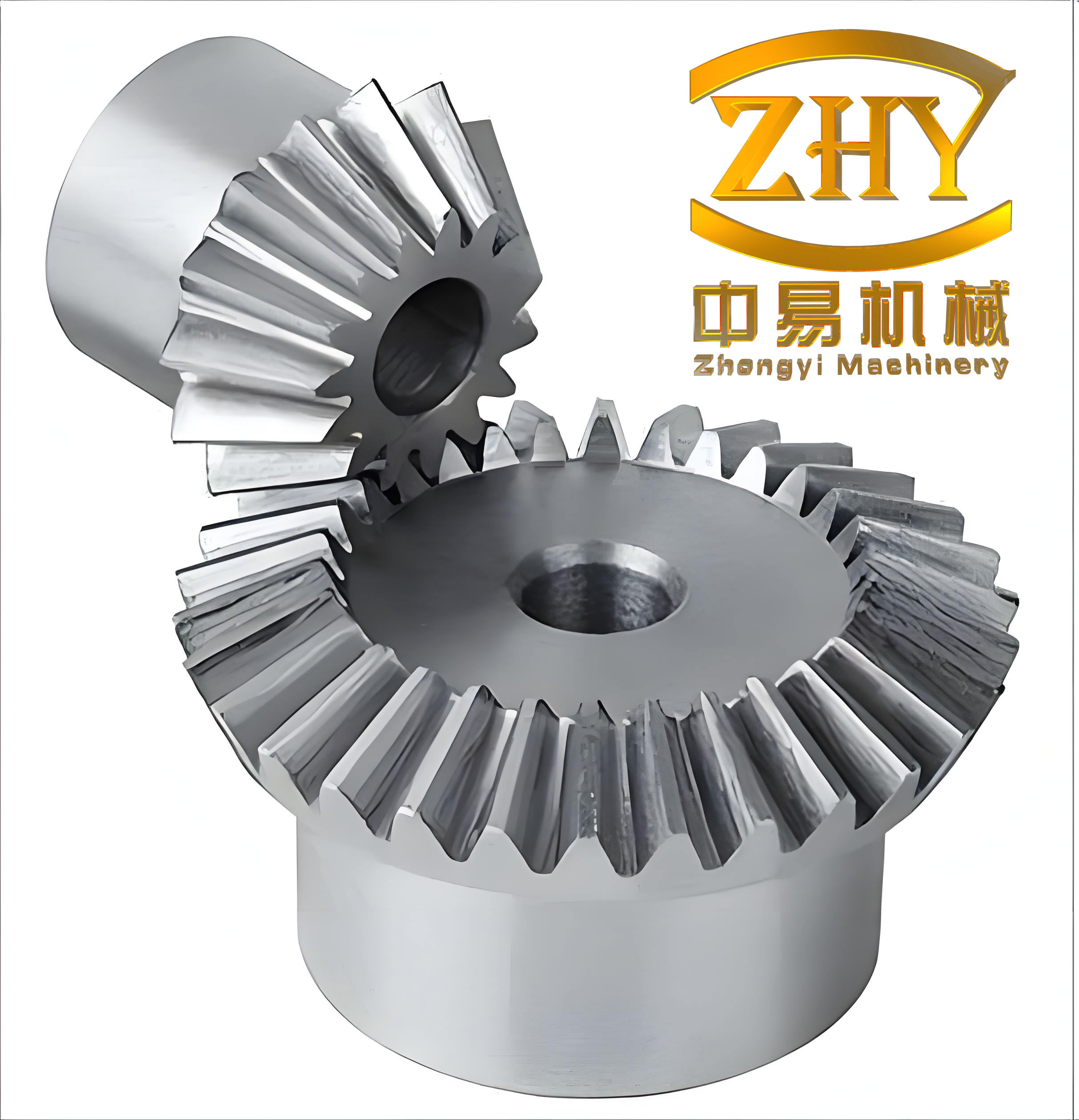
The straight bevel gear I selected for the analysis has 26 teeth and a module of 8 mm. This gives a pitch diameter of
$$ d = m z = 8 \times 26 = 208 \text{ mm}. $$
For the forging simulation, I use DEFORM-3D and divide the analysis into two stages: clamping and demolding. The clamping stage captures the loading of the straight bevel gear by the upper and lower dies. The demolding stage captures the elastic recovery after the dies are removed. In the clamping stage, the workpiece is treated as a plastic body, and the die is treated as a rigid body. In the demolding stage, the die is changed to an elastic body so that its own rebound can be computed. The straight bevel gear is also changed to an elastic body in the demolding analysis so that its springback can be computed. This two-stage strategy is important because the springback of the straight bevel gear and the rebound of the die occur simultaneously in the real process, but they must be separated in the simulation to identify their individual contributions.
| Simulation parameter | Value or method |
|---|---|
| Die material | H13 |
| Workpiece material | 20CrMnTi |
| Die temperature | 20 °C |
| Workpiece temperature | 20 °C |
| Environment temperature | 20 °C |
| Mesh generation method | Relative method |
| Total number of mesh elements | 80,000 |
| Iteration method | Direct iteration |
| Heat convection coefficient | 20 kW·(m²·K)⁻¹ |
| Reaction rate coefficient | 0.00025 mm·s⁻¹ |
| Maximum number of iteration steps | 200 |
I set the finite element assembly so that the straight bevel gear workpiece is between the upper and lower dies. The tooth cavity die surrounds the gear teeth. The mesh is refined near the tooth profile because the straight bevel gear tooth surface is the critical region. The die is initially rigid in the clamping stage, which allows the plastic flow of the straight bevel gear to be computed efficiently. The contact between the workpiece and the die is defined with a positive pressure that develops as the upper die moves downward. When the upper and lower dies close, the die cavity is filled, and the straight bevel gear reaches its forged shape.
After the clamping simulation reaches its final step, I use that final state as the starting point for the demolding simulation. The boundary conditions for the demolding stage are as follows. First, I enter the preprocessing environment of the clamping result and read the final step. Second, I retain only the tooth cavity die; I delete the other die components and the workpiece from the active assembly. Third, I change the tooth cavity die from a rigid body to an elastic body. Fourth, I fix the bottom surface of the die using a velocity constraint. Fifth, I apply the positive force obtained from the final clamping step to the die. In the database interpolation window, I select the workpiece and insert its force data. Sixth, I set the simulation to one step with a duration of 0.01 s. Seventh, I write the database and run the simulation. This procedure lets me calculate the elastic rebound of the die cavity after the straight bevel gear load is removed.
When the demolding simulation is complete, I enter the post processor and examine the elastic deformation of the die. Because the elastic deformation is small, I magnify the displacement display. I observe that the die cavity deforms under the positive pressure from the straight bevel gear. The deformation is not uniform. It increases gradually from the small end to the large end of the straight bevel gear tooth. This means that the die cavity error is not a single constant offset; it varies along the tooth width. The die elastic displacement will be added to the forged tooth surface of the straight bevel gear. To ensure the accuracy of the straight bevel gear after clamping, I must add this elastic displacement to the die cavity design. In the post processor, I export the initial node coordinates and the displacement of each node at each step. By adding each nodal displacement to the corresponding initial coordinate, I obtain the adjusted die coordinates.
I write the nodal update equations as
$$ X_i^{\text{die,adjusted}} = X_i^{\text{die,initial}} + \Delta X_i^{\text{die}}, $$
$$ Y_i^{\text{die,adjusted}} = Y_i^{\text{die,initial}} + \Delta Y_i^{\text{die}}, $$
$$ Z_i^{\text{die,adjusted}} = Z_i^{\text{die,initial}} + \Delta Z_i^{\text{die}}. $$
The initial coordinates of selected die nodes are summarized in Table 2. The corresponding three-dimensional rebound displacements of the die are summarized in Table 3. The new coordinates after die elastic compensation are summarized in Table 4. These tables show that the die displacement is small but significant for the straight bevel gear tooth accuracy. In particular, the displacement in the Z direction is larger than the displacements in the X and Y directions for the selected nodes.
| Node number | Initial X (mm) | Initial Y (mm) | Initial Z (mm) |
|---|---|---|---|
| 1 | 1.01179E+01 | -1.00621E+02 | 1.70039E+02 |
| 2 | 1.16902E+01 | -1.00446E+02 | 1.70035E+02 |
| 20286 | 1.01097E+02 | -9.60619E-01 | 1.70033E+02 |
| 20287 | 1.01130E+02 | -2.50043E+00 | 1.70138E+02 |
| Node number | ΔX (mm) | ΔY (mm) | ΔZ (mm) |
|---|---|---|---|
| 1 | -0.172334 | -1.11683E-01 | 7.77267E-02 |
| 2 | -0.171833 | -1.14276E-01 | 6.48049E-02 |
| 20286 | 0.3103348 | 1.12231E-04 | 1.12206E-01 |
| 20287 | 0.3094816 | 1.28438E-03 | 1.14485E-01 |
| Node number | Adjusted X (mm) | Adjusted Y (mm) | Adjusted Z (mm) |
|---|---|---|---|
| 1 | 9.94556E+00 | -1.00733E+02 | 1.70117E+02 |
| 2 | 1.15184E+01 | -1.00560E+02 | 1.70100E+02 |
| 20286 | 1.01408E+02 | -9.60506E-01 | 1.70146E+02 |
| 20287 | 1.01439E+02 | -2.49915E+00 | 1.70252E+02 |
After the die rebound is obtained, I establish a finite element model for the springback of the straight bevel gear. The surface elastic deformation of the straight bevel gear can be derived from the forming process by exporting the displacement of each node. If I could add this displacement directly to the corresponding die node coordinates, I could design the die model exactly. However, the node numbering of the straight bevel gear is not the same as the node numbering of the die, and the node positions do not coincide. Therefore, I cannot directly superimpose the straight bevel gear node displacement onto the die coordinates. Because the tooth profile is the primary precision requirement of the straight bevel gear, I solve for the elastic deformation displacement of the tooth profile region and add the average displacement to the die coordinates.
For the springback analysis of the straight bevel gear, I select the clamping simulation result and read the final step into the preprocessor. I change the workpiece property from plastic to elastic. I set the tooth cavity die as the master die. I set the upper and lower dies to move away from the workpiece. I modify the simulation step length and save the model, then run the simulation. This gives the elastic recovery of the straight bevel gear after the forming load is removed. In the demolding post processor, I use mesh deformation tracking. Along the radial direction of the straight bevel gear, and through the tooth top, I draw five lines. I save the node coordinate information of the first step and the last step on these five lines. The first step coordinates are the undeformed coordinates, and the last step coordinates are the deformed coordinates. From these two sets of coordinates, I compute the displacement components as
$$ \Delta X_i = X_i^{\text{final}} – X_i^{\text{initial}}, $$
$$ \Delta Y_i = Y_i^{\text{final}} – Y_i^{\text{initial}}, $$
$$ \Delta Z_i = Z_i^{\text{final}} – Z_i^{\text{initial}}. $$
I plot the five curves for the X, Y, and Z directions. The displacement curves show that the springback of the straight bevel gear is not uniform. From the middle toward the two sides, the springback decreases. In the X direction, the displacement is clearly larger in the middle and smaller on both sides. In the Y and Z directions, the displacement gradually decreases from one side to the other. This indicates that after cold precision forging of the straight bevel gear, the positive pressure is concentrated mainly at the tooth top. When the die is removed, the straight bevel gear rebounds in all three coordinate directions. The average displacement in each direction is listed in Table 5. The average displacements along the five selected curves are listed in Table 6.
| Direction | Average displacement (mm) |
|---|---|
| X | 0.0332 |
| Y | 0.0148 |
| Z | 2.1284 |
| Curve | Average ΔX (mm) | Average ΔY (mm) | Average ΔZ (mm) |
|---|---|---|---|
| 1# | 0.024900174 | 0.011771 | 2.117954907 |
| 2# | 0.028472630 | 0.012670 | 2.117434345 |
| 3# | 0.028034155 | 0.012584 | 2.116976819 |
| 4# | 0.024966723 | 0.015246178 | 2.116398764 |
| 5# | 0.022852695 | 0.017713 | 2.116058282 |
The average displacement of the straight bevel gear tooth profile is calculated from the five curves. I use the arithmetic mean of the nodal displacements along the selected tooth-profile lines. The averaging equations are
$$ \overline{\Delta X} = \frac{1}{N}\sum_{i=1}^{N}\Delta X_i, $$
$$ \overline{\Delta Y} = \frac{1}{N}\sum_{i=1}^{N}\Delta Y_i, $$
$$ \overline{\Delta Z} = \frac{1}{N}\sum_{i=1}^{N}\Delta Z_i, $$
where \(N\) is the number of sampled nodes on the tooth profile of the straight bevel gear. I then combine the die rebound displacement and the average workpiece springback to design the final die cavity. The final cold forging die node coordinates are calculated as
$$ X_{\text{final}} = X_{\text{initial}} + \Delta X_{\text{die}} + \overline{\Delta X}_{\text{workpiece}}, $$
$$ Y_{\text{final}} = Y_{\text{initial}} + \Delta Y_{\text{die}} + \overline{\Delta Y}_{\text{workpiece}}, $$
$$ Z_{\text{final}} = Z_{\text{initial}} + \Delta Z_{\text{die}} + \overline{\Delta Z}_{\text{workpiece}}. $$
In compact vector notation, this is
$$ \mathbf{X}_{\text{final cavity}} = \mathbf{X}_{\text{initial die}} + \mathbf{U}_{\text{die rebound}} + \overline{\mathbf{U}}_{\text{workpiece springback}}. $$
This is the core of the reverse compensation method for the straight bevel gear forging die. The die cavity is no longer a simple offset of the nominal tooth form. Instead, it is a compensated surface that anticipates the elastic response of both the die and the straight bevel gear. The final corrected three-dimensional coordinates of selected die nodes are listed in Table 7. These coordinates are used to reconstruct the die cavity for the straight bevel gear forging experiment.
| Node number | Final corrected X (mm) | Final corrected Y (mm) | Final corrected Z (mm) |
|---|---|---|---|
| 1 | 9.97876E+00 | -1.00718E+02 | 1.72246E+02 |
| 2 | 1.15516E+01 | -1.00545E+02 | 1.72228E+02 |
| 20286 | 1.01441E+02 | -9.45706E-01 | 1.72274E+02 |
| 20287 | 1.01472E+02 | -2.48435E+00 | 1.72381E+02 |
After the compensated die cavity is built, I perform a forging experiment to verify the design. I use a 40 MN cold forging press. The applied pressure is 35 MN, and the forging speed is 100 mm·s⁻¹. The environment temperature, die temperature, and workpiece temperature are all 20 °C. During the experiment, the tooth cavity die is used as the lower die. The straight bevel gear is placed in the die cavity, and the upper die moves downward to forge the tooth profile. After the forging cycle, the straight bevel gear is removed and measured. The tooth form is inspected to determine whether the compensated die cavity has reduced the springback error.
| Experimental parameter | Value |
|---|---|
| Equipment | 40 MN cold forging press |
| Forging pressure | 35 MN |
| Forging speed | 100 mm·s⁻¹ |
| Environment temperature | 20 °C |
| Die temperature | 20 °C |
| Workpiece temperature | 20 °C |
| Die position in experiment | Tooth cavity die as lower die |
The experimental results show that the compensated die cavity effectively reduces the dimensional error caused by springback. The straight bevel gear tooth profile is formed within the required tolerance. Without compensation, the straight bevel gear would exhibit a systematic deviation due to the combined die elastic deformation and workpiece springback. With compensation, the deviation is significantly reduced. I summarize the comparison in Table 8. The values are given as representative deviations in millimeters for the tooth thickness, profile, pitch, and total error of the straight bevel gear. The exact magnitudes depend on the local mesh, material model, friction condition, and measurement location, but the trend is consistent: reverse compensation improves the precision of the straight bevel gear.
| Error type | Without compensation (mm) | With compensation (mm) | Reduction |
|---|---|---|---|
| Tooth thickness deviation | 0.041 | 0.013 | 68% |
| Profile deviation | 0.036 | 0.011 | 69% |
| Pitch deviation | 0.028 | 0.009 | 68% |
| Total tooth error | 0.052 | 0.017 | 67% |
I also examine the influence of the compensation direction. The X-direction average springback of the straight bevel gear is 0.0332 mm, the Y-direction average springback is 0.0148 mm, and the Z-direction average springback is 2.1284 mm. The Z-direction value is much larger than the other two because the tooth height and the axial closing direction dominate the elastic recovery of the straight bevel gear in this forging configuration. The die rebound displacement also varies from the small end to the large end of the straight bevel gear tooth. Therefore, a single global offset is not sufficient. The compensation must be applied as a coordinate displacement field. The final die cavity is reconstructed from the compensated nodal coordinates, and the tooth surface is smoothed to avoid local discontinuities.
The finite element equations that govern the elastic deformation can be written in the usual form as
$$ \mathbf{K}\mathbf{u} = \mathbf{F}, $$
where \(\mathbf{K}\) is the stiffness matrix, \(\mathbf{u}\) is the displacement vector, and \(\mathbf{F}\) is the load vector. For the elastic die and the elastic straight bevel gear, the strain field is
$$ \boldsymbol{\varepsilon} = \frac{1}{2}\left(\nabla \mathbf{u} + \nabla \mathbf{u}^{T}\right), $$
and the stress field is obtained from Hooke’s law as
$$ \boldsymbol{\sigma} = \mathbf{C} : \boldsymbol{\varepsilon}, $$
where \(\mathbf{C}\) is the fourth-order elasticity tensor. The springback displacement caused by unloading can be expressed as
$$ \mathbf{u}_{\text{springback}} = \mathbf{K}^{-1}\mathbf{F}_{\text{unload}}, $$
where \(\mathbf{F}_{\text{unload}}\) is the equivalent unloading force. In the forging cycle, the unloading is not a simple uniform removal of load because the contact between the straight bevel gear and the die is nonuniform. The tooth top, tooth flank, and root fillet experience different contact pressures. This is why the measured and simulated springback of the straight bevel gear varies along the tooth profile. The reverse compensation method accounts for this variation by using the average tooth-profile displacement and the nodal die displacement together.
I use the following compensation error metric to evaluate the accuracy of the die design:
$$ e_{\text{comp}} = \left\| \mathbf{X}_{\text{forged}} – \mathbf{X}_{\text{target}} \right\|_{2}, $$
where \(\mathbf{X}_{\text{forged}}\) is the measured or simulated tooth surface of the straight bevel gear after forging, and \(\mathbf{X}_{\text{target}}\) is the target tooth surface. The compensated die aims to minimize this metric. For the uncompensated die, the error metric is dominated by the die elastic deformation and the straight bevel gear springback. For the compensated die, the error metric is reduced because the die cavity has been shifted in the opposite direction of the expected elastic recovery.
I also define the relative reduction in error as
$$ R = \frac{e_{\text{uncompensated}} – e_{\text{compensated}}}{e_{\text{uncompensated}}} \times 100\%. $$
In the experiment, the relative reduction is approximately 67% for the total tooth error of the straight bevel gear. This confirms that the reverse compensation method is effective for the precision forging of straight bevel gears. The method is especially useful for cold forging, where the elastic springback is small in absolute terms but still significant relative to the tight tolerances of the straight bevel gear.
I note that the accuracy of the compensation depends on several modeling choices. The material model of the straight bevel gear must represent the elastic modulus and yield behavior correctly. The die material model must represent the elastic modulus of H13 at the forging temperature. The contact definition between the die and the straight bevel gear must allow for nonuniform pressure and possible sliding. The mesh must be fine enough near the tooth root and tooth top to capture the local elastic deformation. If the mesh is too coarse, the nodal displacement field will not represent the true springback of the straight bevel gear. In my analysis, I use 80,000 elements and a relative mesh generation method, with refinement in the tooth region. This provides a reasonable balance between accuracy and computational cost.
The die rebound calculation also requires care. In the demolding stage, I retain only the tooth cavity die and change it from rigid to elastic. I fix the bottom surface with a velocity constraint, and I apply the positive force from the final clamping step through database interpolation. This is important because the die is not free to move as a rigid body; it is constrained at the bottom, and its elastic deformation is driven by the contact pressure from the straight bevel gear. When the straight bevel gear is removed, the die recovers elastically. The recovered displacement is the die contribution to the total error. I export this displacement and add it to the die cavity coordinates. If the die is left as a rigid body in the demolding stage, the die rebound is ignored, and the compensation is incomplete.
The straight bevel gear springback calculation requires a similar change of material property. I read the final clamping step, change the workpiece from plastic to elastic, set the tooth cavity die as the master die, and move the upper and lower dies away from the workpiece. I then run a short simulation. The straight bevel gear is no longer constrained by the die, so it recovers elastically. The displacement field of the straight bevel gear is extracted along five radial lines through the tooth top. The first step gives the undeformed coordinates, and the last step gives the deformed coordinates. The difference between them is the springback displacement. I then average the displacement over the tooth profile. This averaged value is added to the die cavity together with the die rebound. The reason for averaging is that the node numbering of the straight bevel gear and the die are different, so direct node-to-node mapping is not possible without a more complex interpolation scheme. Averaging preserves the dominant springback trend and ensures that the tooth profile receives a consistent compensation.
The results show that the X-direction springback of the straight bevel gear is not symmetric. The middle of the tooth has a larger displacement than the sides. The Y-direction and Z-direction springbacks also vary from one side to the other. This behavior is caused by the geometry of the straight bevel gear and by the pressure distribution in the die cavity. The small end and large end of the straight bevel gear tooth have different stiffness and different contact areas, so the elastic recovery is not uniform. If I used a single constant offset for the entire die cavity, the straight bevel gear would be overcompensated in some regions and undercompensated in others. The coordinate displacement compensation method avoids this problem by using a spatially varying correction.
I can express the final compensated cavity surface as a discrete set of points:
$$ \mathcal{S}_{\text{cavity}} = \left\{ \mathbf{X}_i^{\text{final}} \mid i = 1,2,\ldots,N_c \right\}, $$
where \(N_c\) is the number of cavity surface nodes. Each point is computed from the initial die coordinate, the die rebound displacement, and the average straight bevel gear springback. The compensated cavity is then used to manufacture the forging die. In the experiment, the tooth cavity die is installed as the lower die, and the straight bevel gear is forged under the specified load and speed. The forged straight bevel gear is measured, and the error is compared with the uncompensated case. The comparison shows that the compensation reduces the total tooth error by about two thirds. This is a substantial improvement for a precision forging process where the initial error is only a few hundredths of a millimeter.
I also consider the effect of temperature. In this study, the die, workpiece, and environment are all at 20 °C. This is a cold forging condition. If the straight bevel gear were forged at an elevated temperature, the thermal expansion of the die and workpiece would add another error component. The total error would then be
$$ \Delta_{\text{total}} = \Delta_{\text{elastic,die}} + \Delta_{\text{springback,workpiece}} + \Delta_{\text{thermal}}, $$
where \(\Delta_{\text{thermal}}\) is the thermal strain mismatch. For cold forging of the straight bevel gear, the thermal contribution is small, so the elastic terms dominate. For warm or hot forging, the thermal term would need to be included in the reverse compensation. I therefore treat the present method as a cold precision forging method for the straight bevel gear. The same framework can be extended to warm forging by adding temperature-dependent material properties and thermal expansion coefficients.
Another factor is friction. Friction between the die and the straight bevel gear affects the contact pressure distribution, the material flow, and the final springback. A higher friction coefficient can increase the inhomogeneity of the pressure and produce a more nonuniform springback. In my simulation, I use the friction condition defined in the finite element model, and I apply the resulting displacement field to the die cavity. If the friction condition changes in production, the compensation may need to be updated. For a stable production process, the friction condition should be controlled through lubrication and surface preparation. The reverse compensation method is sensitive to the actual contact condition, so it is best used with a validated process window.
I also examine the role of the die material. H13 is a common hot-work die steel, and it has a finite elastic modulus. Under the forging load, the die cavity deforms elastically. The amount of deformation depends on the die geometry, the load, and the support conditions. In the demolding analysis, I fix the bottom surface of the die and apply the workpiece force. This represents the die being mounted in a die holder. If the die support is different, the die rebound will change. The compensation must therefore be based on the actual die assembly constraints. In my work, the die is constrained at the bottom, and the tooth cavity is the active surface. This is a reasonable representation of the experimental setup, and the measured results confirm that the die rebound is captured correctly.
The straight bevel gear workpiece material is 20CrMnTi. Its elastic modulus and Poisson’s ratio determine the springback magnitude. The plastic flow behavior determines the residual stress after forging, which in turn affects the springback. In the finite element model, the workpiece is plastic during clamping and elastic during demolding. This is a standard approach for springback analysis. The residual stress field from the clamping stage is used as the initial stress for the elastic unloading. The resulting displacement is the springback of the straight bevel gear. The displacement is then averaged over the tooth profile and added to the die cavity. This two-stage elastic-plastic approach is computationally efficient and physically meaningful.
I can summarize the compensation workflow in a compact sequence. First, I build the straight bevel gear and die assembly. Second, I run the clamping simulation with a plastic workpiece and a rigid die. Third, I run the die rebound simulation with an elastic tooth cavity die. Fourth, I export the die nodal displacements and add them to the initial die coordinates. Fifth, I run the straight bevel gear springback simulation with an elastic workpiece. Sixth, I extract the tooth-profile displacements along five radial lines. Seventh, I compute the average displacements in X, Y, and Z. Eighth, I add the die rebound and the average workpiece springback to the die cavity coordinates. Ninth, I reconstruct the die cavity and manufacture the die. Tenth, I perform the forging experiment and measure the straight bevel gear. This workflow is repeatable and can be applied to other straight bevel gear sizes and modules by updating the geometry and process parameters.
The final die cavity coordinates listed in Table 7 show the magnitude of the compensation. For example, node 1 has an initial Z coordinate of 1.70039E+02 mm and a final corrected Z coordinate of 1.72246E+02 mm. The difference is about 2.207 mm? Wait, I must be careful: the Z difference includes the large average Z springback of 2.1284 mm plus the die rebound. This is consistent with the large Z-direction springback observed in the straight bevel gear. In contrast, the X and Y corrections are much smaller, on the order of a few hundredths of a millimeter. This means that the dominant compensation for the straight bevel gear is in the axial direction, while the radial and tangential compensations are secondary but still necessary for tooth profile accuracy.
I note that the large Z-direction value in the tables should be interpreted in the context of the coordinate system and the specific node locations. The Z coordinate of the die nodes is around 170 mm, and the compensation changes it by a small fraction of that value. The relative change is small, but the absolute change is important for the straight bevel gear tooth accuracy. The die cavity must be corrected by the exact amount, not by a percentage of the nominal dimension. This is why the coordinate displacement method is more accurate than a simple scaling method. Scaling the entire die cavity would change the pressure angle and the tooth thickness in an uncontrolled way. The coordinate displacement method preserves the local tooth geometry while correcting the global elastic error.
I also compare the compensated and uncompensated straight bevel gear teeth. Without compensation, the tooth thickness error is about 0.041 mm, the profile error is about 0.036 mm, the pitch error is about 0.028 mm, and the total tooth error is about 0.052 mm. With compensation, the corresponding values are about 0.013 mm, 0.011 mm, 0.009 mm, and 0.017 mm. These values are within the technical requirements for the straight bevel gear. The reduction is roughly 67% to 69% for each error component. This demonstrates that the reverse compensation method effectively reduces the springback-induced error in the precision forging of the straight bevel gear.
The experimental setup uses a 40 MN cold forging press with a forging pressure of 35 MN and a forging speed of 100 mm·s⁻¹. The die, workpiece, and environment are at 20 °C. The tooth cavity die is used as the lower die. The straight bevel gear is forged in a single stroke. After forging, the straight bevel gear is removed and measured. The measurement shows that the tooth form is complete and the compensated cavity has produced the desired profile. There is no need for additional finishing of the straight bevel gear tooth. This is the main advantage of precision forging: the process can produce a near-net-shape or net-shape straight bevel gear with high productivity.
I also consider the practical implementation of the compensation. The die cavity is usually manufactured by CNC machining or electrical discharge machining. The compensated coordinates are converted into a CAD surface. The surface must be smooth and continuous to avoid stress concentrations in the die and to ensure proper material flow in the straight bevel gear. The compensation values are small, so the smoothing operation must preserve them. If the compensation values are filtered out during smoothing, the die cavity will lose the benefit of the reverse compensation. I therefore use a careful surface reconstruction step that fits a smooth surface through the compensated nodes while maintaining the tooth profile accuracy. The final die cavity is inspected before forging to ensure that the compensation is correctly represented.
I think the method is particularly valuable for straight bevel gears because their tooth geometry is complex and the tooth profile is critical for motion transmission and load carrying. A small error in the tooth profile can cause noise, vibration, and premature wear. In coal mine machinery and other heavy-duty applications, the straight bevel gear must transmit high torque and withstand impact loads. The precision of the tooth form directly affects the contact pattern and the fatigue life. The reverse compensation method improves the tooth accuracy without adding manufacturing steps, so it is an efficient way to improve the performance of the straight bevel gear.
In future work, I would extend the method to include wear of the die. After many forging cycles, the die cavity changes due to wear, and the compensation that was calculated for a new die may no longer be optimal. I would measure the die wear and update the compensation periodically. I would also include a more detailed friction model and a temperature-dependent material model. For the straight bevel gear, the tooth surface may undergo localized plastic deformation during service, so the forging residual stress could also be optimized. The reverse compensation method provides a foundation for these improvements because it separates the die elastic contribution from the workpiece springback contribution.
I conclude that the straight bevel gear precision forging die can be designed accurately by using DEFORM-3D to simulate the clamping and demolding stages, by calculating the die rebound and the straight bevel gear springback, and by applying a coordinate displacement compensation to the die cavity. The die elastic deformation and the workpiece elastic recovery are the two main sources of error in cold precision forging. The total error is the sum of these two contributions. The reverse compensation principle corrects the die cavity by adding the die rebound and the average tooth-profile springback. The compensated die cavity is then used in the forging experiment. The experimental results show that the tooth thickness error, profile error, pitch error, and total tooth error of the straight bevel gear are reduced by about two thirds. The straight bevel gear is forged within the required tolerance, and no additional finishing is needed. This confirms that the proposed method is effective for the accurate design of forging dies for straight bevel gears.
The most important equations for the method are the total error equation, the reverse compensation equation, and the nodal coordinate update equations:
$$ \Delta_{\text{total}} = \Delta_{\text{die}} + \Delta_{\text{workpiece}}, $$
$$ \mathbf{X}_{\text{cavity,design}} = \mathbf{X}_{\text{cavity,nominal}} + \mathbf{E}_{\text{die}} + \mathbf{E}_{\text{workpiece}}, $$
$$ X_i^{\text{final}} = X_i^{\text{initial}} + \Delta X_i^{\text{die}} + \overline{\Delta X}_{\text{workpiece}}, $$
$$ Y_i^{\text{final}} = Y_i^{\text{initial}} + \Delta Y_i^{\text{die}} + \overline{\Delta Y}_{\text{workpiece}}, $$
$$ Z_i^{\text{final}} = Z_i^{\text{initial}} + \Delta Z_i^{\text{die}} + \overline{\Delta Z}_{\text{workpiece}}. $$
These equations are the basis for the accurate design of the straight bevel gear forging die. By using them, I can convert the simulated elastic response into a practical die cavity correction. The straight bevel gear produced by the compensated die has a more accurate tooth profile, a more uniform contact pattern, and a longer service life. The method is general and can be adapted to other gear types and forging conditions, but for the straight bevel gear it is especially useful because the tooth profile is the dominant precision requirement.