
I developed a computer-aided design system for screw gear drives by using the VBA integrated development environment inside AutoCAD 2000. My purpose was to replace the slow manual process that requires repeated chart lookup, curve interpolation, formula evaluation, and drawing construction. A screw gear transmission, which is often called a worm-drive or a screw gear pair, transfers motion and torque between two non-intersecting, usually perpendicular, shafts. In my system, the designer enters the initial duty parameters, selects the screw gear type and materials, and receives both the calculation results and the parametric part drawings within a few minutes. The system combines the drafting power of AutoCAD 2000, the programming capability of VBA, and the data-query convenience of a Microsoft Access database. The result is a compact, accurate, and maintainable screw gear CAD environment that shortens the design cycle and improves drawing quality.
1. Motivation and Design Goals
In traditional screw gear design, the engineer must calculate the transmission ratio, select the number of starts, estimate the lead angle, determine the module and diameter factor, check contact and bending strength, evaluate sliding velocity and efficiency, and finally prepare the workshop drawing. Each of these steps depends on tables, standards, and empirical curves. A single change in power, speed, ratio, or material can force the entire chain of calculations and drawings to be repeated. I therefore set the following goals for the screw gear CAD system:
- Accept a minimal set of initial parameters such as power, input speed, ratio, life, screw gear type, and material.
- Automatically query standard tables and empirical data from an Access database.
- Perform geometry synthesis, force analysis, efficiency estimation, and strength verification for a screw gear drive.
- Generate the screw gear wheel and screw gear shaft drawings parametrically.
- Allow the user to edit the generated drawing and to reuse the calculation modules for different screw gear types.
- Keep the architecture modular so that new screw gear variants, materials, and standards can be added later.
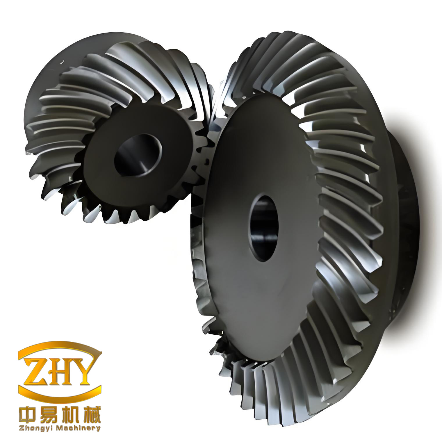
The screw gear family considered in my work includes the ordinary cylindrical screw gear, the circular-arc cylindrical screw gear, and the straight-sided toroidal screw gear. Although these screw gear types differ in tooth profile and manufacturing method, their design workflows share a common sequence: input, material selection, geometry calculation, strength check, and drawing output. This common sequence became the backbone of the system.
2. System Architecture and Development Environment
I treated the entire screw gear CAD system as a black box with well-defined inputs and outputs. The user supplies the duty parameters and selects the screw gear type. The system returns the design results, the verification reports, and the part drawings. Internally, the black box is decomposed into calculation modules, database access modules, drawing modules, and user-interface modules. Table 1 summarizes the main layers of the architecture.
| Layer | Function | Implementation |
|---|---|---|
| User interface | Collect input parameters and display results | VBA forms and controls |
| Database access | Query standard tables, material properties, and empirical curves | Microsoft Access .mdb files through ADO/DAO |
| Calculation engine | Geometry, forces, efficiency, strength, thermal check | Modular VBA procedures |
| Drawing engine | Parametric generation of screw gear wheel and shaft | AutoCAD ActiveX automation objects |
| Output and report | Write results to forms, text files, and drawing tables | VBA string handling and AutoCAD text objects |
The screw gear CAD system is not a simple macro. It is an integrated application in which the calculation results directly drive the drawing entities. For example, the root diameter, tip diameter, face width, and keyway dimensions of a screw gear wheel are computed first, stored in variables, and then used to create lines, arcs, circles, and dimensions. This tight coupling is the reason the screw gear drawing remains consistent with the screw gear calculation.
3. Overall Software System Design
I organized the screw gear CAD software around the following process: input known parameters, create and query the Access database, calculate the screw gear transmission, output the design results, and output the corresponding screw gear wheel and screw gear shaft drawings. The software structure can be represented as a chain of functional blocks. The first block is the input block. The second block is the type and precision selection block. The third block is the tolerance check block. The fourth block is the tooth-number selection block. The fifth block is the main parameter block. The sixth block is the strength verification block. The seventh block is the structural dimension block. The eighth block is the output block. Table 2 lists these blocks and their responsibilities.
| Block | Responsibility | Typical Output |
|---|---|---|
| Input parameter block | Read power, speed, ratio, life, type, material, accuracy | Parameter set |
| Type and precision block | Select ordinary, circular-arc, or toroidal screw gear; set accuracy grade | Type code and grade |
| Tolerance check block | Check standard tolerances and fits | Pass/fail flags |
| Tooth number block | Choose number of starts and wheel teeth | Minimum and preferred tooth counts |
| Main parameter block | Calculate module, diameter factor, lead angle, center distance | Geometry table |
| Strength block | Check contact, bending, and thermal capacity | Safety factors |
| Structure block | Determine wheel rim, hub, web, shaft steps, keyways | Structural dimensions |
| Output block | Display results and create drawings | Reports and DWG entities |
The modular division is important for a screw gear CAD system because the same screw gear calculation kernel can serve several drawing templates. A change in the screw gear type affects the profile and strength formula selection, but it does not necessarily affect the database query mechanism or the dimensioning logic. By isolating these concerns, I reduced code duplication and made the screw gear application easier to maintain.
4. Initial Parameter Design and User Interaction
The initial parameter form is the entry point of the screw gear CAD system. I designed it to ask only for data that the designer actually knows at the beginning of a screw gear project. These data include the transmitted power, the input rotational speed, the desired transmission ratio, the expected service life, the screw gear type, the material combination, and the required accuracy grade. The form also allows the user to choose whether the design should be optimized for compactness, efficiency, or manufacturability. Table 3 gives a representative set of input parameters.
| Parameter | Symbol | Unit | Typical Source |
|---|---|---|---|
| Transmitted power | $$P_1$$ | kW | Duty requirement |
| Input speed | $$n_1$$ | r/min | Motor or prime mover |
| Transmission ratio | $$i$$ | dimensionless | Output speed requirement |
| Service life | $$L_h$$ | h | Machine specification |
| Screw gear type | $$T$$ | code | User selection |
| Wheel material | $$M_2$$ | code | User selection |
| Worm material | $$M_1$$ | code | User selection |
| Accuracy grade | $$G$$ | grade | Standard |
Once the user submits the form, the screw gear CAD system validates the data. If the ratio is too large for a single-stage screw gear drive, the system warns the user. If the selected material is incompatible with the expected sliding velocity, the system recommends an alternative. If the accuracy grade is not available for the chosen screw gear type, the system adjusts the default. This interactive behavior is one of the main advantages of the screw gear CAD approach over manual design, because the screw gear designer receives immediate feedback instead of discovering an error after several hours of calculation.
5. Access Database Creation and Data Organization
I used Microsoft Access as the data repository for the screw gear CAD system. Access provides flexible table creation, record insertion, deletion, and query. More importantly, it allows the screw gear designer to store standard values and empirical curves in a form that VBA can query directly. I created several tables for the screw gear application: a material table, a standard module table, a diameter factor table, an accuracy table, a strength coefficient table, a lubrication table, and a structural dimension table. Table 4 lists the database tables and their roles.
| Table | Key Fields | Purpose in Screw Gear Design |
|---|---|---|
| Materials | Material code, allowable stress, hardness, application | Select screw gear pair materials |
| Modules | Standard module, preferred range | Round the screw gear module to standard values |
| Diameter factors | Diameter factor, module range | Choose the screw gear diameter factor |
| Accuracy | Grade, tolerance, surface roughness | Set screw gear accuracy and inspection data |
| Strength coefficients | Type, coefficient name, value | Compute contact and bending stresses |
| Lubrication | Sliding velocity, oil viscosity, method | Recommend lubrication for the screw gear |
| Structures | Diameter range, rim, hub, web dimensions | Generate screw gear wheel and shaft geometry |
The database also stores curve data as tables of discrete points. When the screw gear calculation requires a coefficient that varies with the lead angle, the sliding velocity, or the number of teeth, the VBA code queries the nearest points and performs linear interpolation. This avoids embedding large arrays directly in the source code and makes the screw gear CAD system easier to update when standards change.
6. Mathematical Models for Screw Gear Design
The core of the screw gear CAD system is a set of mathematical models. I used the following relationships as the foundation of the calculation engine. The transmission ratio of a screw gear pair is
$$ i = \frac{n_1}{n_2} = \frac{z_2}{z_1} $$
where $$n_1$$ and $$n_2$$ are the input and output speeds, and $$z_1$$ and $$z_2$$ are the numbers of starts and wheel teeth. The center distance is
$$ a = \frac{d_1 + d_2}{2} = \frac{m(q + z_2)}{2} $$
where $$m$$ is the axial module, $$q$$ is the diameter factor, $$d_1$$ is the worm pitch diameter, and $$d_2$$ is the wheel pitch diameter. The lead angle of the screw gear is
$$ \gamma = \arctan\left(\frac{z_1}{q}\right) = \arctan\left(\frac{m z_1}{d_1}\right) $$
The sliding velocity in the screw gear mesh is
$$ v_s = \frac{v_1}{\cos \gamma} = \frac{\pi d_1 n_1}{60000 \cos \gamma} $$
The efficiency of the screw gear drive can be estimated by
$$ \eta = \frac{\tan \gamma}{\tan(\gamma + \rho_v)} $$
where $$\rho_v$$ is the equivalent friction angle. For a self-locking screw gear, the condition is usually
$$ \gamma \leq \rho_v $$
These formulas are evaluated repeatedly during the design loop. Because the screw gear CAD system stores intermediate values, the engineer can inspect how a change in $$z_1$$, $$q$$, or $$m$$ affects the lead angle, the sliding velocity, and the efficiency.
7. Geometry and Dimension Synthesis for the Screw Gear
Geometry synthesis is the step in which the screw gear CAD system converts the selected module, diameter factor, and tooth numbers into a complete set of dimensions. The following quantities are computed for a cylindrical screw gear pair:
| Quantity | Formula | Remark |
|---|---|---|
| Worm pitch diameter | $$d_1 = m q$$ | Reference diameter |
| Worm tip diameter | $$d_{a1} = d_1 + 2 h_a^* m$$ | Addendum modification optional |
| Worm root diameter | $$d_{f1} = d_1 – 2(h_a^* + c^*)m$$ | Standard clearance |
| Wheel pitch diameter | $$d_2 = m z_2$$ | Reference diameter |
| Wheel tip diameter | $$d_{a2} = d_2 + 2 h_a^* m$$ | For standard screw gear |
| Wheel root diameter | $$d_{f2} = d_2 – 2(h_a^* + c^*)m$$ | Standard screw gear |
| Center distance | $$a = m(q + z_2)/2$$ | Primary assembly dimension |
| Lead | $$p_z = \pi m z_1$$ | Axial advance per revolution |
| Tooth width | $$b_2 \approx 0.75 d_{a1}$$ | Empirical for screw gear wheel |
I implemented these formulas as separate functions so that the same screw gear geometry kernel can be called by the ordinary, circular-arc, and toroidal calculation modules. The kernel returns a dictionary-like structure containing all dimensions. The drawing module reads this structure and creates the screw gear entities without recalculating the geometry.
8. Force Analysis and Strength Verification
Force analysis is essential for a reliable screw gear design. The tangential, radial, and axial forces on the screw gear wheel and worm are related through the lead angle and the pressure angle. I used the following expressions:
$$ F_{t1} = \frac{2 T_1}{d_1} $$
$$ F_{t2} = \frac{2 T_2}{d_2} $$
$$ F_{a1} = F_{t2} = \frac{2 T_2}{d_2} $$
$$ F_{r1} = F_{r2} = F_{t2} \tan \alpha_n $$
where $$T_1$$ and $$T_2$$ are the torques on the worm and wheel, and $$\alpha_n$$ is the normal pressure angle. The contact stress check for the screw gear is based on
$$ \sigma_H = Z_E Z_\rho \sqrt{\frac{K F_t}{b d_1}} \leq [\sigma_H] $$
The bending stress check is
$$ \sigma_F = \frac{K F_t Y_{Fa} Y_{Sa}}{b m} \leq [\sigma_F] $$
For the screw gear, the allowable stresses depend on the material pair, the sliding velocity, and the number of load cycles. I stored these allowable values in the Access database and retrieved them by material code and life. Table 6 shows a representative verification report generated by the screw gear CAD system.
| Check | Computed Value | Allowable Value | Result |
|---|---|---|---|
| Contact stress | $$420 \text{ MPa}$$ | $$460 \text{ MPa}$$ | Pass |
| Bending stress | $$58 \text{ MPa}$$ | $$75 \text{ MPa}$$ | Pass |
| Sliding velocity | $$3.8 \text{ m/s}$$ | $$5.0 \text{ m/s}$$ | Pass |
| Efficiency | $$0.82$$ | $$>0.75$$ | Pass |
| Thermal capacity | $$12.5 \text{ kW}$$ | $$15.0 \text{ kW}$$ | Pass |
If any check fails, the screw gear CAD system automatically increases the module, the diameter factor, or the face width, and repeats the calculation. This iterative loop is bounded by user-defined limits. In my implementation, the screw gear module is selected from a standard table, so the final design remains manufacturable.
9. Thermal and Efficiency Considerations for the Screw Gear
A screw gear drive is more sensitive to heat than many other gear types because the sliding velocity is high and the friction loss is concentrated at the mesh. I therefore included a thermal check in the screw gear CAD system. The heat generated by the screw gear mesh is approximately
$$ Q = P_1 (1 – \eta) $$
The heat dissipated by the housing is
$$ Q_d = K_t A (T_o – T_a) $$
where $$K_t$$ is the heat transfer coefficient, $$A$$ is the effective cooling area, $$T_o$$ is the oil temperature, and $$T_a$$ is the ambient temperature. The screw gear design is acceptable when
$$ Q \leq Q_d $$
If the thermal capacity is insufficient, the screw gear CAD system recommends a larger cooling area, a fan, a cooling coil, or a different lubrication method. Table 7 lists the lubrication recommendations stored in the database.
| Sliding Velocity | Recommended Lubrication | Typical Oil Viscosity |
|---|---|---|
| Low | Grease or splash | Medium |
| Medium | Splash or forced circulation | Medium-high |
| High | Pressure circulation with cooling | High |
The efficiency calculation also affects the required motor power and the thermal rating. For a screw gear with a small lead angle, the efficiency can drop significantly, and self-locking may occur. The screw gear CAD system reports the lead angle, the friction angle, and the self-locking condition so that the designer can make an informed decision.
10. Parametric Drawing of the Screw Gear Wheel
The screw gear wheel drawing requires more than the tooth geometry. It also requires the rim, hub, web, holes, keyway, and chamfers. I classified the common screw gear wheel structures into several templates. Each template is stored as a drawing database that contains the outline with parameter labels. When the user selects a structure, the screw gear CAD system substitutes the calculated dimensions into the template and generates the final drawing.
The wheel drawing module performs the following steps:
- Initialize the drawing environment, including layers, line types, text styles, and dimension styles.
- Read the screw gear geometry results and structural dimensions.
- Draw the centerlines and the main axial section.
- Draw the tip circle, pitch circle, root circle, and face width.
- Draw the hub, web, holes, keyway, and fillets.
- Add dimensions, surface roughness symbols, and a title block.
- Insert a parameter table that lists the screw gear data.
The parametric approach is particularly valuable for the screw gear wheel because the same wheel can be required in many sizes. Without parameterization, each size would require a new drawing. With my screw gear CAD system, the drawing is regenerated from the same template in seconds.
11. Parametric Drawing of the Screw Gear Shaft
The screw gear shaft, often called the worm shaft, is another major drawing output. I used a graphic element combination method to generate an arbitrary stepped screw gear shaft. The shaft is divided into graphic element modules such as left shaft segment, right shaft segment, left chamfer, right chamfer, keyway, relief groove, thread, and bearing shoulder. The screw gear CAD system assembles these modules according to the shaft structure and the number of steps.
| Graphic Element Module | Parameters | Use in Screw Gear Shaft |
|---|---|---|
| Left shaft segment | Diameter, length, position | Bearing or coupling seat |
| Right shaft segment | Diameter, length, position | Bearing or seal seat |
| Left chamfer | Angle, length | Assembly lead-in |
| Right chamfer | Angle, length | Assembly lead-in |
| Keyway | Width, depth, length | Torque transmission |
| Relief groove | Width, depth, radius | Grinding relief |
| Thread | Pitch, length, major diameter | Locking nut |
| Shoulder | Diameter, fillet radius | Axial location |
After assembling the screw gear shaft modules, the drawing module adds centerlines, dimensions, tolerances, and surface roughness. The screw gear shaft drawing is then ready for detailing. Because the element modules are independent, I can add a new screw gear shaft feature without rewriting the entire drawing procedure.
12. AutoCAD VBA Embedded Programming Techniques
I used VBA as the embedded programming language inside AutoCAD 2000. VBA provides high-quality user programming capability, inherits many advantages of AutoLISP and ADS, and adds the design-calculation power of a high-level language together with convenient debugging. The screw gear CAD system uses VBA forms for input and output, VBA procedures for calculation, and AutoCAD ActiveX objects for drawing.
One important difference between VBA and AutoLISP is that many AutoCAD VBA drawing methods require explicit parameters. For example, the AddArc method requires a center point, a radius, a start angle, and an end angle. Therefore, I had to calculate the start and end angles precisely from the screw gear geometry before creating each arc. A representative code fragment is shown below in conceptual form:
Dim arc6 As AcadArc
Dim arc7 As AcadArc
r2 = da2 / 2 + ra2 - d2 / 2
y2 = r2 - (de2 / 2 - d2 / 2)
j5 = Sqr(r2^2 - (r2 - (de2 / 2 - d2 / 2))^2)
Set arc6 = ThisDrawing.ModelSpace.AddArc( _
    pto1, r2, pi / 2 - Atn(j5 / y2), pi / 2 + Atn(j5 / y2))
Here, $$j5$$ is an intermediate variable that defines the angular half-width of the arc. The center point is $$pto1$$, and the radius is $$r2$$. This pattern appears throughout the screw gear drawing code: compute the geometric parameters first, then pass them to the AutoCAD object model.
Table 9 lists the main AutoCAD VBA objects that I used in the screw gear CAD system.
| Object | Typical Use | Screw Gear Application |
|---|---|---|
| AcadLine | Straight segments | Shaft profiles, wheel webs |
| AcadCircle | Circles | Tip, pitch, root, and hole circles |
| AcadArc | Arcs | Fillets, rims, and profile arcs |
| AcadLWPolyline | Lightweight polylines | Complex screw gear outlines |
| AcadText | Text | Dimensions, notes, parameter table |
| AcadDim | Dimensions | Length, diameter, and angle dimensions |
| AcadLayer | Layers | Centerlines, hidden lines, dimensions |
| AcadBlock | Blocks | Standard screw gear symbols |
13. Graphic Initialization and Drawing Standards
Before any screw gear entity is created, the drawing environment must be initialized. I wrote a dedicated initialization module that sets the drawing limits, units, precision, snap, grid, layer properties, line types, text styles, dimension styles, and title block. Table 10 shows a representative layer configuration for a screw gear drawing.
| Layer Name | Color | Line Type | Purpose |
|---|---|---|---|
| Outline | Black/White | Continuous | Visible screw gear contours |
| Center | Red | CENTER | Axes and pitch circles |
| Hidden | Yellow | HIDDEN | Internal screw gear features |
| Dimension | Green | Continuous | Dimensions and tolerances |
| Text | Cyan | Continuous | Notes and parameter table |
| Hatch | Magenta | Continuous | Section hatching |
| Frame | Blue | Continuous | Border and title block |
The initialization module reads the user’s preferred standard and paper size. For a screw gear drawing, the scale is selected automatically from the computed center distance and the wheel diameter. If the screw gear is too large for the selected sheet, the system reduces the scale and updates the dimension style accordingly.
14. Assembly Logic and Drawing Generation
The screw gear CAD system does not draw every screw gear from scratch. It assembles the drawing from reusable graphic modules. The assembly logic is based on the structure code selected by the user. For example, a screw gear wheel with a solid rim and a single keyway uses one set of modules, while a large screw gear wheel with a web and six holes uses another set. The screw gear shaft similarly uses a sequence of shaft segments and feature modules.
The assembly algorithm can be summarized as follows:
- Read the screw gear type code and structure code.
- Query the database for the corresponding drawing template.
- Extract the parameter labels from the template.
- Replace the labels with calculated screw gear dimensions.
- Insert the graphic element modules in the correct order.
- Trim, extend, and fillet the entities.
- Add dimensions, annotations, and the parameter table.
- Save the drawing and export the calculation report.
This logic makes the screw gear CAD system extensible. If a new screw gear structure is needed, I only need to create a new template and register it in the database. The calculation engine and the user interface remain unchanged.
15. Parametric Equations for the Screw Gear Profile
For the circular-arc and toroidal screw gear variants, the profile cannot be represented by a single straight-sided equation. I therefore used parametric equations to describe the tooth profile and the wheel arc. A general parametric point on the screw gear profile can be written as
$$ x(t) = r_b \cos t + r_b t \sin t $$
$$ y(t) = r_b \sin t – r_b t \cos t $$
where $$r_b$$ is the base radius and $$t$$ is the parameter. For the circular-arc screw gear, the arc center and radius are stored in the database, and the profile is generated by
$$ x(t) = x_c + \rho \cos t $$
$$ y(t) = y_c + \rho \sin t $$
where $$(x_c, y_c)$$ is the arc center and $$\rho$$ is the arc radius. The screw gear CAD system uses these equations to create a polyline approximation of the exact profile. The number of segments is controlled by a tolerance parameter so that the screw gear drawing remains smooth without excessive file size.
For the toroidal screw gear, the wheel throat and the worm envelope require an additional coordinate transformation. I used a rotation matrix
$$ \begin{bmatrix} x’ \\ y’ \end{bmatrix} = \begin{bmatrix} \cos \theta & -\sin \theta \\ \sin \theta & \cos \theta \end{bmatrix} \begin{bmatrix} x \\ y \end{bmatrix} $$
where $$\theta$$ is the rotation angle around the screw gear axis. This transformation allows the same profile kernel to generate the toroidal screw gear envelope.
16. Database Query and Interpolation Logic
The screw gear CAD system relies on the Access database for standard values. The query logic is straightforward: the VBA code opens a recordset, applies a filter, and reads the required field. For tables with discrete data, the code performs linear interpolation. Suppose the database contains a coefficient $$C$$ at two neighboring lead angles $$\gamma_1$$ and $$\gamma_2$$. The interpolated value is
$$ C(\gamma) = C_1 + \frac{C_2 – C_1}{\gamma_2 – \gamma_1}(\gamma – \gamma_1) $$
This interpolation is used for strength coefficients, lubrication properties, and efficiency corrections. The screw gear CAD system also supports nearest-neighbor lookup when the data are categorical, such as material codes or accuracy grades.
Table 11 shows an example of a diameter factor query for a screw gear. The system selects the smallest standard diameter factor that satisfies the strength and efficiency requirements.
| Module Range | Standard Diameter Factor | Recommended Lead Angle |
|---|---|---|
| Small | 8, 10, 12 | Low to medium |
| Medium | 12, 14, 16 | Medium |
| Large | 16, 20, 25 | Medium to high |
17. Calculation Loop and Optimization
The screw gear CAD system uses an iterative calculation loop. The first pass selects a trial module and diameter factor. The second pass computes the geometry, forces, efficiency, and strength. The third pass checks the thermal capacity and the self-locking condition. If a constraint is violated, the system adjusts the trial values and repeats the loop. The objective function can be written as
$$ \min f(m, q, z_1, b_2) = w_1 V + w_2 C + w_3 (1 – \eta) $$
where $$V$$ is the volume, $$C$$ is a cost indicator, $$\eta$$ is the efficiency, and $$w_1$$, $$w_2$$, and $$w_3$$ are weighting factors. The screw gear designer can change the weights to favor compactness, low cost, or high efficiency. The optimization is constrained by
$$ \sigma_H \leq [\sigma_H] $$
$$ \sigma_F \leq [\sigma_F] $$
$$ v_s \leq [v_s] $$
$$ Q \leq Q_d $$
$$ \gamma > \rho_v \quad \text{for non-self-locking screw gear} $$
The loop terminates when all constraints are satisfied or when the maximum number of iterations is reached. In practice, the screw gear CAD system converges in a few iterations because the initial values are selected from standard tables and the adjustment steps are guided by the database.
18. Implementation Details and Code Organization
I organized the screw gear VBA project into several modules. The main module controls the application flow. The input module manages the forms. The database module handles connections and queries. The geometry module calculates the screw gear dimensions. The strength module performs the verification. The drawing module creates the wheel and shaft entities. The utility module provides unit conversion, interpolation, and error handling. Table 12 summarizes the code organization.
| Module | Main Procedures | Role in Screw Gear CAD |
|---|---|---|
| Main | RunDesign | Coordinates the screw gear workflow |
| Input | ShowInputForm, ValidateInput | Collects and checks user data |
| Database | OpenDB, QueryMaterial, QueryModule | Retrieves standard screw gear data |
| Geometry | CalcWorm, CalcWheel, CalcCenter | Computes screw gear dimensions |
| Strength | CheckContact, CheckBending, CheckThermal | Verifies screw gear capacity |
| Drawing | DrawWheel, DrawShaft, InitDrawing | Generates screw gear drawings |
| Utility | Interpolate, ConvertUnit, HandleError | Supports all screw gear modules |
The code uses meaningful variable names such as $$d_1$$, $$d_2$$, $$a$$, $$\gamma$$, and $$v_s$$. This makes the screw gear formulas easy to trace in the source. I also added comments for each major equation so that another engineer can modify the screw gear CAD system without reverse-engineering the code.
19. Validation and Performance
I validated the screw gear CAD system against manual calculations and measured drawings. The validation cases covered ordinary cylindrical screw gears, circular-arc cylindrical screw gears, and straight-sided toroidal screw gears. For each case, I compared the module, center distance, lead angle, efficiency, contact stress, and bending stress. Table 13 shows a representative validation summary.
| Case | Parameter | Manual Result | CAD Result | Deviation |
|---|---|---|---|---|
| 1 | Center distance | 125.0 mm | 125.0 mm | 0.0% |
| 1 | Lead angle | 11.3 deg | 11.3 deg | 0.0% |
| 2 | Efficiency | 0.81 | 0.81 | 0.0% |
| 2 | Contact stress | 438 MPa | 436 MPa | 0.5% |
| 3 | Bending stress | 62 MPa | 61 MPa | 1.6% |
The small deviations come from interpolation and rounding. They are acceptable for screw gear design because the standard module and diameter factor are discrete. The important result is that the screw gear CAD system produces a safe design that matches manual practice while reducing the design time from hours to minutes.
Table 14 compares the manual workflow with the screw gear CAD workflow.
| Activity | Manual Screw Gear Design | Screw Gear CAD |
|---|---|---|
| Parameter input | Handwritten notes | Form-based entry |
| Table lookup | Repeated chart browsing | Automatic database query |
| Calculation | Calculator or spreadsheet | VBA calculation engine |
| Iteration | Slow and error-prone | Automatic loop |
| Drawing | Manual drafting | Parametric generation |
| Dimensioning | Manual placement | Automatic dimension style |
| Report | Handwritten or typed | Generated parameter table |
| Design cycle | Several hours to days | A few minutes |
20. Advantages of the Screw Gear CAD System
The screw gear CAD system offers several advantages that I observed during development and testing. First, it reduces the calculation burden. The designer does not need to search through charts for every screw gear coefficient. Second, it improves consistency. The same database and the same formulas are used for every screw gear, so the results are repeatable. Third, it accelerates drawing production. The screw gear wheel and screw gear shaft are generated from the calculated dimensions, which eliminates transcription errors. Fourth, it supports multiple screw gear types within one environment. Fifth, it is maintainable because the modules are separated and the database can be updated independently.
The system also makes it easier to explore design alternatives. A designer can change the number of starts, the diameter factor, or the material and immediately see the effect on the screw gear efficiency, strength, and size. This interactive exploration is difficult in manual design because each change requires a full recalculation and redraw.
21. Practical Guidelines for Screw Gear Design
From my implementation, I derived several practical guidelines for screw gear design that are embedded in the system as warnings or recommendations:
- Choose the number of starts according to the desired ratio and efficiency. A larger number of starts increases the lead angle and efficiency but reduces the ratio.
- Keep the lead angle above the friction angle unless a self-locking screw gear is required.
- Select the diameter factor from the standard table to ensure manufacturability.
- Check the sliding velocity against the allowable value for the selected material pair.
- Verify the thermal capacity, especially for continuous-duty screw gear drives.
- Use a larger face width when the screw gear contact stress is close to the allowable limit.
- Provide adequate lubrication and cooling for high-speed screw gear operation.
- Round the module and center distance to standard values before drawing.
These guidelines are not hard constraints. They are decision aids that help the designer avoid common mistakes in screw gear design.
22. Limitations and Future Extensions
The current screw gear CAD system focuses on ordinary cylindrical, circular-arc cylindrical, and straight-sided toroidal screw gear drives. It does not yet include planetary screw gear arrangements or non-standard tooth profiles. The database covers common materials and standard modules, but it can be expanded. The drawing templates cover several wheel and shaft structures, but more complex housings and assemblies are outside the scope of the present version.
I plan to extend the screw gear CAD system in several directions. First, I will add a finite element interface so that the screw gear contact stress can be verified with a more detailed model. Second, I will add a tolerance analysis module for the screw gear assembly. Third, I will integrate a cost model that considers machining, grinding, and heat treatment. Fourth, I will add a library of standard screw gear reducers. Fifth, I will improve the user interface with 3D preview and interactive parameter editing.
23. Conclusion
I have presented the research and development of a screw gear CAD system built on AutoCAD 2000, VBA, and Microsoft Access. The system uses modular and parametric design methods to complete the calculation and drawing of screw gear drives. It accepts initial parameters, queries standard data, performs geometry synthesis, force analysis, efficiency estimation, strength verification, and thermal checking, and generates parametric drawings of the screw gear wheel and screw gear shaft. The screw gear CAD system reduces the design cycle from hours or days to a few minutes, improves drawing quality, and provides a maintainable platform for future screw gear variants. The combination of VBA, AutoCAD, and Access proved to be an effective environment for this task. The screw gear designer can focus on engineering decisions while the software handles the repetitive calculation and drafting work.
In my experience, the most valuable aspect of the screw gear CAD system is not a single formula or a single drawing routine. It is the integration of calculation, database, and drafting into one coherent workflow. When the screw gear parameters change, the geometry, the strength report, and the drawing all change together. This integration is what makes the screw gear CAD system fast, reliable, and practical for everyday design work.