
I have developed a practical Excel-based engineering workbook for the design and verification of screw gears, also widely known as worm drives. My goal is to make the calculation process transparent, repeatable, and easy to modify. In many machines, screw gears transmit motion and power between non-intersecting shafts, usually at a right angle. Their compactness and high reduction ratio make them attractive, but their reliability depends on careful design. I use Excel to organize every formula, table, and decision rule so that a designer can change one input and immediately see whether the screw gears remain safe and efficient.
The design of screw gears must address contact fatigue, bending strength, efficiency, heat balance, and geometry. I treat these checks as a sequence of dependent calculations. Each calculation becomes a worksheet cell or a named range. By using data validation lists, conditional formatting, and built-in functions, I reduce manual errors and make the workbook reusable for many screw gear projects. The same workbook can be adapted to different materials, speeds, loads, and lubrication conditions.
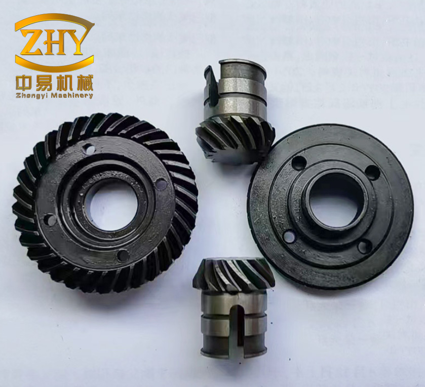
I begin with a clear design philosophy. Screw gears fail in ways similar to other gear pairs, but the sliding action between the worm and the worm wheel creates additional risks. In closed drives, the worm wheel may experience pitting and scuffing. Scuffing or adhesive wear is especially difficult to calculate precisely, so I rely on contact fatigue strength as a primary design criterion. For continuous operation, I also perform a thermal balance check because excessive heat can degrade the lubricant and damage the screw gears. Since the worm wheel teeth are generally weaker than the worm threads, I calculate the worm wheel teeth for bending and contact stresses.
Table 1: Main variables used in my screw gear workbook
| Symbol | Meaning | Typical Unit | Excel Role |
|---|---|---|---|
| \(P\) | Input power on the worm shaft | kW | Known input |
| \(n_1\) | Worm speed | r/min | Known input |
| \(n_2\) | Worm wheel speed | r/min | Known input |
| \(L_h\) | Required life | h | Calculated from years and shifts |
| \(z_1\) | Number of worm starts | — | Selected from a list |
| \(z_2\) | Number of worm wheel teeth | — | Calculated |
| \(i_{12}\) | Transmission ratio | — | Calculated |
| \(T_1\) | Worm torque | N·mm | Calculated |
| \(T_2\) | Worm wheel torque | N·mm | Calculated |
| \(\eta\) | Total efficiency | — | Calculated |
| \(m\) | Module | mm | Selected from standard values |
| \(d_1\) | Worm reference diameter | mm | Selected from standard values |
| \(d_2\) | Worm wheel reference diameter | mm | Calculated |
| \(\gamma\) | Lead angle | ° | Calculated |
| \(v_s\) | Sliding velocity | m/s | Calculated |
| \(K\) | Load factor | — | Selected |
| \(K_{HN}\) | Contact life factor | — | Calculated |
| \(K_{FN}\) | Bending life factor | — | Calculated |
| \([\sigma_H]\) | Allowable contact stress | MPa | Calculated |
| \([\sigma_F]\) | Allowable bending stress | MPa | Calculated |
I structure the workbook so that each major design step occupies a logical block. The first block stores known conditions. The second block selects materials and heat treatment. The third block calculates allowable stresses. The fourth block designs the contact strength. The fifth block checks efficiency and bending strength. The sixth block checks thermal balance. The seventh block calculates the final geometry. This order mirrors the way I think about screw gears: first understand the duty, then choose materials, then size the mesh, then verify every limit.
Table 2: Excel cell mapping in my screw gear design sheet
| Cell or Range | Content | Data Type | Notes |
|---|---|---|---|
| A1:F1 | Title: Screw Gear Design | Text | Merged and colored |
| A2:A6 | Labels for known conditions | Text | Power, speeds, life |
| B3:B6 | Known numerical inputs | Numbers | Light blue fill |
| E6 | Shift pattern | Text | Yellow fill, data validation |
| B8 | Worm wheel material | Text | Drop-down list |
| B9 | Worm material | Text | Drop-down list |
| E8:E9 | Relative sliding speed range | Text | Drop-down list |
| G9:H9 | Hardness range | Text | Drop-down list |
| D10 | Basic allowable contact stress | Number | Drop-down list |
| D11 | Basic allowable bending stress | Number | Drop-down list |
| G12 | Life in hours | Formula | \(=B6 \times 300 \times E6\) |
| D13 | Stress cycle number | Formula | \(=60 \times B5 \times D12 \times G12\) |
| D14 | Contact life factor | Formula | \((10^7/D13)^{1/8}\) |
| D16 | Bending life factor | Formula | \((10^6/D13)^{1/9}\) |
| B23 | Transmission ratio | Formula | \(=B4/B5\) |
| H23 | Worm wheel teeth | Formula | \(=E23 \times B23\) |
| G25 | Worm torque | Formula | \(=9550000 \times B3/B4\) |
| G26 | Worm wheel torque | Formula | \(=G25 \times B23 \times C25\) |
| F28 | Required \(m^2 d_1\) | Formula | \(=C28 \times G26 \times (480/(H23 \times D20))^2\) |
| C30 | Lead angle tangent | Formula | \(=E23 \times H29/J29\) |
| F30 | Lead angle in degrees | Formula | \(=180 \times \mathrm{ATAN}(C30)/(24 \times \mathrm{PI}())\) |
| C32 | Sliding velocity | Formula | \(=\mathrm{PI}() \times J29 \times B4/(60000 \times \mathrm{COS}(F30 \times \mathrm{PI}()/180))\) |
| C39 | Bending stress | Formula | \(=1.53 \times C28 \times G26 \times C38 \times \mathrm{COS}(G30 \times \mathrm{PI}()/180)/(J29 \times H23 \times H29^2)\) |
| C44 | Required heat dissipation area | Formula | \(=1000 \times B3 \times (1-C36)/(C41 \times (H42-C42))\) |
| C45 | Estimated heat dissipation area | Formula | \(=0.33 \times (C43/100)^{1.75}\) |
I use color coding to separate inputs from calculations. Yellow cells are independent variables that the designer may change. Light blue cells are known operating conditions. Purple cells contain formulas. Green cells contain decisions or messages. This visual language helps me and other users understand the workbook quickly. When I open the file, I can see immediately which values are fixed by the application and which values I am allowed to optimize.
Material selection is one of the most important steps for screw gears. The worm wheel is usually made of bronze, while the worm is made of hardened steel. The combination must resist sliding wear and provide adequate strength. I provide drop-down lists so that the user can choose from common materials without typing errors. The list includes tin bronze, lead bronze, and aluminum bronze for the worm wheel. For the worm, I include carburized steel, quenched and tempered steel, and surface-hardened steel. The relative sliding speed and hardness range are also selected from lists. These selections influence the allowable stresses and the efficiency.
Table 3: Material and heat treatment options for screw gears
| Component | Material Options | Heat Treatment or Condition | Hardness Range |
|---|---|---|---|
| Worm wheel | ZCuSn10Pb1 | Sand cast or metal mold cast | — |
| Worm wheel | ZCuSn5Pb5Zn5 | Sand cast or metal mold cast | — |
| Worm wheel | ZCuAl9Fe4Ni4 | Sand cast or metal mold cast | — |
| Worm | 20CrMnTi | Carburized and quenched | 56–62 HRC |
| Worm | 20Cr | Carburized and quenched | 56–62 HRC |
| Worm | 45 steel | High-frequency quenching | 40–50 HRC |
| Worm | 40Cr | High-frequency quenching | 50–55 HRC |
| Worm | 45 steel | Quenched and tempered | 220–250 HBW |
After material selection, I enter the basic allowable contact stress \([\sigma_{0H}]\) and the basic allowable bending stress \([\sigma_{0F}]\). These values come from standard tables and depend on the worm wheel material and casting method. I use drop-down lists to prevent incorrect values from being entered. The casting method, such as sand casting or metal mold casting, also affects the allowable stresses. Once these base values are set, the workbook calculates the actual allowable stresses by multiplying by the life factors \(K_{HN}\) and \(K_{FN}\).
Table 4: Basic allowable stress values used in my screw gear workbook
| Worm Wheel Material | Casting Method | \([\sigma_{0H}]\) (MPa) | \([\sigma_{0F}]\) (MPa) |
|---|---|---|---|
| ZCuSn10Pb1 | Sand cast | 180 | 46 |
| ZCuSn10Pb1 | Metal mold cast | 200 | 58 |
| ZCuSn10Pb1 | Centrifugal cast | 220 | 66 |
| ZCuSn5Pb5Zn5 | Sand cast | 110 | 32 |
| ZCuSn5Pb5Zn5 | Metal mold cast | 135 | 41 |
| ZCuAl9Fe4Ni4 | Sand cast | 125 | 40 |
| ZCuAl9Fe4Ni4 | Metal mold cast | 150 | 73 |
The stress cycle number \(N\) is calculated from the worm wheel speed, the number of meshing times per revolution, and the required life in hours. I use the following formula:
$$N = 60 n_2 j L_h$$
Here, \(n_2\) is the worm wheel speed in r/min, \(j\) is the number of meshing times per revolution of the worm wheel, and \(L_h\) is the life in hours. In many screw gear applications, \(j=1\). The life in hours is obtained from the number of years and the number of shifts per day. For example, if the drive operates for 10 years, 300 days per year, and one shift of 8 hours per day, then \(L_h = 10 \times 300 \times 8\). In my workbook, I store the number of years and the shift pattern, and the formula calculates \(L_h\) automatically.
The contact life factor \(K_{HN}\) and the bending life factor \(K_{FN}\) depend on \(N\). I use the following equations:
$$K_{HN} = \left(\frac{10^7}{N}\right)^{1/8}$$
$$K_{FN} = \left(\frac{10^6}{N}\right)^{1/9}$$
These formulas are valid within certain limits. If \(N\) exceeds \(25 \times 10^7\), I set \(N = 25 \times 10^7\) for the contact calculation. If \(N\) is less than \(2.6 \times 10^5\), I set \(N = 2.6 \times 10^5\). For the bending calculation, if \(N\) is greater than \(25 \times 10^7\), I set \(N = 25 \times 10^7\). If \(N\) is less than \(1 \times 10^5\), I set \(N = 1 \times 10^5\). When \(N = 10^7\), the contact life factor is 1. These rules prevent unrealistic life factors and keep the design within the range of the standard data.
Table 5: Life factor adjustment rules for screw gears
| Factor | Condition | Adjusted Value | Formula Used |
|---|---|---|---|
| \(K_{HN}\) | \(N \gt 25 \times 10^7\) | \(N = 25 \times 10^7\) | \(K_{HN} = (10^7/N)^{1/8}\) |
| \(K_{HN}\) | \(N \lt 2.6 \times 10^5\) | \(N = 2.6 \times 10^5\) | \(K_{HN} = (10^7/N)^{1/8}\) |
| \(K_{HN}\) | \(N = 10^7\) | \(K_{HN} = 1\) | Direct value |
| \(K_{FN}\) | \(N \gt 25 \times 10^7\) | \(N = 25 \times 10^7\) | \(K_{FN} = (10^6/N)^{1/9}\) |
| \(K_{FN}\) | \(N \lt 1 \times 10^5\) | \(N = 1 \times 10^5\) | \(K_{FN} = (10^6/N)^{1/9}\) |
Once the life factors are known, I calculate the allowable contact stress and the allowable bending stress:
$$[\sigma_H] = K_{HN} [\sigma_{0H}]$$
$$[\sigma_F] = K_{FN} [\sigma_{0F}]$$
These allowable stresses become the limits for the subsequent strength checks. I always compare the calculated contact stress and bending stress with these allowable values. If either calculated stress exceeds its allowable value, the workbook displays a warning message, and I adjust the module, the worm diameter, or the material until the design is safe.
The contact strength design begins with the choice of the number of worm starts \(z_1\) and the number of worm wheel teeth \(z_2\). The transmission ratio is:
$$i_{12} = \frac{n_1}{n_2}$$
I select \(z_1\) from a recommended list based on the transmission ratio. For small ratios, a larger \(z_1\) may be used. For large ratios, \(z_1\) is usually small, often 1 or 2. The number of worm wheel teeth is then:
$$z_2 = i_{12} z_1$$
I prefer \(z_2\) to be greater than 27 to ensure smooth operation and avoid undercut. The workbook calculates \(z_2\) automatically and checks that it is within a reasonable range.
The torques on the worm and worm wheel are calculated from the power and speed:
$$T_1 = 9550000 \frac{P}{n_1}$$
$$T_2 = T_1 i_{12} \eta$$
Here, \(T_1\) is in N·mm, \(P\) is in kW, and \(n_1\) is in r/min. The efficiency \(\eta\) is initially estimated from a table, and later recalculated from the lead angle and friction angle. I use an initial value between 0.7 and 0.9 for common screw gears. The workbook uses this initial efficiency to estimate \(T_2\), and then the final efficiency is used to verify the design.
The contact strength design formula for screw gears is:
$$m^2 d_1 \ge K T_2 \left(\frac{480}{z_2 [\sigma_H]}\right)^2$$
In this inequality, \(m\) is the module, \(d_1\) is the worm reference diameter, \(K\) is the load factor, \(T_2\) is the worm wheel torque, \(z_2\) is the number of worm wheel teeth, and \([\sigma_H]\) is the allowable contact stress. I select \(K\) from the range 1.1 to 1.4 depending on the load characteristics. The workbook calculates the required \(m^2 d_1\) and compares it with standard combinations of \(m\) and \(d_1\). The user then selects a standard module and worm diameter that satisfy the inequality.
Table 6: Recommended standard combinations of module and worm diameter for screw gears
| Module \(m\) (mm) | Worm Diameter \(d_1\) (mm) | \(m^2 d_1\) (mm³) | Typical Application |
|---|---|---|---|
| 2 | 22.4 | 89.6 | Light duty |
| 2.5 | 28 | 175 | Light duty |
| 3.15 | 35.5 | 352 | Medium duty |
| 4 | 40 | 640 | Medium duty |
| 5 | 50 | 1250 | Heavy duty |
| 6.3 | 63 | 2500 | Heavy duty |
| 8 | 80 | 5120 | Heavy duty |
| 10 | 90 | 9000 | Very heavy duty |
After selecting \(m\) and \(d_1\), I calculate the lead angle. The tangent of the lead angle is:
$$\tan \gamma = \frac{z_1 m}{d_1}$$
The lead angle in degrees is:
$$\gamma = \frac{180}{\pi} \arctan\left(\frac{z_1 m}{d_1}\right)$$
For screw gears, the lead angle is also equal to the helix angle of the worm wheel at the reference cylinder, so \(\gamma = \beta_2\). The workbook calculates \(\gamma\) and formats it in degrees, minutes, and seconds. This format is convenient for manufacturing and inspection.
The sliding velocity is an important parameter for efficiency and wear. I calculate it as:
$$v_s = \frac{\pi d_1 n_1}{60000 \cos \gamma}$$
Here, \(v_s\) is in m/s, \(d_1\) is in mm, and \(n_1\) is in r/min. The workbook compares \(v_s\) with the selected relative sliding speed range. If \(v_s\) is within the range, the message “Speed suitable” appears. If not, the message “Speed not suitable, please recalculate” appears. This immediate feedback helps me avoid selecting materials or lubrication that are incompatible with the actual sliding speed.
The efficiency of screw gears is calculated from the lead angle and the equivalent friction angle. The equivalent friction angle \(\rho_v\) depends on the sliding velocity and the materials. I select \(\rho_v\) from a table and enter it in degrees and minutes. The workbook converts it to decimal degrees:
$$\rho_v = \text{degrees} + \frac{\text{minutes}}{60}$$
The meshing efficiency is:
$$\eta_1 = \frac{\tan \gamma}{\tan(\gamma + \rho_v)}$$
The total efficiency includes the meshing efficiency and the losses in bearings and churning:
$$\eta = \eta_1 \eta_2 \eta_3$$
where \(\eta_2 \eta_3\) is typically between 0.95 and 0.97. I enter this value from a drop-down list or as a default. The workbook then recalculates \(T_2\) using the updated efficiency. This iterative process is easy to perform in Excel because the formulas update automatically.
Table 7: Efficiency parameters for screw gears
| Parameter | Symbol | Typical Range | Source |
|---|---|---|---|
| Lead angle | \(\gamma\) | 5° to 30° | Calculated |
| Equivalent friction angle | \(\rho_v\) | 0.5° to 5° | Table based on \(v_s\) and materials |
| Meshing efficiency | \(\eta_1\) | 0.5 to 0.95 | Calculated |
| Bearing and churning efficiency | \(\eta_2 \eta_3\) | 0.95 to 0.97 | Selected |
| Total efficiency | \(\eta\) | 0.5 to 0.9 | Calculated |
The bending strength of the worm wheel teeth is checked using the following formula:
$$\sigma_F = \frac{1.53 K T_2 Y_{F2} \cos \gamma}{d_1 z_2 m^2}$$
Here, \(Y_{F2}\) is the tooth form factor for the worm wheel, which depends on the equivalent number of teeth. I select \(Y_{F2}\) from a table and enter it in a yellow cell. The workbook calculates \(\sigma_F\) and compares it with the allowable bending stress \([\sigma_F]\). If \(\sigma_F \lt [\sigma_F]\), the message “Bending strength sufficient” appears. Otherwise, the message “Bending strength insufficient, please recalculate” appears. I then increase the module, change the material, or adjust the geometry.
Thermal balance is critical for continuously operating screw gears. The heat generated by friction must be dissipated through the housing. The required heat dissipation area is:
$$A \ge \frac{1000 P (1-\eta)}{k_s (t_1 – t_0)}$$
In this formula, \(P\) is the input power in kW, \(\eta\) is the total efficiency, \(k_s\) is the heat transfer coefficient in W/(m²·°C), \(t_1\) is the allowable lubricating oil temperature, and \(t_0\) is the ambient air temperature. I use \(k_s = 10\) to \(17\) W/(m²·°C) for natural convection. The ambient temperature is usually 20°C. The lubricating oil temperature is usually limited to 70–90°C. The workbook calculates the required area and compares it with an estimated area:
$$A \approx 0.33 \left(\frac{a}{100}\right)^{1.75}$$
Here, \(a\) is the center distance in mm:
$$a = \frac{d_1 + m z_2}{2}$$
If the estimated area is smaller than the required area, the workbook displays “Heat dissipation area less than required, please add cooling fins or other cooling measures.” Otherwise, it displays “Heat dissipation area sufficient.” This check prevents overheating and ensures reliable operation of the screw gears.
Table 8: Thermal balance parameters for screw gears
| Parameter | Symbol | Typical Value or Range | Unit |
|---|---|---|---|
| Heat transfer coefficient | \(k_s\) | 10–17 | W/(m²·°C) |
| Ambient air temperature | \(t_0\) | 20 | °C |
| Lubricating oil temperature | \(t_1\) | 70–90 | °C |
| Required heat dissipation area | \(A\) | Calculated | m² |
| Estimated heat dissipation area | \(A\) | Calculated | m² |
Finally, I calculate the geometry of the screw gears. The addendum coefficient \(h_a^*\) is normally 1, and the clearance coefficient \(c^*\) is normally 0.2. I enter these values in yellow cells. The worm and worm wheel dimensions are then calculated with simple formulas:
$$d_{a1} = d_1 + 2 h_a^* m$$
$$d_{f1} = d_1 – 2 (h_a^* + c^*) m$$
$$p_{a1} = \pi m$$
$$b_1 \ge (11 + 0.06 z_2) m$$
$$d_2 = m z_2$$
$$d_{a2} = d_2 + 2 h_a^* m$$
$$d_{f2} = d_2 – 2 (h_a^* + c^*) m$$
$$d_{e2} \le d_{a2} + \frac{6 m}{z_1 + 2}$$
$$b_2 \le 0.75 d_{a1}$$
These dimensions are essential for manufacturing drawings and for checking interference. The workbook calculates each value and displays it with the correct unit. The user can then take the “take \(b_2 =\)” cell and enter a standard width that satisfies the inequality.
Table 9: Geometry formulas for screw gears in my Excel workbook
| Dimension | Formula | Unit | Excel Expression |
|---|---|---|---|
| Worm addendum circle diameter | \(d_{a1} = d_1 + 2 h_a^* m\) | mm | \(=J29+2*C47*H29\) |
| Worm dedendum circle diameter | \(d_{f1} = d_1 – 2 (h_a^* + c^*) m\) | mm | \(=J29-2*(C47+F47)*H29\) |
| Worm axial pitch | \(p_{a1} = \pi m\) | mm | \(=H29*\mathrm{PI}()\) |
| Worm threaded length | \(b_1 \ge (11 + 0.06 z_2) m\) | mm | \(=(11+0.06*H23)*H29\) |
| Worm wheel reference diameter | \(d_2 = m z_2\) | mm | \(=H29*H23\) |
| Worm wheel addendum circle diameter | \(d_{a2} = d_2 + 2 h_a^* m\) | mm | \(=C52+2*C47*H29\) |
| Worm wheel dedendum circle diameter | \(d_{f2} = d_2 – 2 (h_a^* + c^*) m\) | mm | \(=C52-2*(C47+F47)*H29\) |
| Worm wheel outer diameter | \(d_{e2} \le d_{a2} + \frac{6 m}{z_1 + 2}\) | mm | \(=C53+6*H29/(E23+2)\) |
| Worm wheel width | \(b_2 \le 0.75 d_{a1}\) | mm | \(=0.75*C48\) |
I also use Excel functions to automate decisions and warnings. The IF function is used for speed suitability, bending strength, and thermal balance. For example, the speed check is:
$$=\mathrm{IF}(v_s \lt v_{s,\max}, \text{“Speed suitable”}, \text{“Speed not suitable, please recalculate”})$$
The bending check is:
$$=\mathrm{IF}(\sigma_F \lt [\sigma_F], \text{“Bending strength sufficient”}, \text{“Bending strength insufficient, please recalculate”})$$
The thermal check is:
$$=\mathrm{IF}(A_{\text{estimated}} \lt A_{\text{required}}, \text{“Heat dissipation area less than required, please add cooling fins”}, \text{“Heat dissipation area sufficient”})$$
These messages make the workbook interactive. I do not need to remember every limit; the workbook tells me whether the current design is acceptable. I can then adjust the yellow input cells and watch the messages update in real time.
Table 10: Excel functions used in my screw gear design workbook
| Function | Purpose | Example |
|---|---|---|
| Data Validation | Create drop-down lists for materials, speeds, and hardness | List: ZCuSn10Pb1, ZCuSn5Pb5Zn5, ZCuAl9Fe4Ni4 |
| Comments | Store standard tables and notes in cells | Basic allowable stress table in a comment |
| IF | Display suitability messages | \(=\mathrm{IF}(C32 \lt E8,\text{“Speed suitable”},\text{“Speed not suitable”})\) |
| ATAN | Calculate lead angle from tangent | \(=\mathrm{ATAN}(C30)\) |
| PI | Return the value of \(\pi\) | \(=\mathrm{PI}()\) |
| COS | Calculate cosine of the lead angle | \(=\mathrm{COS}(F30*\mathrm{PI}()/180)\) |
| LEFT and MID | Parse degrees and minutes from text | \(=\mathrm{LEFT}(C33,1)+\mathrm{MID}(C33,2,2)/60\) |
| Conditional Formatting | Highlight warnings and key results | Green fill for acceptable results |
I have also created an example calculation to demonstrate how the workbook behaves. Suppose the input power is 3 kW, the worm speed is 1440 r/min, the worm wheel speed is 72 r/min, and the required life is 10 years with one shift per day. The transmission ratio is \(i_{12}=20\). I select \(z_1=2\), so \(z_2=40\). The worm torque is \(T_1=9550000 \times 3 / 1440 \approx 19896\) N·mm. With an initial efficiency of 0.8, the worm wheel torque is \(T_2 \approx 19896 \times 20 \times 0.8 \approx 318336\) N·mm. If the allowable contact stress is 180 MPa and \(K=1.2\), the required \(m^2 d_1\) is:
$$m^2 d_1 \ge 1.2 \times 318336 \times \left(\frac{480}{40 \times 180}\right)^2 \approx 1.2 \times 318336 \times 0.00444 \approx 1696 \text{ mm}^3$$
I can then select \(m=5\) mm and \(d_1=50\) mm, because \(m^2 d_1 = 25 \times 50 = 1250\), which is less than 1696. So I try \(m=6.3\) mm and \(d_1=63\) mm, giving \(m^2 d_1 = 39.69 \times 63 \approx 2500\) mm³, which satisfies the requirement. The workbook performs this comparison automatically and highlights the acceptable standard combination.
Next, the lead angle is:
$$\tan \gamma = \frac{2 \times 6.3}{63} = 0.2$$
$$\gamma \approx 11.31^\circ$$
The sliding velocity is:
$$v_s = \frac{\pi \times 63 \times 1440}{60000 \cos 11.31^\circ} \approx 4.86 \text{ m/s}$$
If the selected friction angle is \(1^\circ 30’\), then \(\rho_v = 1.5^\circ\). The meshing efficiency is:
$$\eta_1 = \frac{\tan 11.31^\circ}{\tan(11.31^\circ + 1.5^\circ)} \approx \frac{0.2}{0.227} \approx 0.88$$
With \(\eta_2 \eta_3 = 0.96\), the total efficiency is \(\eta \approx 0.845\). This value is higher than the initial estimate, so the workbook updates \(T_2\) to about \(19896 \times 20 \times 0.845 \approx 336000\) N·mm. The contact design is then rechecked. This iteration is simple because Excel recalculates instantly.
The bending stress is calculated with \(Y_{F2}\) selected from a table. Suppose \(Y_{F2}=2.2\). Then:
$$\sigma_F = \frac{1.53 \times 1.2 \times 336000 \times 2.2 \times \cos 11.31^\circ}{63 \times 40 \times 6.3^2} \approx \frac{1.53 \times 1.2 \times 336000 \times 2.2 \times 0.9806}{63 \times 40 \times 39.69} \approx 41.2 \text{ MPa}$$
If the allowable bending stress is 46 MPa, the bending strength is sufficient. If not, I increase the module or choose a stronger material. The workbook displays the result immediately.
For thermal balance, suppose \(k_s = 15\) W/(m²·°C), \(t_1 = 80\)°C, \(t_0 = 20\)°C, and \(\eta = 0.845\). The required area is:
$$A \ge \frac{1000 \times 3 \times (1 – 0.845)}{15 \times (80 – 20)} = \frac{465}{900} \approx 0.517 \text{ m}^2$$
The center distance is:
$$a = \frac{63 + 6.3 \times 40}{2} = 157.5 \text{ mm}$$
The estimated area is:
$$A \approx 0.33 \left(\frac{157.5}{100}\right)^{1.75} \approx 0.33 \times 1.99 \approx 0.657 \text{ m}^2$$
Since \(0.657 \gt 0.517\), the heat dissipation area is sufficient. If the estimated area were smaller, I would add cooling fins or a fan. This thermal check is essential for continuous-duty screw gears.
The geometry calculations then produce all the dimensions needed for manufacturing. For the example, \(d_2 = 6.3 \times 40 = 252\) mm. With \(h_a^*=1\) and \(c^*=0.2\), the worm addendum circle diameter is \(d_{a1} = 63 + 2 \times 1 \times 6.3 = 75.6\) mm. The worm dedendum circle diameter is \(d_{f1} = 63 – 2 \times 1.2 \times 6.3 = 47.88\) mm. The worm axial pitch is \(p_{a1} = \pi \times 6.3 \approx 19.79\) mm. The threaded length is \(b_1 \ge (11 + 0.06 \times 40) \times 6.3 = 13.4 \times 6.3 \approx 84.42\) mm. The worm wheel dimensions are similarly calculated. The workbook organizes all these results in a clear table.
I have found that using Excel for screw gear design offers several advantages. First, it reduces arithmetic errors because every formula is entered once and reused. Second, it makes iteration fast; changing one input updates all dependent results. Third, it documents the design logic; the cell comments and drop-down lists preserve standard values and decision rules. Fourth, it creates a reusable technical file that can be applied to many projects. I can save the workbook as a template and start each new screw gear design by entering only the known conditions.
For screw gears, the most important checks are contact strength, bending strength, efficiency, and thermal balance. I always perform these checks in the order described. If any check fails, I adjust the module, the worm diameter, the number of starts, or the material until all checks pass. The Excel workbook makes this process systematic and transparent. I can also add charts to visualize the relationship between module, center distance, and efficiency. For example, I can plot efficiency versus lead angle or contact stress versus module. These charts help me choose the best compromise between size, cost, and performance.
In summary, I use Excel to transform the design of screw gears from a manual, error-prone task into a structured, interactive calculation. The workbook contains input cells, formula cells, decision cells, and result tables. It uses data validation to ensure correct material and speed selections. It uses IF functions to display warnings. It uses standard formulas for stress cycles, life factors, allowable stresses, contact strength, bending strength, efficiency, thermal balance, and geometry. By following this approach, I can design reliable screw gears efficiently and confidently. The same framework can be extended to other mechanical transmissions, but for screw gears it provides a particularly clear and practical solution.