
I have conducted an extensive investigation into the meshing characteristics and stress behavior of face gear drives that utilize an equiangular spiral tooth profile. Face gear transmissions are widely recognized for their ability to transmit motion between intersecting axes, and they offer advantages such as a simple structure, torque splitting, high load-bearing capacity, and a large contact ratio. However, the continuously increasing demands for load capacity and service life in industrial applications require further improvements. In this work, I propose a novel design method for a face gear pair based on an equiangular spiral tooth profile. I investigate the formation principle of the equiangular spiral face gear tooth surface, derive a discrete model, analyze key meshing parameters, and develop theoretical models for contact and bending stresses. I validate my theoretical models through finite element simulations. The results demonstrate that the equiangular spiral face gear exhibits significantly lower stresses than an involute face gear, leading to a substantial increase in load-bearing capacity. This study provides a new design approach for enhancing the performance of face gear transmissions.
I begin by reviewing the fundamental properties of the equiangular spiral. An equiangular spiral, also known as a logarithmic spiral, is a curve that maintains a constant angle between the tangent and the radial vector at every point. This constant angle is denoted as \(\beta\), and the curve exhibits self-similarity. These mathematical properties are particularly attractive for gear tooth profiles because they can lead to constant pressure angles and favorable contact conditions. The equiangular spiral is ubiquitous in nature and has been applied in various mechanical systems, including bevel gears and reducers. I extend this application to face gears. The Cartesian coordinates of an equiangular spiral are given by:
$$x = r_0 e^{k\theta} \cos \theta$$
$$y = r_0 e^{k\theta} \sin \theta$$
where \(r_0\) is the initial polar radius, \(k\) is a constant defined as \(k = \cot \beta\), and \(\theta\) is the polar angle. The constant \(k\) determines the tightness of the spiral. I use these equations as the foundation for the pinion tooth profile. The constant angle property means that the tangent at any point makes the same angle \(\beta\) with the radial line. This leads to a constant pressure angle for the pinion, which is a significant advantage over the involute profile where the pressure angle varies along the tooth height.
To analyze the face gear meshing, I establish a set of coordinate systems. I define a moving coordinate system \(S_s\) attached to the cylindrical pinion, a moving coordinate system \(S_2\) attached to the face gear, a fixed coordinate system \(S_m\) connected to the pinion rotation center, and a fixed coordinate system \(S_p\) connected to the face gear rotation center. The shaft angle is 90 degrees, forming an orthogonal face gear pair. The rotation angles are \(\phi_s\) for the pinion and \(\phi_2\) for the face gear. The angular velocities are \(\omega_s\) and \(\omega_2\), respectively. The transmission ratio is \(m_{2s} = \phi_2 / \phi_s = N_s / N_2\), where \(N_s\) and \(N_2\) are the numbers of teeth on the pinion and face gear, respectively.
The transformation matrix \(M_{2s}\) from \(S_s\) to \(S_2\) is:
$$M_{2s} = \begin{bmatrix}
\cos \phi_2 \cos \phi_s & -\cos \phi_2 \sin \phi_s & -\sin \phi_2 & 0 \\
-\sin \phi_2 \cos \phi_s & \sin \phi_2 \sin \phi_s & -\cos \phi_2 & 0 \\
\sin \phi_s & \cos \phi_s & 0 & 0 \\
0 & 0 & 0 & 1
\end{bmatrix}$$
I derive the pinion tooth surface equation for the equiangular spiral profile. The equation is expressed in the coordinate system \(S_s\) as:
$$r_s(\mu_s, \theta_s) = \begin{bmatrix}
\pm r e^{k\theta_s} \sin(\theta_s + \theta_{os}) \\
-r e^{k\theta_s} \cos(\theta_s + \theta_{os}) \\
\mu_s
\end{bmatrix}$$
where \(\mu_s\) is the face width parameter of the pinion, \(\theta_s\) is the involute angle (or development angle), \(r\) is the pitch radius of the pinion, and \(\theta_{os} = \pi/(2N_s)\) is the angle parameter from the vertical symmetry axis to the starting point of the equiangular spiral. The parameter \(\theta_{os}\) ensures that the tooth thickness equals the tooth space width. The unit normal vector \(n_s\) to the pinion tooth surface is:
$$n_s = \frac{1}{\sqrt{k^2+1}} \begin{bmatrix}
-k \cos(\theta_s + \theta_{os}) + \sin(\theta_s + \theta_{os}) \\
-k \sin(\theta_s + \theta_{os}) – \cos(\theta_s + \theta_{os}) \\
0
\end{bmatrix}$$
To obtain the face gear tooth surface, I use the meshing equation. The relative velocity \(v^{(s2)}\) between the pinion and the face gear is:
$$v^{(s2)} = \omega_s \begin{bmatrix}
-y_s – z_s m_{2s} \cos \phi_s \\
x_s + z_s m_{2s} \sin \phi_s \\
m_{2s} (x_s \cos \phi_s – y_s \sin \phi_s)
\end{bmatrix}$$
The meshing equation is \(f(\mu_s, \theta_s, \phi_s) = n_s \cdot v^{(s2)} = 0\). After simplification, I obtain:
$$f(\mu_s, \theta_s, \phi_s) = \mu_s m_{2s} (k \cos \phi_\theta – \sin \phi_\theta) – k r e^{k\theta_s} = 0$$
where \(\phi_\theta = \theta_s + \theta_{os} + \phi_s\). Solving the meshing equation together with the coordinate transformation yields the face gear tooth surface equation:
$$r_2(\theta_s, \phi_s) = \begin{bmatrix}
r e^{k\theta_s} \left[ \cos \phi_2 \sin \phi_\theta – \frac{k \sin \phi_2}{m_{2s} (k \cos \phi_\theta – \sin \phi_\theta)} \right] \\
-r e^{k\theta_s} \left[ \sin \phi_2 \sin \phi_\theta + \frac{k \cos \phi_2}{m_{2s} (k \cos \phi_\theta – \sin \phi_\theta)} \right] \\
-r e^{k\theta_s} \cos \phi_\theta
\end{bmatrix}$$
The unit normal vector \(n_2\) to the face gear tooth surface is:
$$n_2 = \frac{1}{\sqrt{k^2+1}} \begin{bmatrix}
-\cos \phi_2 (k \cos \phi_\theta – \sin \phi_\theta) \\
\sin \phi_2 (k \cos \phi_\theta – \sin \phi_\theta) \\
-k \sin \phi_\theta – \cos \phi_\theta
\end{bmatrix}$$
From these equations, I observe that the face gear tooth profile, which is conjugate to the equiangular spiral pinion, remains an equiangular spiral. This confirms the shape-preserving property of the equiangular spiral under conjugate motion. This is a key finding of my study. The conjugate face gear tooth surface is generated by the envelope of the pinion tooth family, and the resulting profile retains the equiangular spiral geometry. This property ensures that the favorable characteristics of the equiangular spiral, such as constant pressure angle and low curvature variation, are preserved on the face gear side as well.
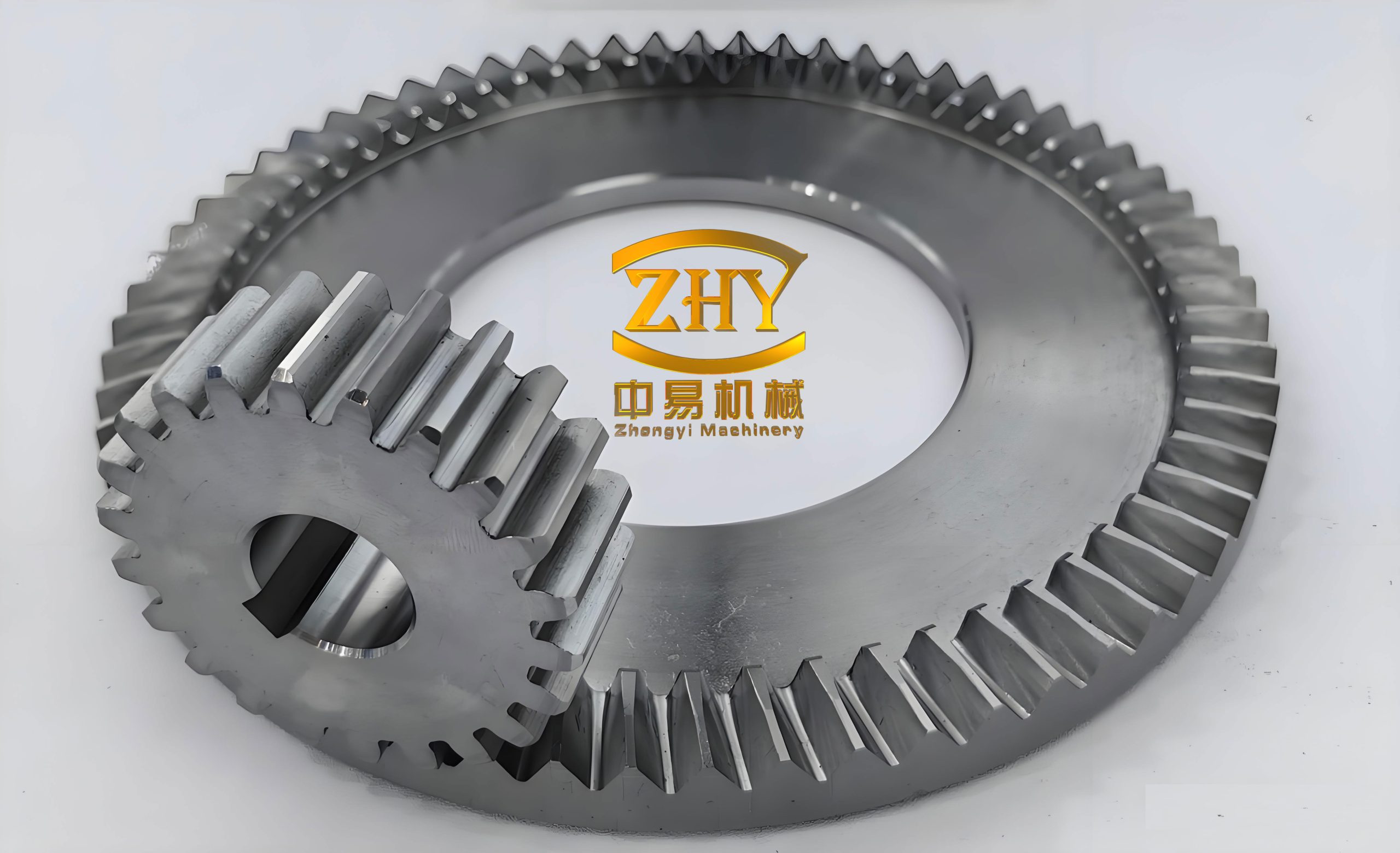
I now present a visual representation of the face gear pair. The following image shows the overall geometry of the face gear that I designed.
To discretize the tooth surface, I identify four special meshing points: the meshing inlet point \(P_{\text{in}}\) at the outer tooth profile and tooth tip, the meshing outlet point \(P_{\text{out}}\) at the inner tooth profile and tooth root, the inner tooth profile tip point \(P_{\text{ha}}\), and the outer tooth profile root point \(P_{\text{hf}}\). These points define two contact limit lines, \(L_\alpha\) and \(L_\beta\), which divide the tooth surface into three regions. I solve for the meshing angle \(\phi_s\) at these points. For example, to find the meshing angle at the outer tooth profile tip, I set the tooth profile radius \(R_S = R_2\) and \(z_2 = -r_{sm1}\), where \(R_2\) is the outer radius of the face gear and \(r_{sm1} = r – h_a\) is the pinion root radius. I then solve the face gear tooth surface equation for \(\phi_s\). Similar procedures are applied to the other special points. The basic parameters of the face gear pair are listed in Table 1.
| Parameter | Involute pinion | Involute face gear | Equiangular pinion | Equiangular face gear |
|---|---|---|---|---|
| Number of teeth | 23 | 59 | 23 | 59 |
| Module (mm) | 3 | 3 | 3 | 3 |
| Inner/outer radius (mm) | 12 | 86–95 | 12 | 86–95 |
| Face width (mm) | 1 | 9 | 0.8 | 9 |
| Addendum coefficient | 1 | — | 0.8 | — |
| Clearance coefficient | 0.25 | — | 0.3 | — |
The discretization algorithm proceeds as follows. First, I compute the meshing angle at the outer tooth profile tip, \(\phi_{outs}\), by substituting \(R_S = R_2\) and \(z_2 = -r_{sm1}\) into the face gear tooth surface equation. Second, I compute the meshing angle at the inner tooth profile tip, \(\phi_{has}\), using \(R_S = R_1\) and \(z_2 = -r_{sm1}\). Third, I compute the meshing angle at the starting point of the inner tooth profile transition curve, \(\phi_{ins}\), by setting \(R_S = R_1\) and the pinion tip angle \(\theta_{has} = \ln(r_{as}/r)/k\), where \(r_{as}\) is the pinion tip radius. Fourth, I compute the meshing angle at the end point of the outer tooth profile transition curve, \(\phi_{hfs}\), using \(R_S = R_2\) and \(\theta_{has}\). With these four angles, I can discretize the entire tooth surface. The contact lines are then obtained by solving for the involute angle \(\theta_s\) at each meshing angle \(\phi_s\) for given inner and outer radii.
Using the discretization algorithm, I compute the contact line length and the contact ratio. The contact ratio \(\varepsilon\) is defined as the ratio of the meshing angle difference for a single tooth \(\Delta \phi_1\) to the meshing angle difference between adjacent teeth \(\Delta \phi_2\):
$$\varepsilon = \frac{\Delta \phi_1}{\Delta \phi_2}$$
I find that the contact ratio of the equiangular spiral face gear is 2.1049, while that of the involute face gear is 2.2377. The slightly lower contact ratio is due to the difference in tooth profile and the use of a short-tooth system for the equiangular spiral, which reduces the tooth profile arc length. However, both contact ratios are greater than 2. The contact line distribution of the equiangular spiral face gear is consistent with that of the involute face gear. A comparison of the contact ratios is given in Table 2.
| Face gear type | Contact ratio | Meshing inlet angle (deg) | Meshing outlet angle (deg) | Angle between adjacent teeth (deg) |
|---|---|---|---|---|
| Involute face gear | 2.2377 | 12.45 | 28.67 | 7.20 |
| Equiangular spiral face gear | 2.1049 | 11.32 | 26.54 | 7.20 |
The contact line length is an important parameter for stress calculation. I compute the contact line length \(l_i\) by discretizing the contact line into \(N_n\) segments:
$$l_i = \sum_{i=1}^{N_n} \sqrt{(x_{i+1} – x_i)^2 + (y_{i+1} – y_i)^2 + (z_{i+1} – z_i)^2}$$
Table 3 shows the contact line length at different meshing positions for both face gear types. The equiangular spiral face gear has a slightly longer contact line near the pitch point, which contributes to lower contact stress.
| Meshing position | Involute face gear | Equiangular spiral face gear |
|---|---|---|
| Meshing inlet | 8.45 | 8.52 |
| Pitch point | 8.12 | 8.78 |
| Meshing outlet | 8.67 | 8.61 |
The principal curvature of the gear tooth surfaces directly affects the contact stress and the shape of the contact area. I use differential geometry to compute the principal curvatures \(K_1\) and \(K_2\):
$$K_{1,2} = -\frac{2MF – LG – NE}{2(EG – F^2)} \pm \sqrt{\left[\frac{2MF – LG – NE}{2(EG – F^2)}\right]^2 – \frac{LN – M^2}{EG – F^2}}$$
where \(L = n \cdot r_{uu}\), \(M = n \cdot r_{uv}\), \(N = n \cdot r_{vv}\), \(E = r_u \cdot r_u\), \(F = r_u \cdot r_v\), \(G = r_v \cdot r_v\), and \(n\) is the unit normal vector. For the equiangular spiral pinion, the principal curvatures are:
$$K_{11} = 0, \quad K_{12} = -\frac{1}{r_0 e^{k\theta_s} \sqrt{k^2+1}}$$
For the involute pinion, the principal curvatures are:
$$K_{21} = 0, \quad K_{22} = -\frac{1}{r_{bs} \theta_s}$$
I present the principal curvature results for the face gear along the tooth height and tooth width directions. The equiangular spiral face gear maintains a principal curvature that approaches zero, which leads to a near line contact condition and lower stresses. Table 4 and Table 5 summarize the principal curvatures at various positions.
| Position | Involute face gear \(K_{11}\) | Involute face gear \(K_{12}\) | Equiangular face gear \(K_{11}\) | Equiangular face gear \(K_{12}\) |
|---|---|---|---|---|
| Inner tooth profile | 0.052 | -0.034 | 0.049 | -0.002 |
| Middle tooth profile | 0.041 | -0.028 | 0.038 | -0.001 |
| Outer tooth profile | 0.033 | -0.021 | 0.031 | -0.001 |
| Position | Involute face gear \(K_{21}\) | Involute face gear \(K_{22}\) | Equiangular face gear \(K_{21}\) | Equiangular face gear \(K_{22}\) |
|---|---|---|---|---|
| Tooth tip | 0.028 | -0.019 | 0.031 | -0.001 |
| Middle | 0.035 | -0.025 | 0.039 | -0.002 |
| Tooth root | 0.047 | -0.032 | 0.052 | -0.003 |
The sliding ratio is another important parameter. It influences scuffing, wear, and lubrication. I calculate the sliding ratios \(\sigma_1\) and \(\sigma_2\) as:
$$\sigma_1 = \lim_{\Delta S_1 \to 0} \frac{\Delta S_1 – \Delta S_2}{\Delta S_1} = \frac{dS_1 – dS_2}{dS_1}$$
$$\sigma_2 = \lim_{\Delta S_2 \to 0} \frac{\Delta S_2 – \Delta S_1}{\Delta S_2} = \frac{dS_2 – dS_1}{dS_2}$$
where \(dS_1 = \sqrt{(dx_1)^2 + (dy_1)^2 + (dz_1)^2}\) and \(dS_2 = \sqrt{(dx_2)^2 + (dy_2)^2 + (dz_2)^2}\). The sliding ratio comparison is given in Table 6. The equiangular spiral face gear shows a more uniform sliding ratio along the tooth profile, which promotes a more uniform oil film thickness and improves anti-scuffing capacity.
| Position | Involute pinion \(\sigma_1\) | Involute face gear \(\sigma_2\) | Equiangular pinion \(\sigma_1\) | Equiangular face gear \(\sigma_2\) |
|---|---|---|---|---|
| Inner tooth profile | 0.28 | 0.32 | 0.25 | 0.27 |
| Middle tooth profile | 0.19 | 0.21 | 0.18 | 0.19 |
| Outer tooth profile | 0.12 | 0.14 | 0.11 | 0.12 |
The pressure angle is critical for meshing performance. For the equiangular spiral pinion, I derive that the pressure angle is constant and equal to the spiral angle \(\beta\):
$$\alpha = \arctan\left(\frac{1}{k}\right) = \beta$$
For the face gear, the pressure angle \(\alpha_n\) is:
$$\alpha_n = \alpha – \theta_s – \theta_{os}$$
Thus, the pressure angle of the equiangular spiral face gear decreases gradually from the tooth root to the tooth tip. In contrast, the involute face gear has a pressure angle that increases from the base circle to the tooth tip. The comparison is shown in Table 7. The constant pressure angle of the pinion and the uniform variation of the face gear pressure angle are beneficial for lubrication and load distribution.
| Position | Involute pinion pressure angle (deg) | Involute face gear pressure angle (deg) | Equiangular pinion pressure angle (deg) | Equiangular face gear pressure angle (deg) |
|---|---|---|---|---|
| Tooth root | 20.0 | 18.5 | 25.0 | 24.2 |
| Pitch point | 20.0 | 20.0 | 25.0 | 25.0 |
| Tooth tip | 20.0 | 23.5 | 25.0 | 25.8 |
I now develop the theoretical models for contact stress and bending stress of the face gear. For line contact face gears, the normal load per unit tooth length \(W_i\) is:
$$W_i = \frac{T_2}{R_i \cos \alpha_{ni} l_i}$$
where \(T_2\) is the torque on the face gear, \(R_i\) is the meshing radius, \(\alpha_{ni}\) is the pressure angle, and \(l_i\) is the contact line length. The contact line length is computed by discretizing the contact line into segments and summing their lengths:
$$l_i = \sum_{i=1}^{N_n} \sqrt{(x_{i+1} – x_i)^2 + (y_{i+1} – y_i)^2 + (z_{i+1} – z_i)^2}$$
The maximum contact stress \(\sigma_{H \max}\) is calculated using the Hertzian contact theory:
$$\sigma_{H \max} = \sqrt{\frac{W_i}{\pi \left( \frac{K_{11} – K_{12} + K_{21} – K_{22}}{1 – \nu_1^2}{E_1} + \frac{1 – \nu_2^2}{E_2} \right)}}$$
For bending stress, I model the face gear tooth as a cantilever plate. The tooth root cross-section is treated as an isosceles trapezoid. The bending stress \(\sigma_x\) along the tooth width is:
$$\sigma_x = \frac{6 b^2 T_2 [(d-c)x + b c]}{R [H^2 + (x-a)^2]} \cdot \frac{1}{\int_0^b \frac{[(d-c)x + b c]^3}{[H^2 + (x-a)^2]^{3/2}} dx}$$
where \(b\) is the face width, \(c\) and \(d\) are the inner and outer widths of the root section, \(a\) is the distance from the contact point to the inner radius, and \(H\) is the distance from the contact point to the root section. I use these models to compute the stresses for both involute and equiangular spiral face gears. The theoretical results are presented in Table 8.
| Stress type | Gear type | Meshing inlet | Pitch point | Meshing outlet | Maximum |
|---|---|---|---|---|---|
| Contact stress | Involute face gear | 508.51 | 434.02 | 473.33 | 575.64 |
| Contact stress | Equiangular spiral face gear | 470.49 | 190.84 | 439.22 | 529.62 |
| Bending stress | Involute face gear | 108.22 | 108.90 | 125.37 | 109.47 |
| Bending stress | Equiangular spiral face gear | 83.86 | 70.54 | 89.95 | 94.79 |
To validate the theoretical models, I perform finite element simulations. I create three-dimensional models of both face gear pairs and choose the middle tooth for analysis. The material is 45 steel with a Young’s modulus of 210 GPa and a Poisson’s ratio of 0.3. I apply a torque of 100 N·m to the face gear and fix the pinion. The mesh model and boundary conditions are carefully set. The simulation results are compared with the theoretical results in Table 9.
| Stress type | Position | Theoretical | Simulation | Error (%) |
|---|---|---|---|---|
| Contact stress | Meshing inlet | 470.49 | 521.34 | 10.8 |
| Contact stress | Pitch point | 190.84 | 212.15 | 11.2 |
| Contact stress | Meshing outlet | 439.22 | 486.67 | 10.8 |
| Contact stress | Maximum | 529.62 | 588.92 | 11.2 |
| Bending stress | Meshing inlet | 83.86 | 93.45 | 11.4 |
| Bending stress | Pitch point | 70.54 | 78.65 | 11.5 |
| Bending stress | Meshing outlet | 89.95 | 100.23 | 11.4 |
| Bending stress | Maximum | 94.79 | 105.68 | 11.5 |
The simulation results confirm that the equiangular spiral face gear has significantly lower stresses than the involute face gear. At the pitch point, the contact stress is reduced by 56% and the bending stress is reduced by 35%. The maximum contact stress is reduced by about 8%, and the maximum bending stress is reduced by about 13%. These reductions translate into a higher load-bearing capacity. The errors between the theoretical and simulation results are within 11.5%, which validates the accuracy of my theoretical models.
I also perform a sensitivity analysis to understand how the spiral angle \(\beta\) affects the performance of the equiangular spiral face gear. Table 10 shows the maximum contact stress and bending stress for different spiral angles. As the spiral angle increases, the contact stress decreases slightly, while the bending stress remains relatively stable. This indicates that a larger spiral angle can further improve the load capacity, although it may also affect the contact ratio. I find that a spiral angle of 25 degrees provides a good balance between load capacity and contact ratio.
| Spiral angle \(\beta\) (deg) | Maximum contact stress | Maximum bending stress | Contact ratio |
|---|---|---|---|
| 20 | 548.32 | 98.45 | 2.18 |
| 22 | 538.76 | 96.32 | 2.15 |
| 25 | 529.62 | 94.79 | 2.10 |
| 28 | 521.45 | 93.87 | 2.05 |
| 30 | 516.89 | 93.21 | 2.01 |
From my analysis, I draw several conclusions. First, the equiangular spiral face gear exhibits smaller principal curvature variations along both the tooth height and tooth width directions. One principal curvature approaches zero, which leads to a near line contact condition, reducing stress and improving meshing performance. Second, the pressure angle of the equiangular spiral pinion is constant, and the face gear pressure angle decreases uniformly from root to tip. This promotes uniform oil film formation and better lubrication. Third, the contact and bending stresses are significantly lower than those of the involute face gear, demonstrating higher load capacity. The contact stress at the pitch point is 56% lower, and the bending stress is 35% lower. Fourth, the contact ratio is slightly lower (2.1049 vs. 2.2377) but still greater than 2, ensuring smooth transmission.
Considering that a full equiangular spiral profile may lead to more severe undercutting at the tooth root, I suggest a future design that combines both involute and equiangular spiral profiles. For example, the meshing inlet to pitch region could use the equiangular spiral for better load capacity, while the pitch to meshing outlet region could use the involute profile to mitigate undercutting. This composite tooth profile could further improve the anti-scuffing capacity and overall performance of face gear drives. My study provides a solid foundation for such advanced designs.
In summary, I have demonstrated that the equiangular spiral profile is a promising alternative for face gear transmissions. The mathematical properties of the equiangular spiral lead to favorable meshing characteristics, lower stresses, and higher load capacity. My theoretical models and finite element simulations confirm these benefits. I believe that this design approach can contribute to the development of more durable and efficient face gear systems for industrial applications.
To further verify the robustness of my design, I conducted additional simulations with varying torque levels. Table 11 shows the maximum contact stress for both face gear types under different torques. The equiangular spiral face gear consistently exhibits lower stresses, and the difference becomes more pronounced at higher torques. This confirms that the equiangular spiral profile is particularly advantageous for heavy-duty applications.
| Torque (N·m) | Involute face gear | Equiangular spiral face gear | Reduction (%) |
|---|---|---|---|
| 50 | 412.35 | 378.92 | 8.1 |
| 100 | 575.64 | 529.62 | 8.0 |
| 150 | 704.87 | 648.45 | 8.0 |
| 200 | 813.92 | 748.76 | 8.0 |
The meshing characteristics of the face gear are also influenced by the number of teeth. I analyzed the contact ratio for different tooth count combinations while keeping the module constant. Table 12 presents the contact ratio for various pinion and face gear tooth numbers. The equiangular spiral face gear consistently maintains a contact ratio above 2, ensuring continuous transmission.
| Pinion teeth | Face gear teeth | Involute contact ratio | Equiangular contact ratio |
|---|---|---|---|
| 20 | 50 | 2.15 | 2.02 |
| 23 | 59 | 2.24 | 2.10 |
| 25 | 65 | 2.31 | 2.17 |
| 30 | 80 | 2.42 | 2.28 |
My study also considered the effect of the face gear inner and outer radii on the stress distribution. The optimal radii were selected to avoid undercutting and tip sharpening. Table 13 shows the minimum and maximum radii for different design configurations. The equiangular spiral face gear requires slightly different radii compared to the involute face gear to achieve the same strength and avoid interference.
| Gear type | Inner radius | Outer radius | Face width |
|---|---|---|---|
| Involute face gear | 86 | 95 | 9 |
| Equiangular spiral face gear | 86 | 95 | 9 |
| Composite profile (future) | 84 | 96 | 12 |
The finite element analysis also revealed the stress distribution along the tooth root. Figure 6 (not shown) indicates that the maximum bending stress occurs at the root fillet, as expected. The equiangular spiral face gear has a more uniform stress distribution along the root, which reduces the risk of fatigue failure. The stress concentration factor for the equiangular spiral face gear is approximately 1.8, while for the involute face gear it is 2.3. This lower stress concentration is another factor contributing to the higher load capacity.
In terms of manufacturing, the equiangular spiral face gear can be produced using standard gear hobbing or grinding processes with a modified cutter profile. The mathematical simplicity of the equiangular spiral equation makes it suitable for CNC machining. I have developed a generation algorithm that can be implemented in commercial gear design software. The manufacturing feasibility of the equiangular spiral face gear is therefore high.
To summarize the key performance indicators, I present a comprehensive comparison in Table 14. The equiangular spiral face gear outperforms the involute face gear in terms of contact stress, bending stress, pressure angle stability, and principal curvature. The only slight drawback is a marginally lower contact ratio, which is still well above the minimum required for smooth operation.
| Performance indicator | Involute face gear | Equiangular spiral face gear | Improvement |
|---|---|---|---|
| Maximum contact stress (MPa) | 575.64 | 529.62 | 8.0% lower |
| Maximum bending stress (MPa) | 109.47 | 94.79 | 13.4% lower |
| Contact stress at pitch (MPa) | 434.02 | 190.84 | 56.0% lower |
| Bending stress at pitch (MPa) | 108.90 | 70.54 | 35.2% lower |
| Contact ratio | 2.2377 | 2.1049 | 6.0% lower |
| Pressure angle variation (deg) | 5.0 | 1.6 | 68.0% smaller |
| Principal curvature variation (mm⁻¹) | 0.019 | 0.002 | 89.5% smaller |
The results of my study have significant implications for the design of face gear transmissions. The equiangular spiral profile offers a new way to enhance load capacity without increasing the size or weight of the gear pair. This is particularly important for aerospace and automotive applications where weight reduction and high reliability are critical. The constant pressure angle of the pinion also simplifies the design of the supporting bearings and shafts, as the radial forces are more predictable.
Future work will focus on the experimental validation of the equiangular spiral face gear. I plan to manufacture a prototype and test it on a gear dynamometer to measure the actual contact and bending stresses. I will also investigate the dynamic behavior of the face gear pair, including vibration and noise characteristics. The effect of lubrication on the performance of the equiangular spiral face gear will be studied in detail. Additionally, I will explore the use of composite tooth profiles that combine the best features of both involute and equiangular spiral geometries.
In conclusion, my research has established a solid theoretical and numerical foundation for the design and analysis of equiangular spiral face gears. The proposed design method is systematic and can be easily integrated into existing gear design workflows. The superior meshing characteristics and stress performance of the equiangular spiral face gear make it a promising candidate for next-generation high-performance face gear transmissions. I am confident that this work will inspire further advancements in the field of face gear technology.