
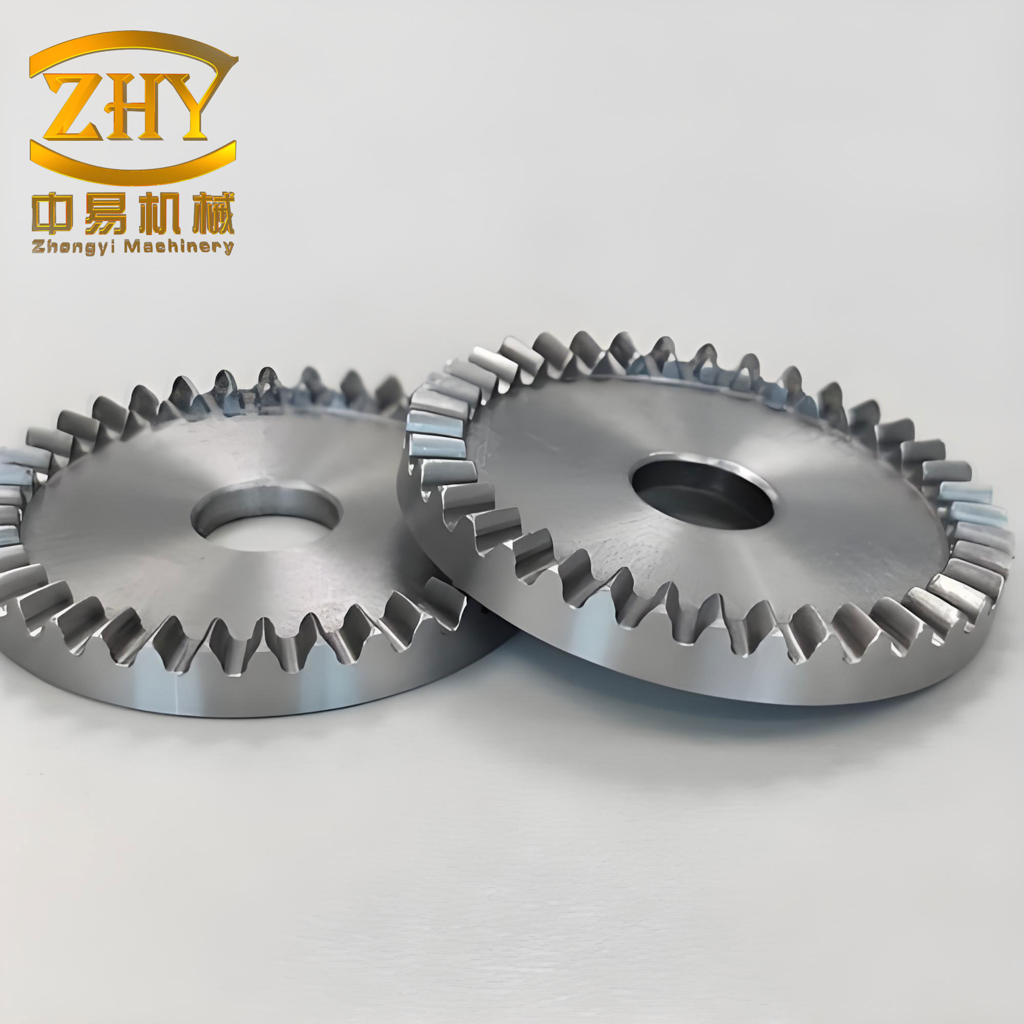
I investigated a face gear transmission system because a face gear offers compact structure, high load capacity, favorable torque splitting, and large transmission ratio. These advantages make the face gear attractive for high-speed and heavy-load applications such as aviation transmission systems and heavy vehicles. However, the same severe operating conditions that make the face gear useful also make its tooth surface vulnerable to scuffing, adhesive wear, and fatigue damage. I therefore developed a laser-cladding route to strengthen the face gear tooth surface. My approach used a nickel-based self-fluxing alloy as a transition layer and a NiCr-Cr3C2 cermet as the hard wear-resistant top layer. The transition layer reduced the mismatch between the soft metallic substrate and the hard ceramic-bearing coating. I then studied grinding of the cladded face gear tooth surface to restore geometry, reduce roughness, and improve surface integrity. The overall aim was to increase tooth surface hardness, improve wear resistance at medium and high temperatures, and extend the service life of the face gear.
I first analyzed the interaction between the laser and the materials. When the laser beam reaches the substrate and powder, the energy is partly reflected and partly absorbed. For a material that does not transmit the laser, the energy balance is
$$
E_0 = E_r + E_a
$$
where E0 is the incident laser energy, Er is the reflected energy, and Ea is the absorbed energy. I defined the reflectivity R and absorptivity A as
$$
1 = R + A,\qquad R=\frac{E_r}{E_0},\qquad A=\frac{E_a}{E_0}
$$
For metallic materials, the absorptivity depends on resistivity, laser wavelength, and the number of outer electron shells. A simplified expression that I used for discussion is
$$
A = 0.1457\sqrt{\frac{\rho}{\lambda}} + 0.09\frac{\rho}{\lambda} – 1.0\times 10^{-6}N
$$
where rho is electrical resistivity, lambda is laser wavelength, and N is the number of outer electron shells. I noted that a shorter wavelength and a higher temperature generally increase absorptivity. The ceramic phase in the cermet also absorbs near-infrared laser radiation more effectively than a polished metal surface. Therefore, a fiber laser with a wavelength near 1.07 micrometers was suitable for cladding NiCr-Cr3C2 on steel.
I also considered the penetration depth of the laser. For a Gaussian beam, the power density at the center of the spot can be written as
$$
I(0,0)=\frac{2P}{\pi R_b^2}
$$
where P is laser power and Rb is the beam radius. For a material with absorptivity A, the power density at depth z is
$$
I(z)=I_0\exp(-Az)
$$
The temperature field is affected by thermal conductivity, laser spot size, and scanning speed. I used these relations to select process windows rather than arbitrary values. The maximum penetration depth before excessive dilution or vaporization can be approximated by
$$
z_{\max}=\frac{\ln T_d – \ln T_c}{A}
$$
where Td and Tc are characteristic temperatures related to melting and vaporization. I used this reasoning to avoid too low dilution, which causes weak bonding, and too high dilution, which degrades the coating.
For cladding quality, I controlled four main parameters: laser power, scanning speed, powder feed rate, and overlap ratio. I also controlled layer number. The ideal single-track cross section should have a suitable thickness H, width W, penetration depth h, and contact angle theta. The contact angle is a convenient indicator of wetting and interfacial bonding. I used
$$
\theta = 180^\circ – 2\arctan\left(\frac{H}{W}\right)
$$
For good multi-track overlap and low porosity, I aimed for theta between 120 degrees and 150 degrees, which corresponds approximately to
$$
0.14 < \frac{H}{W} < 0.28
$$
The dilution rate eta is another important quantity. I expressed it as
$$
\eta = \frac{h}{H+h}
$$
I preferred a dilution range of about 8 to 15 percent for the transition layer. This range gives metallurgical bonding while keeping the coating composition close to the designed powder. A too-small dilution can produce cracks or poor bonding, while a too-large dilution can reduce hardness and wear resistance.
For the substrate, I selected 20Cr2Ni4A, a common high-strength steel for heavy-duty gears. I machined plates with dimensions of 130 mm by 50 mm by 10 mm. Before cladding, I ground the surface with abrasive paper, removed rust and oxide, and cleaned the plates with anhydrous ethanol. The chemical composition of the substrate is summarized in the following table.
| Element | C | Cr | Mn | Si | P | S | Ni |
|---|---|---|---|---|---|---|---|
| Mass fraction (%) | 0.21 | 1.35 | 2.20 | 0.38 | 0.02 | 0.02 | 3.46 |
For the transition layer, I used Ni45 powder with a particle size of about 200 mesh. Ni45 has moderate hardness, good toughness, and good impact resistance. Its working temperature is generally below 650 degrees Celsius, and its melting point is about 950 degrees Celsius. The composition of the Ni45 powder is given in the next table.
| Element | C | Cr | B | Si | Fe | Ni |
|---|---|---|---|---|---|---|
| Mass fraction (%) | 0.06 | 7.52 | 2.20 | 3.50 | 3.62 | Balance |
For the hard top layer, I used NiCr-Cr3C2 cermet powder. The powder contained 25 mass percent NiCr and 75 mass percent Cr3C2. Its particle size was between about 325 and 500 mesh. The theoretical hardness of the cermet is approximately HV0.2 800 to HV0.2 1000, corresponding to about HRC 64 to 70. Its working temperature can reach about 850 degrees Celsius, and its melting point is about 1810 degrees Celsius. The chemical composition of the NiCr and Cr3C2 constituents is listed below.
| Constituent | Ni | Cr | C | Si | Fe | O |
|---|---|---|---|---|---|---|
| Ni-Cr (mass %) | 79.50 | 19.60 | – | 0.64 | 0.31 | 0.25 |
| Cr3C2 (mass %) | – | 84.72 | 13.40 | 0.01 | – | 0.13 |
I used a fiber laser, a six-axis robot, a coaxial powder feeder, and a laser cladding head. The robot positioned the cladding head with high repeatability. The powder feeder delivered two powder streams synchronously, which allowed me to deposit the transition layer and the cermet layer without changing the setup. The cladding head had four coaxial nozzles and a maximum laser power of about 6 kW. I used a spot diameter of 2 mm and a positive defocus of 15 mm in the single-track experiments.
After cladding, I cut cross sections with wire electrical discharge machining, mounted them, ground them with 600 to 1000 grit papers, and polished them. I etched the cross sections with a mixture of HF, HNO3, and H2O in a volume ratio of 2:4:7 for about 20 seconds. I then cleaned the samples in an ultrasonic bath for 10 minutes and dried them. I examined microstructure with scanning electron microscopy, phase constitution with X-ray diffraction, hardness with a Vickers microhardness tester, and friction and wear with a high-temperature reciprocating tribometer.
In the single-track experiments, I varied laser power from 300 to 700 W, scanning speed from 1 to 5 mm/s, and powder feed rate from 7 to 12 g/min. I kept the overlap ratio and other conditions constant when I studied one parameter. The results showed clear trends. I summarized the main geometric effects in the following table.
| Parameter | Change | Effect on thickness H | Effect on width W | Effect on contact angle theta |
|---|---|---|---|---|
| Scanning speed | Increase | Decreases | Decreases | Increases |
| Powder feed rate | Increase | Increases | Slightly decreases | Decreases |
| Laser power | Increase | Slight overall decrease, local recovery | Increases | Increases |
I explained these trends through the energy and mass balance. When scanning speed increases, the laser-material interaction time decreases. Less powder is melted, and less energy enters the substrate, so both H and W decrease. When powder feed rate increases, more particles enter the melt pool, so H increases. At the same time, the powder stream acts as a coolant and shields part of the laser energy, so W decreases slightly. When laser power increases, the melt pool becomes wider because more energy enters the substrate. The effect on H is more complex because a wider melt pool spreads the same powder over a larger area, while a higher power melts more powder. The two effects compete.
I found that for Ni45 on 20Cr2Ni4A, a suitable single-track window was laser power of 600 W, scanning speed of 3 mm/s, and powder feed rate of 7 g/min. Under these conditions, the contact angle was about 125 degrees. This angle is within the preferred range and favors good overlap and low porosity. I used this window as the basis for the transition layer on the face gear.
Hardness is a key indicator for wear resistance. I measured hardness along the depth of the cladding. In general, I observed that increasing laser power decreased hardness. Higher laser power produced a larger melt pool, slower cooling, and coarser microstructure. For the cermet layer, excessive temperature also promoted decomposition or partial dissolution of Cr3C2, which reduced the amount of intact hard phase. Increasing scanning speed and powder feed rate produced a more complex trend: hardness first decreased and then increased, but the overall tendency was upward. Faster scanning and higher powder feed rate reduced the thermal input per unit mass, refined the grains, and helped retain hard ceramic particles. A summary of hardness trends is given below.
| Parameter | Change | Overall hardness trend | Reason |
|---|---|---|---|
| Laser power | Increase | Decrease | Coarser microstructure, possible Cr3C2 decomposition |
| Scanning speed | Increase | First decrease, then increase; overall increase | Finer grains, less thermal damage |
| Powder feed rate | Increase | First decrease, then increase; overall increase | Lower powder temperature, finer structure, retained hard phase |
| Overlap ratio | Increase | Weak effect | Little change in local composition; smoother surface at high overlap |
| Number of layers | Increase | Increase, then saturate | Reheating and grain growth; cracking risk rises |
Overlap ratio affected surface finish and hardness uniformity. I tested 20, 30, 40, and 50 percent overlap. A larger overlap produced a smoother surface but reduced deposition efficiency. A smaller overlap produced a rougher surface. For hardness distribution along depth, 20 and 30 percent overlap gave relatively stable values. I selected 30 percent overlap for the face gear because it balanced surface smoothness and efficiency. The following table summarizes the overlap observations.
| Overlap ratio (%) | Surface finish | Hardness uniformity | Deposition efficiency |
|---|---|---|---|
| 20 | Rough | Relatively stable | High |
| 30 | Acceptable | Relatively stable | Acceptable |
| 40 | Smoother | More fluctuation | Lower |
| 50 | Smoothest | More fluctuation | Lowest |
Layer number also mattered. I deposited one, two, three, and four NiCr-Cr3C2 layers over a Ni45 transition layer. Hardness generally increased with layer number, but the increase saturated after three layers. More importantly, cracking susceptibility increased markedly. Three layers showed small cracks, and four layers showed large cracks. Therefore, I limited the coating design to two NiCr-Cr3C2 layers on top of the Ni45 transition layer.
I used an orthogonal experiment to optimize the NiCr-Cr3C2 layer thickness. The factors and levels are shown in the following table.
| Level | Scanning speed Vs (mm/s) | Laser power P (W) | Powder feed rate Vf (g/min) |
|---|---|---|---|
| 1 | 2 | 500 | 9 |
| 2 | 3 | 600 | 10 |
| 3 | 4 | 700 | 11 |
The measured thickness results are listed below.
| Run | Vs (mm/s) | P (W) | Vf (g/min) | Thickness H (mm) |
|---|---|---|---|---|
| 1 | 2 | 500 | 11 | 0.37 |
| 2 | 2 | 600 | 9 | 0.26 |
| 3 | 2 | 700 | 10 | 0.30 |
| 4 | 3 | 500 | 10 | 0.34 |
| 5 | 3 | 600 | 11 | 0.44 |
| 6 | 3 | 700 | 9 | 0.23 |
| 7 | 4 | 500 | 9 | 0.45 |
| 8 | 4 | 600 | 10 | 0.41 |
| 9 | 4 | 700 | 11 | 0.36 |
I performed a range analysis. The range values were Rpower = 0.097, Rspeed = 0.090, and Rfeed = 0.077. Therefore, laser power had the strongest influence on thickness, followed by scanning speed, and then powder feed rate. The best combination in this experiment was laser power of 500 W, scanning speed of 3 mm/s, and powder feed rate of 11 g/min. I selected these parameters for the NiCr-Cr3C2 top layer on the face gear. The range analysis is summarized below.
| Index | Vs (mm/s) | P (W) | Vf (g/min) | H (mm) |
|---|---|---|---|---|
| K1 | 1.110 | 1.221 | 0.939 | – |
| K2 | 1.161 | 1.011 | 1.050 | – |
| K3 | 0.891 | 0.930 | 1.170 | – |
| R | 0.090 | 0.097 | 0.077 | – |
With the optimized parameters, I examined the microstructure of the Ni45/NiCr-Cr3C2 coating. The cross section showed dense bonding among the substrate, the Ni45 transition layer, and the NiCr-Cr3C2 top layer. In the top layer, I observed rod-like and dendritic crystals rich in Cr and C. I also found black spherical or blocky particles. Energy-dispersive spectroscopy indicated that these particles were Cr3C2 hard phase. Their composition was approximately 64.42 mass percent Cr and 8.58 mass percent C, corresponding to 48.32 atomic percent Cr and 27.64 atomic percent C. The dispersion of Cr3C2 increased hardness and wear resistance. At the interface between the NiCr-Cr3C2 layer and the Ni45 layer, I did not see cracks, pores, or slag inclusions. At the interface between Ni45 and the substrate, I observed dense dendritic growth and elemental diffusion, which indicated metallurgical bonding.
I used energy-dispersive spectroscopy to analyze four regions across the coating. The main elements were C, Cr, Fe, Ni, Si, and Mn. From the substrate to the coating surface, C, Cr, and Ni generally increased, while Fe generally decreased. The transition layer smoothed the composition change. The elemental mass percentages in the regions are listed below.
| Region | C | O | Si | Cr | Fe | Ni | Mn |
|---|---|---|---|---|---|---|---|
| A (top layer) | 5.20 | 1.64 | 2.11 | 28.74 | 5.33 | 56.98 | – |
| B (interface, top/transition) | 2.28 | 1.21 | 3.12 | 9.19 | 14.78 | 69.42 | – |
| C (transition layer) | 1.22 | – | 3.01 | 4.70 | 24.57 | 66.19 | 0.31 |
| D (interface, transition/substrate) | 1.69 | 1.36 | 2.01 | 4.36 | 27.60 | 62.98 | – |
X-ray diffraction showed that the main phases in the NiCr-Cr3C2 coating were NiCr, Cr3C2, and Cr7C3. The presence of Cr7C3 indicated partial decarburization of Cr3C2 during laser cladding. Because Cr3C2 and Cr7C3 are both hard phases, they contributed to high hardness and wear resistance. The NiCr phase provided toughness and helped bind the hard particles. I did not detect chromium oxides, which suggested that the Ni-Cr shell around Cr3C2 protected the ceramic phase from severe oxidation during the fast heating and cooling cycles.
I measured the hardness distribution across the coating. The surface hardness of the NiCr-Cr3C2 layer reached about HV0.2 790, with an average of about HV0.2 710. The substrate hardness was about HV0.2 270. The Ni45 transition layer had intermediate hardness. Therefore, the coating produced a gradual hardness transition from the substrate to the surface. This gradient design reduced stress concentration and decreased the probability of interfacial cracking. The hardness data are presented below.
| Region | Hardness HV0.2 | Approximate HRC |
|---|---|---|
| Substrate | 270 | About 27 |
| Ni45 transition | 400-550 | About 40-52 |
| NiCr-Cr3C2 top | 710-790 | About 60-64 |
I conducted dry sliding friction and wear tests with a SiC ball against the coating and the substrate. The load was 30 N, the frequency was 50 Hz, the stroke was 1000 micrometers, and the test duration was 30 minutes. The temperatures were 100 and 300 degrees Celsius. The friction coefficients of the substrate increased with temperature. At 100 degrees Celsius, the average friction coefficient was about 0.76 for the substrate and about 0.46 for the NiCr-Cr3C2 coating. At 300 degrees Celsius, the substrate friction coefficient rose to about 0.82 and exceeded 1.0 near the end of the test. The coating remained stable, with an average friction coefficient of about 0.49. The wear rates are summarized in the following table.
| Temperature (°C) | NiCr-Cr3C2 wear rate (mm3/(N·m)) | Substrate wear rate (mm3/(N·m)) | Comparison |
|---|---|---|---|
| 100 | 1.7364 × 10^-5 | 2.3165 × 10^-5 | Coating better |
| 300 | 2.6153 × 10^-5 | 4.3307 × 10^-5 | Coating better |
The wear mechanism differed. At high temperature, the substrate softened and experienced adhesive wear. Oxide debris adhered to the surface and increased friction. In contrast, the NiCr-Cr3C2 coating still showed abrasive wear, and its hard phases resisted plastic deformation. This behavior supported the use of the NiCr-Cr3C2 coating on a face gear for high-speed and heavy-load conditions.
I then designed the cladding structure for the orthogonal offset face gear. The face gear had a module of 5 mm, 26 teeth, a pressure angle of 25 degrees, an offset distance of 33 mm, a tooth height of 7.30 mm, an inner radius of 79 mm, and an outer radius of 103 mm. I cleaned the face gear before cladding. The coating structure consisted of a Ni45 transition layer, a first NiCr-Cr3C2 layer, and a second NiCr-Cr3C2 layer. The total designed thickness was about 1 mm, with extra allowance for grinding. The layer design and process parameters are given below.
| Layer | Thickness (mm) | Laser power P (W) | Scanning speed Vs (mm/s) | Powder feed rate Vf (g/min) | Overlap (%) |
|---|---|---|---|---|---|
| Ni45 transition | 0.25-0.35 | 600 | 3 | 7 | 30 |
| First NiCr-Cr3C2 | 0.30-0.45 | 500 | 3 | 11 | 30 |
| Second NiCr-Cr3C2 | 0.30-0.45 | 500 | 3 | 11.5 | 30 |
I selected a bidirectional scanning path along the tooth width, starting from the tooth root and moving toward the tooth tip. This path reduced powder waste because the powder feeder could not be switched on and off easily during continuous cladding. Starting from the root also provided support for the molten pool and reduced downward flow of liquid metal on the inclined tooth surface. A comparison of candidate scanning paths is given below.
| Scanning path | Direction | Main advantage | Main limitation |
|---|---|---|---|
| Along tooth width | Root to tip | Good support, less sagging | Requires careful indexing |
| Along tooth height | Outer to inner | Simple for narrow teeth | Low efficiency for wide teeth |
| Along contact path | Inner to outer | Theoretically aligned with contact | Complex control, lower efficiency |
I also studied interference between the gear teeth and the powder stream. The face gear tooth space can block the powder jet, especially near the root. To avoid this, I rotated the laser head so that the powder stream and laser beam remained nearly perpendicular to the local tooth surface. I defined the powder jet angle with respect to the bottom surface as theta_pr, the angle of the left tooth flank as theta_L, and the angle of the right tooth flank as theta_R. For the root region, I used
$$
\theta_{pr}=\arctan\left(\frac{h}{b+h/\tan\theta_R}\right)
$$
where h is tooth height and b is the bottom width of the tooth space. The required rotation of the laser head for the right flank was
$$
\Delta\theta_{Rr}=90^\circ-\theta_p-\theta_{pr}
$$
where theta_p is the angle between the powder flow direction and the laser beam. For the left flank, I used an analogous expression. I then selected the smaller of the geometric limit and the interference-free rotation angle. This strategy reduced powder blockage and improved deposition uniformity on the face gear.
I mounted the face gear on a rotary table. The face gear axis coincided with the table axis. The laser head translated in three directions, while the rotary table indexed the face gear after each tooth was cladded. This setup allowed me to clad all tooth surfaces of the orthogonal offset face gear.
After cladding, I measured the coating thickness at selected points on the face gear. The points were arranged in three cross sections along the tooth width. The measured thicknesses are listed below.
| Point | A1 | A2 | A3 | B1 | B2 | B3 |
|---|---|---|---|---|---|---|
| Ni45 thickness (mm) | 0.30 | 0.30 | 0.25 | 0.30 | 0.25 | 0.25 |
| NiCr-Cr3C2 thickness (mm) | 0.65 | 0.60 | 0.60 | 0.65 | 0.60 | 0.55 |
| Point | C1 | C2 | C3 | T1 | T2 | T3 |
|---|---|---|---|---|---|---|
| Ni45 thickness (mm) | 0.30 | 0.25 | 0.25 | 0.35 | 0.30 | 0.30 |
| NiCr-Cr3C2 thickness (mm) | 0.75 | 0.70 | 0.70 | 0.85 | 0.95 | 0.85 |
The Ni45 thickness was generally between 0.25 and 0.35 mm. The two-layer NiCr-Cr3C2 thickness on the tooth flanks was mostly between 0.55 and 0.75 mm. Some points were outside the design range because the tooth flank is inclined relative to the laser head. The projected spot on the inclined surface was larger than that on a flat plate, which reduced the specific energy and effectively increased the scanning speed. As a result, the coating was slightly thinner at some flank locations. The tooth tip coating was slightly thicker than the root coating because powder interference was weaker at the tip. Point T2 was thicker because the tip surface became narrower from the inner end to the outer end, and the coating overlapped near that location.
I measured microhardness on the face gear coating at twelve points. The average hardness values are given below.
| Point | A1 | A2 | A3 | B1 | B2 | B3 |
|---|---|---|---|---|---|---|
| HV0.2 | 815 | 827 | 715 | 759 | 737 | 720 |
| Approx. HRC | 64.4 | 64.9 | 60.6 | 62.4 | 61.7 | 61.0 |
| Point | C1 | C2 | C3 | T1 | T2 | T3 |
|---|---|---|---|---|---|---|
| HV0.2 | 713 | 706 | 698 | 764 | 854 | 827 |
| Approx. HRC | 60.8 | 60.3 | 60.0 | 62.6 | 65.7 | 64.9 |
The hardness on the face gear coating exceeded HRC 60 at almost all measured points. The transition layer prevented an abrupt hardness jump. The two NiCr-Cr3C2 layers with slightly different powder feed rates helped produce a gradual increase in hardness toward the surface. The hardness distribution was relatively uniform from the middle of the tooth flank to the tip, although the outer flank points C1, C2, and C3 were slightly lower than the others. Overall, the cladding design met the hardness target for the face gear.
After cladding, the face gear tooth surface still needed precision machining. The coating was hard and contained both ceramic Cr3C2 and tough Ni-bearing phases, so grinding was challenging. I based the grinding method on the shaping principle of a face gear. I used a dish-shaped grinding wheel to simulate a virtual shaper cutter. The axial section of the wheel corresponded to the tooth profile of the virtual shaper. The grinding wheel rotated about its own axis for the main cutting motion. The face gear rotated about its own axis, while the wheel swung about the virtual shaper axis. The generating relationship was
$$
\frac{\phi_s}{\phi_f}=\frac{N_f}{N_s}
$$
where phi_s is the swing angle of the wheel, phi_f is the rotation angle of the face gear, Nf is the number of face gear teeth, and Ns is the number of virtual shaper teeth. After one tooth was ground, the face gear indexed to the next tooth.
I derived the wheel profile from the rack cutter and virtual spur gear. In the rack coordinate system, the rack profile can be written as
$$
r_j(\mu_j,\theta_j)=
\begin{bmatrix}
\pm(\mu_j\sin\gamma_j – l_j\cos\gamma_j)\\
\mu_j\cos\gamma_j + l_j\sin\gamma_j\\
\theta_j\\
1
\end{bmatrix}
$$
where gamma_j is the rack pressure angle, mu_j is the profile parameter, l_j is the distance from the origin to the rack profile, and theta_j is the axial parameter. The normal vector is
$$
n_j=
\begin{bmatrix}
\cos\gamma_j\\
\sin\gamma_j\\
0
\end{bmatrix}
$$
The virtual spur gear surface is generated by the rack. The meshing condition is
$$
f_{sj}(\mu_j,\theta_j,\phi_s)=n_j\cdot v_j^{(sj)}=0
$$
where v_j^(sj) is the relative velocity between the rack and the virtual spur gear. After coordinate transformation, the virtual spur gear surface and normal are
$$
r_s(\mu_j,\theta_j,\phi_s)=M_{sj}(\phi_s)r_j(\mu_j,\theta_j)
$$
$$
n_s(\phi_s)=L_{sj}(\phi_s)n_j
$$
The wheel profile is a surface of revolution. When the axial coordinate of the virtual spur gear profile is zero, the end section gives the generating line of the wheel. By transforming this line into the wheel coordinate system, I obtained
$$
r_h(u_h,\phi_h)=M_{hs}(\phi_h)r_s(u_h)
$$
$$
n_h(u_h,\phi_h)=L_{hs}(\phi_h)n_s(u_h)
$$
I also established the coordinate systems for the five-axis face gear grinding machine. The machine had X and Y linear axes, a C spindle rotation, a B pivot for the wheel, a Z table axis, and an A rotary axis for the face gear. The transformation matrix from the wheel to the face gear was
$$
M_{fh}=M_{fn}(\phi_f)M_{na}(A_x,A_z)M_{a1b}(A_y)M_{b1h}(\phi_s)
$$
The face gear surface vector equation was therefore
$$
R_f(\phi_h,\phi_s,\phi_f,A_x,A_y,A_z)=M_{fh}(A_x,A_y,A_z,\phi_f,\phi_s)R_h(\phi_h)
$$
I used these equations to calculate the tool positions for the CNC grinding of the face gear.
For the grinding wheel, I selected green silicon carbide abrasive with either a ceramic bond or a resin bond. The coating contained hard Cr3C2 and tough Ni, so I used a two-stage grinding process. For rough grinding, I used a ceramic-bond green silicon carbide wheel with a mesh size of 90. For finish grinding, I used a resin-bond green silicon carbide wheel with a mesh size of 150. The wheel width was 22 mm, the wheel diameter was 200 mm, and the wheel shape was dish type with an involute axial section. The specifications are summarized below.
| Abrasive | Bond | Mesh size | Wheel width (mm) | Wheel diameter (mm) | Shape | Axial profile |
|---|---|---|---|---|---|---|
| Green SiC | Ceramic | 90 | 22 | 200 | Dish | Involute |
| Green SiC | Resin | 150 | 22 | 200 | Dish | Involute |
I dressed the wheels with a diamond roller using a single-point rolling method. The diamond roller path was an offset curve of the involute profile, with the offset equal to the roller corner radius. The dressing parameters are listed below.
| Wheel speed | Diamond roller speed | Roller diameter | Table feed | Infeed | Number of passes |
|---|---|---|---|---|---|
| 3000 r/min | 2500 r/min | 100 mm | 5 mm/min | 0.05 mm | 2 |
I ground the face gear coating on a five-axis CNC face gear grinding machine. The rough grinding depth was 0.05 mm, and the finish grinding depth was 0.015 mm. The wheel linear speed was 30 m/s. The axial feed rate of the face gear was 0.3 mm/min, and the radial feed rate was 4 mm/min. I used the tooth root as the alignment reference because the root coating was flatter than the tip coating. I re-aligned every tooth before grinding to avoid accumulated indexing error and backlash. The grinding parameters are summarized below.
| Grinding stage | Depth (mm) | Wheel speed (m/s) | Axial feed (mm/min) | Radial feed (mm/min) |
|---|---|---|---|---|
| Rough | 0.05 | 30 | 0.3 | 4 |
| Finish | 0.015 | 30 | 0.3 | 4 |
The grinding process successfully removed the excess cladding and restored the tooth form of the face gear. The surface after grinding was smoother than the as-cladded surface. However, the surface finish still had room for improvement. I then measured the face gear tooth surface accuracy with a coordinate measuring machine. I defined the tooth tip surface as the datum and the inner hole center as the coordinate origin. I selected a rectangular measurement area 21 mm along the tooth width and 7 mm along the tooth height. I took 45 sampling points, with 9 points along the tooth width and 5 points along the tooth height. I projected each measured point onto the theoretical face gear surface along the normal direction and calculated the deviation. The maximum tooth surface error was 49.7 micrometers, which satisfied the meshing accuracy requirement for the face gear. The deviation summary is given below.
| Measurement item | Value |
|---|---|
| Measurement area along tooth width | 21 mm |
| Measurement area along tooth height | 7 mm |
| Number of sampling points | 45 |
| Maximum tooth surface error | 49.7 micrometers |
| Requirement | Satisfied |
From my experiments, I concluded that laser cladding with a Ni45 transition layer and NiCr-Cr3C2 top layers can significantly strengthen the face gear tooth surface. The hardness increased from about HV0.2 270 in the substrate to about HV0.2 710-790 in the top layer. The wear rate at 100 and 300 degrees Celsius was lower than that of the substrate. The gradient structure reduced interfacial stress and cracking. The optimized process parameters for the transition layer were laser power 600 W, scanning speed 3 mm/s, powder feed rate 7 g/min, and 30 percent overlap. For the NiCr-Cr3C2 top layer, the optimized parameters were laser power 500 W, scanning speed 3 mm/s, powder feed rate 11 to 11.5 g/min, and 30 percent overlap. Two NiCr-Cr3C2 layers provided better hardness than one layer without the severe cracking seen in three or four layers.
For the orthogonal offset face gear, I used a bidirectional scanning path along the tooth width from root to tip. I rotated the laser head to avoid powder interference near the root. The measured Ni45 thickness was 0.25 to 0.35 mm, and the two-layer NiCr-Cr3C2 thickness was mostly 0.55 to 0.75 mm on the flanks. The hardness on the face gear coating exceeded HRC 60 at nearly all points. The transition layer produced a gradual hardness increase and prevented a sharp property mismatch between the steel substrate and the cermet coating.
For grinding, I derived the wheel profile from the rack and virtual spur gear equations, established the five-axis machine transformation, and selected green silicon carbide wheels with ceramic and resin bonds. Rough grinding with the ceramic-bond wheel removed the majority of the excess coating, while finish grinding with the resin-bond wheel improved the surface. The maximum face gear tooth surface error after grinding was 49.7 micrometers, which met the meshing accuracy requirement.
The main process parameters and their optimized values are summarized below.
| Process stage | Laser power (W) | Scanning speed (mm/s) | Powder feed rate (g/min) | Overlap (%) | Main purpose |
|---|---|---|---|---|---|
| Ni45 transition | 600 | 3 | 7 | 30 | Metallurgical bonding and hardness transition |
| NiCr-Cr3C2 first layer | 500 | 3 | 11 | 30 | Hard wear-resistant layer |
| NiCr-Cr3C2 second layer | 500 | 3 | 11.5 | 30 | Thickness and hardness increase |
The property improvements are summarized below.
| Property | Substrate | Ni45 transition | NiCr-Cr3C2 top |
|---|---|---|---|
| Hardness HV0.2 | About 270 | About 400-550 | About 710-790 |
| Wear rate at 100 °C (mm3/(N·m)) | 2.3165 × 10^-5 | – | 1.7364 × 10^-5 |
| Wear rate at 300 °C (mm3/(N·m)) | 4.3307 × 10^-5 | – | 2.6153 × 10^-5 |
| Main wear mechanism at 300 °C | Adhesive and oxidative | – | Abrasive |
I also summarized the grinding results below.
| Grinding item | Parameter or result |
|---|---|
| Rough wheel | Ceramic-bond green SiC, 90 mesh |
| Finish wheel | Resin-bond green SiC, 150 mesh |
| Wheel shape | Dish type, involute axial section |
| Rough depth | 0.05 mm |
| Finish depth | 0.015 mm |
| Wheel linear speed | 30 m/s |
| Maximum tooth surface error | 49.7 micrometers |
My study shows that combining laser cladding with precision grinding is a feasible route for strengthening and finishing a face gear. The face gear benefits from a hard, wear-resistant surface and a tough, load-bearing core. The Ni45 transition layer is essential because it buffers thermal and mechanical mismatch. The NiCr-Cr3C2 top layers provide high hardness and stable friction behavior at elevated temperature. The grinding step is necessary because the as-cladded face gear surface cannot meet the geometric accuracy required for meshing. The five-axis generating grinding method with a dish-shaped wheel is effective for the face gear because it can reproduce the virtual shaper motion and remove the cladding allowance uniformly.
For future work, I would focus on two directions. First, I would improve the alignment strategy and the machine tool accuracy for continuous face gear cladding. Re-aligning every tooth is suitable for experiments, but high-volume production requires a dedicated high-precision face gear cladding system. Second, I would study small-module face gears. In a small-module face gear, the tooth space can obstruct the laser beam and powder stream more severely. A pre-placed powder method may reduce interference and improve coating uniformity. I would also optimize the grinding wheel topography and cooling strategy to further reduce surface roughness and avoid thermal damage in the hard cermet coating.
In summary, I developed and verified a laser cladding and grinding process for a face gear tooth surface. The process used a Ni45 transition layer and NiCr-Cr3C2 cermet layers. The optimized parameters produced a dense, crack-free coating with a gradual hardness transition. The face gear coating reached more than HRC 60 and showed better wear resistance than the substrate at 100 and 300 degrees Celsius. The cladded face gear was successfully ground on a five-axis generating machine, and the maximum tooth surface error was 49.7 micrometers. These results support the use of laser-cladded and ground face gears in high-speed and heavy-load transmission systems.