
I treat the offset non-orthogonal face gear drive as one of the most general and demanding forms of face gear transmission. In my design method, the face gear is generated as the envelope of an involute shaper cutter surface, while the mating pinion is an involute spur gear. The shaft angle is not restricted to ninety degrees, and the two axes do not intersect; instead, they are separated by a shortest distance called the offset. This arrangement creates asymmetric left and right tooth surfaces on the face gear, and I use that asymmetry deliberately to increase contact ratio and to reduce the overall height of the transmission housing. The same geometry also makes the design problem more difficult, because the working surface, the transition surface, the undercut limit, and the pointing limit must all be derived without assuming orthogonality or symmetry.
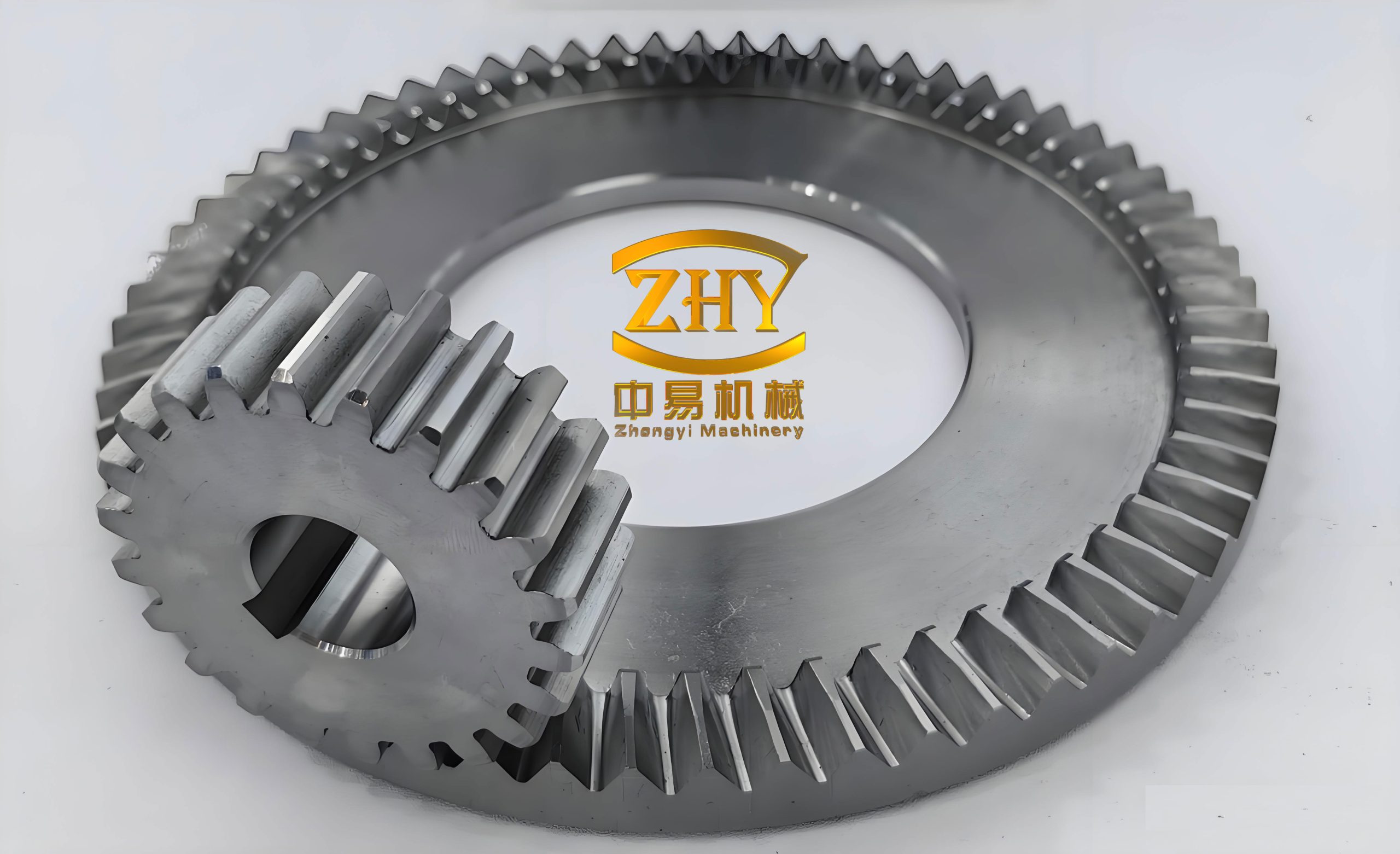
I begin from the meshing principle of conjugate surfaces. The shaper cutter is the generating tool, and the face gear is the generated member. I build a set of rigid coordinate systems, derive the family of shaper cutter surfaces in the face gear coordinate system, impose the meshing equation, and obtain the working tooth surface of the face gear. I then derive the transition surface from the shaper cutter tip cylinder. From the same equations, I extract the undercutting limit and the tooth-tip pointing limit. These limits give the minimum inner radius and the maximum outer radius of the face gear in closed form. I use those radii to choose the face gear tooth width, and I verify that the dimensionless width coefficient is large enough for high-power face gear applications.
For the pinion, I derive both the involute working surface and the true transition surface produced by shaper cutting. I do not approximate the root fillet with a circular arc. Instead, I compute the long-axis epicycloid-like surface that is actually generated by the tip of the shaper cutter. This is important because a face gear drive is sensitive to pinion root geometry, especially when the pinion is the driving member and must transmit torque smoothly. After deriving the equations, I implement them in MATLAB, generate point clouds for the left and right working surfaces and transition surfaces, import the point clouds into UG, and build exact three-dimensional solid models. I then assemble the offset non-orthogonal face gear and the pinion with standard clearance and zero backlash, and I perform kinematic simulation. The simulation shows no interference and confirms the designed angular velocity ratio. In this way, I validate both the analytical derivation and the numerical modeling procedure.
The design problem is governed by several independent parameters. The most important are the module, the shaper cutter tooth number, the pinion tooth number, the face gear tooth number, the pressure angle, the shaper cutter addendum coefficient, the pinion addendum coefficient, the face gear addendum coefficient, the offset distance, and the shaft angle. I collect these parameters in a design table so that the derivation can be followed without ambiguity. The coordinate systems are equally important, because every transformation matrix must be written in the correct order. I define the shaper cutter coordinate system, the face gear coordinate system, the machine frame coordinate system, the auxiliary coordinate system, and the reference coordinate system used for modeling. The transformation from the shaper cutter to the face gear is a product of three matrices: one from the shaper cutter to the auxiliary frame, one from the auxiliary frame to the machine frame, and one from the machine frame to the face gear. I write this product explicitly and use it throughout the derivation.
| Coordinate system | Role in the derivation |
|---|---|
| $$S_s(x_s,y_s,z_s)$$ | Rigidly attached to the shaper cutter; carries the involute cutter surface and its unit normal. |
| $$S_2(x_2,y_2,z_2)$$ | Rigidly attached to the face gear; receives the family of cutter surfaces and the meshing equation. |
| $$S_m(x_m,y_m,z_m)$$ | Rigidly attached to the machine frame; represents the relative motion of the generating process. |
| $$S_p(x_p,y_p,z_p)$$ | Auxiliary frame rigidly connected to the machine frame; simplifies the matrix product. |
| $$S_c(x_c,y_c,z_c)$$ | Reference frame for point-cloud modeling; obtained by rotating and translating the face gear frame. |
The shaper cutter surface is an involute surface. I choose the symmetry axis of the shaper cutter tooth space as one coordinate axis, so the involute equations take a compact form. The position vector of a point on the shaper cutter surface is written as a function of two surface parameters: one along the tooth width and one along the tooth height. The upper and lower signs correspond to the left and right sides of the shaper cutter tooth space.
$$ \mathbf{r}_s(u_s,\theta_s)= \begin{bmatrix} \pm r_{bs}\left[\sin(\theta_{os}+\theta_s)-\theta_s\cos(\theta_{os}+\theta_s)\right] \\ -r_{bs}\left[\cos(\theta_{os}+\theta_s)+\theta_s\sin(\theta_{os}+\theta_s)\right] \\ u_s \\ 1 \end{bmatrix} $$
Here, $$r_{bs}$$ is the base radius of the shaper cutter, $$u_s$$ is the tooth-width parameter, $$\theta_s$$ is the tooth-height parameter, and $$\theta_{os}$$ determines the tooth-space width on the base circle. The pressure angle is denoted by $$\alpha$$, and the involute function is denoted by $$\operatorname{inv}\alpha$$. The relationship is
$$ \theta_{os}=\frac{\pi}{2N_s}-\operatorname{inv}\alpha $$
where $$N_s$$ is the number of teeth of the shaper cutter. The unit normal to the shaper cutter surface is obtained from the cross product of the two partial derivatives. I normalize the cross product and obtain
$$ \mathbf{n}_s= \frac{\frac{\partial \mathbf{r}_s}{\partial \theta_s}\times \frac{\partial \mathbf{r}_s}{\partial u_s}} {\left\|\frac{\partial \mathbf{r}_s}{\partial \theta_s}\times \frac{\partial \mathbf{r}_s}{\partial u_s}\right\|} = \begin{bmatrix} -\cos(\theta_{os}+\theta_s) \\ \mp \sin(\theta_{os}+\theta_s) \\ 0 \end{bmatrix} $$
The surface family of the shaper cutter in the face gear coordinate system is obtained by applying the transformation matrix from the shaper cutter frame to the face gear frame. I write the transformation as
$$ \mathbf{r}_2(u_s,\theta_s,\phi_s)=M_{2s}(\phi_s)\mathbf{r}_s(u_s,\theta_s) $$
The matrix $$M_{2s}$$ is the product of three elementary transformations. I expand it explicitly because every later equation depends on its entries:
$$ M_{2s}(\phi_s)=M_{2p}M_{pm}M_{ms}= \begin{bmatrix} M_{11} & M_{12} & -\sin\phi_2\sin\gamma_m & -e\cos\phi_2 \\ M_{21} & M_{22} & -\cos\phi_2\sin\gamma_m & e\sin\phi_2 \\ M_{31} & M_{32} & \cos\gamma_m & 0 \\ 0 & 0 & 0 & 1 \end{bmatrix} $$
The entries of the upper-left block are
$$ M_{11}=\cos\phi_2\cos\phi_s+\sin\phi_2\cos\gamma_m\sin\phi_s $$
$$ M_{12}=-\cos\phi_2\sin\phi_s+\sin\phi_2\cos\gamma_m\cos\phi_s $$
$$ M_{21}=-\sin\phi_2\cos\phi_s+\cos\phi_2\cos\gamma_m\sin\phi_s $$
$$ M_{22}=\sin\phi_2\sin\phi_s+\cos\phi_2\cos\gamma_m\cos\phi_s $$
$$ M_{31}=\sin\gamma_m\sin\phi_s $$
$$ M_{32}=\sin\gamma_m\cos\phi_s $$
The angles $$\phi_s$$ and $$\phi_2$$ are the rotation angles of the shaper cutter and the face gear, respectively. They are related by the tooth-number ratio:
$$ \phi_2=\phi_s\frac{N_s}{N_2} $$
where $$N_2$$ is the number of teeth of the face gear. The offset distance is $$e$$, and the shaft angle is $$\gamma_m$$. The sign conventions are chosen so that the same equations describe shaft angles greater than ninety degrees and shaft angles less than ninety degrees. The only difference is the range of the angular parameters and the orientation of the asymmetric working surfaces.
The meshing equation is the condition that the relative velocity between the shaper cutter surface and the face gear surface is perpendicular to the common normal. I write it as
$$ f(u_s,\theta_s,\phi_s)=\mathbf{n}_s\cdot \mathbf{V}_s^{(s2)}=0 $$
The relative velocity $$\mathbf{V}_s^{(s2)}$$ is the difference between the velocity of a point on the shaper cutter surface and the velocity of the same point regarded as a point on the face gear surface. Expressing both velocities in the shaper cutter frame and substituting the shaper cutter surface equations gives the explicit meshing equation:
$$ f(u_s,\theta_s,\phi_s)= r_{bs}(1-m_{2s}\cos\gamma_m) -u_s m_{2s}\sin\gamma_m\cos(\phi_s\pm\theta_s\pm\theta_{os}) \mp e m_{2s}\cos\gamma_m\sin(\phi_s\pm\theta_s\pm\theta_{os})=0 $$
The ratio $$m_{2s}$$ is the face gear to shaper cutter tooth ratio:
$$ m_{2s}=\frac{N_s}{N_2} $$
The meshing equation is linear in the tooth-width parameter $$u_s$$. Therefore, I solve it directly and obtain
$$ u_s= \frac{r_{bs}(1-m_{2s}\cos\gamma_m)\mp h_s} {m_{2s}\sin\gamma_m\cos(\phi_s\pm\theta_s\pm\theta_{os})} $$
where
$$ h_s=e m_{2s}\cos\gamma_m\sin(\phi_s\pm\theta_s\pm\theta_{os}) $$
I then substitute this result into the shaper cutter surface and apply the transformation matrix. The working tooth surface of the offset non-orthogonal face gear in the face gear coordinate system is
$$ \mathbf{r}_2(\theta_s,\phi_s)= \begin{bmatrix} M_{11}x_s+M_{12}y_s-z_s\sin\phi_2\sin\gamma_m-e\cos\phi_2 \\ M_{21}x_s+M_{22}y_s-z_s\cos\phi_2\sin\gamma_m+e\sin\phi_2 \\ M_{31}x_s+M_{32}y_s-z_s\cos\gamma_m \\ 1 \end{bmatrix} $$
This expression is one of the central results of my derivation. It describes both the left and the right working surfaces, because the upper and lower signs in the shaper cutter equations and in the meshing equation select the two sides. The surfaces are not mirror images when the shaft angle is not ninety degrees and the offset is nonzero. That asymmetry is the source of the special contact behavior of the offset non-orthogonal face gear.
For modeling, I transform the working surface into the reference coordinate system $$S_c$$. I first rotate the face gear coordinate system about its own axis by the shaft angle, and then I translate it along the face gear axis. The transformation matrix is
$$ M_{c2}= \begin{bmatrix} 1 & 0 & 0 & 0 \\ 0 & \cos\gamma_m & \sin\gamma_m & h \\ 0 & -\sin\gamma_m & \cos\gamma_m & h\cot\gamma_m \\ 0 & 0 & 0 & 1 \end{bmatrix} $$
The distance $$h$$ depends on the module, the shaper cutter tooth number, and the face gear addendum coefficient:
$$ h=\frac{mN_s}{2}-mh_a^* $$
where $$m$$ is the module and $$h_a^*$$ is the face gear addendum coefficient. In the reference system, the working surface is
$$ \mathbf{r}_c(\theta_s,\phi_s)=M_{c2}\mathbf{r}_2(\theta_s,\phi_s) $$
The transition surface of the face gear is generated by the tip cylinder of the shaper cutter. The tip cylinder intersects the involute working surface along a line. That line is the boundary between the working surface and the transition surface. I denote the maximum tooth-height parameter of the shaper cutter by $$\theta_s^*$$. It is determined by the shaper cutter tip radius and the base radius:
$$ \theta_s^*=\frac{\sqrt{r_{as}^2-r_{bs}^2}}{r_{bs}} $$
where
$$ r_{as}=\frac{mN_s}{2}+h_{as}^*m $$
and $$h_{as}^*$$ is the shaper cutter addendum coefficient. The tip line of the shaper cutter in its own frame is
$$ \mathbf{r}_s^*(u_s)=\mathbf{r}_s(u_s,\theta_s^*) $$
The transition surface in the face gear frame is obtained by applying the same family transformation:
$$ \mathbf{r}_2^*(u_s,\phi_s)=M_{2s}(\phi_s)\mathbf{r}_s^*(u_s) $$
In the reference frame, the transition surface is
$$ \mathbf{r}_c^*(u_s,\phi_s)=M_{c2}\mathbf{r}_2^*(u_s,\phi_s) $$
The common tangent line between the working surface and the transition surface is also generated by the shaper cutter tip. It is obtained by setting $$\theta_s=\theta_s^*$$ in the working surface equations and then applying the meshing equation. In the face gear frame, the tangent line is
$$ \mathbf{r}_2^{L*}(\phi_s)=M_{2s}(\phi_s)\mathbf{r}_s^{L*}(\phi_s) $$
and in the reference frame it is
$$ \mathbf{r}_c^{L*}(\phi_s)=M_{c2}\mathbf{r}_2^{L*}(\phi_s) $$
This line is important in the point-cloud modeling procedure. It allows me to join the working surface and the transition surface without gaps or overlaps. If the line is computed correctly, the resulting solid model is smooth and the transition surface blends exactly into the working surface.
Undercutting is the first geometric limit that I must avoid. In the generating process, undercutting occurs when the shaper cutter surface contains a limit line that maps to a singular point on the face gear tooth surface. I determine this limit line by combining the shaper cutter surface equations, the meshing equation, and the condition that the Jacobian of the mapping vanishes. The limit line is the solution of
$$ \mathbf{r}_s=\mathbf{r}_s(u_s,\theta_s),\quad f(u_s,\theta_s,\phi_s)=0,\quad \Delta_2=0 $$
The Jacobian determinant is
$$ \Delta_2= \begin{vmatrix} \frac{\partial f}{\partial u_s} & \frac{\partial f}{\partial \theta_s} & \frac{\partial f}{\partial \phi_s}\dot{\phi}_s \\ \frac{\partial x_s}{\partial u_s} & \frac{\partial x_s}{\partial \theta_s} & \omega_s^{(s)}V_{sx}^{(s2)} \\ \frac{\partial z_s}{\partial u_s} & \frac{\partial z_s}{\partial \theta_s} & \omega_s^{(s)}V_{sz}^{(s2)} \end{vmatrix}=0 $$
I solve this system together with the shaper cutter tip condition $$\theta_s=\theta_s^*$$. The solution gives the limiting point on the shaper cutter tip. I transform that point to the face gear frame and then to the reference frame. If the coordinates of the limiting point in the reference frame are $$(x_{kc},y_{kc},z_{kc})$$, the minimum inner radius of the face gear is
$$ R_1=\sqrt{x_{kc}^2+z_{kc}^2} $$
Because the left and right tooth surfaces are asymmetric, two different limiting points may appear. I compute one for the left surface and one for the right surface. I denote them by $$R_1^L$$ and $$R_1^R$$. The actual minimum inner radius that avoids undercutting on both sides is the larger of the two:
$$ R_1=\max\left(R_1^L,R_1^R\right) $$
I always choose the inner radius of the face gear to be slightly larger than this analytical minimum. That provides a small safety margin without sacrificing useful tooth width.
Tooth-tip pointing is the second geometric limit. Pointing occurs when the two sides of the face gear tooth meet at the top and the tooth thickness becomes zero. Because the surfaces are asymmetric, the pointing condition must be written separately for the left and right sides. In the reference frame, the condition is
$$ x_c^L(\theta_s^L,\phi_s^L)=x_c^R(\theta_s^R,\phi_s^R) $$
$$ z_c^L(\theta_s^L,\phi_s^L)=z_c^R(\theta_s^R,\phi_s^R) $$
$$ y_c^L(\theta_s^L,\phi_s^L)=0 $$
$$ y_c^R(\theta_s^R,\phi_s^R)=0 $$
I solve this nonlinear system numerically. The solution gives the critical points on the left and right surfaces at which the tooth thickness vanishes. Their coordinates in the reference frame are $$(x_{Lc},y_{Lc},z_{Lc})$$ and $$(x_{Rc},y_{Rc},z_{Rc})$$. The maximum outer radius that avoids pointing is
$$ R_2=\sqrt{x_{Lc}^2+z_{Lc}^2}=\sqrt{x_{Rc}^2+z_{Rc}^2} $$
In practice, I choose the outer radius of the face gear to be slightly smaller than this value. The difference between the minimum inner radius and the maximum outer radius gives the available tooth width:
$$ B=R_2-R_1 $$
For high-power face gear drives, the dimensionless tooth-width coefficient should satisfy
$$ c=\frac{B}{m}=\frac{R_2-R_1}{m}\ge 10 $$
This criterion is not merely a rule of thumb. It reflects the bending stress requirement in the face gear tooth. If the coefficient is too small, the tooth is too narrow for the transmitted load, and bending stress becomes excessive. If the coefficient is too large, the outer radius may exceed the pointing limit or the inner radius may enter the undercut region. Therefore, the design must balance the two limits. If the computed coefficient is less than ten, I can increase the tooth numbers, increase the shaft angle, or reduce the offset distance. Each of these changes alters the position of the undercut limit and the pointing limit, and the analytical formulas allow me to reevaluate the design quickly.
| Quantity | Meaning | Design rule |
|---|---|---|
| $$R_1$$ | Minimum inner radius of the face gear | Larger than or equal to the undercut limit. |
| $$R_2$$ | Maximum outer radius of the face gear | Smaller than or equal to the pointing limit. |
| $$B$$ | Face gear tooth width | $$B=R_2-R_1$$. |
| $$c$$ | Dimensionless tooth-width coefficient | $$c=B/m\ge 10$$ for high-power face gear drives. |
| $$\gamma_m$$ | Shaft angle between the face gear axis and the shaper cutter axis | May be greater or less than ninety degrees. |
| $$e$$ | Offset distance between the two axes | Controls asymmetry and contact pattern. |
I now apply the derivation to a specific face gear drive. I choose a module of three millimeters, a shaper cutter with twenty-five teeth, a pinion with twenty-two teeth, a face gear with one hundred fifteen teeth, and a pressure angle of twenty degrees. The shaper cutter addendum coefficient is one and twenty-five hundredths, while the pinion and face gear addendum coefficients are one. The offset distance is twenty millimeters, and the shaft angle is one hundred five degrees. With these parameters, the undercut limit gives a minimum inner radius of approximately one hundred seventy-six decimal zero two millimeters, and the pointing limit gives a maximum outer radius of approximately two hundred six decimal zero five millimeters. I select an inner radius slightly larger than the undercut limit and an outer radius slightly smaller than the pointing limit. The resulting tooth width is sufficient to satisfy the bending stress criterion.
| Parameter | Value |
|---|---|
| Module $$m$$ | 3 mm |
| Shaper cutter tooth number $$N_s$$ | 25 |
| Pinion tooth number $$N_1$$ | 22 |
| Pressure angle $$\alpha$$ | 20 degrees |
| Face gear tooth number $$N_2$$ | 115 |
| Shaper cutter addendum coefficient $$h_{as}^*$$ | 1.25 |
| Pinion addendum coefficient $$h_{a1}^*$$ | 1 |
| Face gear addendum coefficient $$h_a^*$$ | 1 |
| Offset distance $$e$$ | 20 mm |
| Shaft angle $$\gamma_m$$ | 105 degrees |
| Face gear inner radius $$R_1$$ | 176.02 mm |
| Face gear outer radius $$R_2$$ | 206.05 mm |
When the shaft angle is changed to seventy-five degrees, the same equations still apply. The only difference is that the shaft angle is less than ninety degrees, and the orientation of the asymmetric surfaces changes. For the same module, tooth numbers, pressure angle, addendum coefficients, and offset distance, the undercut limit and the pointing limit shift. The minimum inner radius becomes approximately one hundred seventy-two decimal seven millimeters, and the maximum outer radius becomes approximately two hundred three decimal seven millimeters. I use these values to build a second face gear model. The fact that the same derivation covers both cases is a strong indication that the formulation is general and not restricted to a particular shaft-angle range.
The mating pinion is an involute spur gear. I derive its working surface and its transition surface separately. The working surface is the standard involute helicoid reduced to the spur case. I choose the symmetry axis of the pinion tooth space as one coordinate axis, so the involute equations are compact. The position vector of a point on the pinion working surface is
$$ \mathbf{r}_1(u_1,\theta_1)= \begin{bmatrix} \pm r_{b1}\left(\sin\Xi-\theta_1\cos\Xi\right) \\ r_{b1}\left(\cos\Xi+\theta_1\sin\Xi\right) \\ u_1 \\ 1 \end{bmatrix} $$
where
$$ \Xi=\theta_{c1}+\theta_1-\phi_{c1} $$
Here, $$r_{b1}$$ is the pinion base radius, $$u_1$$ is the tooth-width parameter, $$\theta_1$$ is the tooth-height parameter, $$\theta_{c1}$$ is half the tooth-space angle on the pitch circle, and $$\phi_{c1}$$ is half the angular pitch:
$$ \phi_{c1}=\frac{\pi}{N_1} $$
The transition surface of the pinion is not a simple circular fillet. It is generated by the tip cylinder of the shaper cutter during pinion cutting. I model the shaper cutter as a gear that rolls on the pinion pitch circle. The tip line of the shaper cutter sweeps a long-axis epicycloid-like surface. The position vector of the pinion transition surface is
$$ \mathbf{r}_1^*(u_1,\phi_1)= \begin{bmatrix} -(r_{p1}+r_{ps})\sin\psi_1+r_{as}\cos\psi_s \\ (r_{p1}+r_{ps})\cos\psi_1-r_{as}\sin\psi_s \\ u_1 \\ 1 \end{bmatrix} $$
The angle $$\psi_1$$ is the pinion tooth-width parameter, and $$\psi_s$$ is the corresponding shaper cutter parameter:
$$ \psi_1=\phi_{c1}-\phi_1 $$
$$ \psi_s=\frac{\pi}{2}-\psi_1-(\Xi_s-\phi_s) $$
The angle $$\Xi_s$$ is the angle between the shaper cutter tip line and its tooth-space symmetry plane:
$$ \Xi_s=\frac{\pi}{N_s}-\theta_{os}-\theta_s^*+\arctan\theta_s^* $$
The pitch radii of the pinion and the shaper cutter are denoted by $$r_{p1}$$ and $$r_{ps}$$. The rotation angles are related by
$$ \phi_1=\phi_s\frac{N_s}{N_1} $$
These equations are sufficient to generate the true pinion root fillet. I do not replace the fillet with an arc, and I do not use a simplified trochoid. This matters for the offset non-orthogonal face gear drive because the pinion root stress concentration is sensitive to the exact transition geometry. By computing the true transition surface, I can evaluate root stress and, if necessary, apply a controlled modification to the fillet without losing the conjugate working surface.
Once the analytical equations are complete, I use the point-cloud method to build the solid models. The point-cloud method is more accurate than the section-lofting method for this class of face gear. It is also easier to control because the density of the point cloud can be increased until the surface deviation is below the required tolerance. I implement the following procedure for the face gear working surface. First, I input the module, shaper cutter tooth number, pressure angle, face gear tooth number, shaper cutter addendum coefficient, face gear addendum coefficient, offset distance, and shaft angle. I then compute the base radius, the tooth ratio, the involute function, the base-circle tooth-space angle, the reference-system offset, the maximum tooth-height parameter, and the shaper cutter tip radius. Next, I compute the undercut limit and the pointing limit, and I choose the inner radius, the outer radius, and the tooth width. I discretize the tooth width into a number of slices. For each slice, I solve the nonlinear system that places the point at the correct radius and on the symmetry plane. This gives the angular parameters for that slice. I then discretize the tooth-height parameter between the inner boundary and the tip boundary, and for each value I solve for the corresponding angular parameter. Substituting the parameter pairs into the working-surface equation gives a grid of points on the left and right surfaces. The same process is repeated for the transition surface, except that the tooth-height parameter is fixed at the shaper cutter tip value and the variable is the tooth-width parameter. The common tangent line is computed from the working-surface parameters at the tip boundary. The result is a complete point cloud for one face gear tooth.
| Step | Operation | Output |
|---|---|---|
| 1 | Input basic design parameters. | $$m,N_s,N_1,N_2,\alpha,h_{as}^*,h_{a1}^*,h_a^*,e,\gamma_m$$ |
| 2 | Compute derived quantities. | $$r_{bs},m_{2s},\operatorname{inv}\alpha,\theta_{os},h,\theta_s^*,r_{as}$$ |
| 3 | Solve undercut and pointing limits. | $$R_1,R_2,B,c$$ |
| 4 | Discretize tooth width. | $$B_j,\quad j=1,\dots,J$$ |
| 5 | Solve for angular parameters on each slice. | $$\phi_{sj},\theta_{sj}$$ |
| 6 | Discretize tooth height. | $$\theta_{sji},\quad i=1,\dots,I$$ |
| 7 | Solve for remaining parameter. | $$\phi_{sj}’$$ |
| 8 | Evaluate working-surface equation. | Point cloud on left and right working surfaces. |
| 9 | Repeat for transition surface and tangent line. | Point cloud on transition surfaces and common tangent. |
I write the MATLAB program so that the left and right sides are computed separately. Because the face gear is asymmetric, I cannot use a mirror operation. I must solve the nonlinear equations twice, once for each side. This doubles the computational effort, but it guarantees that the asymmetry is preserved exactly. The point cloud is written to a data file in a format that can be imported into UG. I use a structured grid so that the points can be connected into surface patches without ambiguity. The density of the grid is controlled by the number of slices and the number of points along the tooth height. In my numerical experiments, fifteen slices and fifteen points along the tooth height are sufficient to produce a smooth model for visualization. For a manufacturing-grade model, I increase the density until the chordal deviation is below the specified tolerance.
The transition surface is generated in a similar way. The variables are the tooth-width parameter and the angular parameter. I first solve for the minimum and maximum angular values that keep the transition surface within the selected tooth width. I then discretize the angular interval and solve for the tooth-width parameter on each slice. The resulting point cloud is joined to the working surface along the common tangent line. I compute that line from the working-surface solution at the tip boundary, so the two surface patches share exactly the same boundary points. This eliminates gaps and overlaps in the solid model.
After generating the point clouds, I import them into UG. I create a sketch of the face gear blank in the reference coordinate system, revolve it to form the blank, and then use the point clouds to construct the left working surface, the right working surface, the left transition surface, the right transition surface, and the common tangent lines. I use surface construction tools to fit smooth surfaces through the point clouds. I then trim the blank with the surfaces and pattern the single tooth around the face gear axis. The result is an exact three-dimensional solid model of the offset non-orthogonal face gear. I repeat the process for a shaft angle greater than ninety degrees and for a shaft angle less than ninety degrees. Both models are free of undercutting and pointing, and both show the characteristic asymmetric tooth form.
The pinion is modeled in the same way. I compute the point cloud for the involute working surface and the true transition surface. I import the point cloud into UG, create the pinion blank, and construct the solid model. The pinion tooth is symmetric about its mid-plane, so I can mirror the left and right surfaces after computing one side. The transition surface is generated from the shaper cutter tip line, so it matches the actual cutting process. The resulting pinion model has the correct involute profile, the correct root fillet, and the correct tooth width. I use the same module, pressure angle, and addendum coefficients as the face gear.
| Component | Working surface source | Transition surface source | Symmetry |
|---|---|---|---|
| Offset non-orthogonal face gear | Envelope of shaper cutter involute surface | Envelope of shaper cutter tip cylinder | Asymmetric left and right sides |
| Involute spur pinion | Involute surface equation | Long-axis epicycloid-like surface from shaper cutter tip | Symmetric about tooth mid-plane |
I assemble the face gear and the pinion in UG with the designed offset distance and shaft angle. I set the pinion tooth width to thirty millimeters. The assembly has no backlash, and the clearance is the standard value of zero point two five times the module, which is zero point seven five millimeters. The assembly succeeds without interference or forced fitting. This is a direct check on the accuracy of the tooth-surface equations. If the working surfaces or the transition surfaces were even slightly inconsistent, the assembly would either jam or leave an unacceptable backlash. The fact that the standard clearance is obtained exactly confirms that the analytical derivation and the point-cloud modeling are consistent.
I then perform kinematic simulation. I add links, revolute joints, and a gear coupling. I use the pinion as the driving member. I apply a constant angular velocity to the pinion and solve the motion for five seconds with one hundred fifty steps. I use the interference-checking function of the kinematic simulation module. I select the pinion as the first group and the face gear as the second group, set the mode to precise solids, set the clearance to zero, and request high-light display for interference. During the entire simulation, no interference is detected. Neither the pinion nor the face gear is highlighted. This means that the conjugate surfaces remain in proper contact and that the transition surfaces do not collide with the mating tooth surfaces.
I also record the angular velocities of the pinion and the face gear. The pinion is driven at thirty-five degrees per second. The face gear rotates about its own axis. The angular velocity ratio should be equal to the tooth-number ratio. The tooth-number ratio is
$$ i_{12}=\frac{N_2}{N_1}=\frac{115}{22}\approx 5.227 $$
The simulation shows that the pinion angular velocity and the face gear angular velocity are both constant after the initial transient. The ratio of the two angular velocities matches the designed transmission ratio. This is a second independent confirmation of the design. It shows that the meshing equation, the surface generation, and the solid modeling all preserve the conjugate relationship.
| Simulation quantity | Value or result |
|---|---|
| Driving member | Involute spur pinion |
| Driven member | Offset non-orthogonal face gear |
| Pinion driving angular velocity | 35 degrees per second |
| Simulation time | 5 seconds |
| Simulation steps | 150 |
| Interference check mode | Precise solids, zero clearance |
| Interference result | No interference detected |
| Angular velocity ratio | Matches $$N_2/N_1=115/22$$ |
| Standard clearance | 0.25 m = 0.75 mm |
| Backlash | Zero |
The results confirm several important points. First, the offset non-orthogonal face gear can be designed exactly by treating it as the envelope of a shaper cutter surface. Second, the undercut limit and the pointing limit can be expressed in closed form, and the resulting minimum inner radius and maximum outer radius are reliable. Third, the point-cloud method is capable of producing solid models that are accurate enough for assembly and kinematic simulation. Fourth, the true pinion transition surface, which is generated by the shaper cutter tip, is necessary for a complete and interference-free model. Fifth, the asymmetry of the face gear tooth surfaces is not a defect; it is a geometric feature that must be preserved and can be used to improve the transmission.
The design procedure that I have described is general. It does not depend on a particular shaft angle or a particular offset distance. It can be applied to face gear drives with shaft angles greater than ninety degrees, less than ninety degrees, or equal to ninety degrees. When the offset distance is set to zero, the equations reduce to the non-orthogonal face gear case. When the shaft angle is set to ninety degrees and the offset is set to zero, the equations reduce further to the orthogonal face gear case. This means that the same framework can be used to design a wide range of face gear transmissions without changing the basic derivation. The only changes are the numerical values of the parameters and the ranges of the angular variables.
The point-cloud method has another advantage. It allows me to control the accuracy of the model directly. The surface deviation decreases as the number of points increases. I can therefore generate a coarse model for rapid visualization and a fine model for manufacturing. I can also export the point cloud to a computer-aided manufacturing system and use it to generate tool paths for cutting or grinding. This is important because the offset non-orthogonal face gear is difficult to machine by conventional methods. A precise point-cloud model provides the geometric information needed for both validation and production.
In my numerical implementation, I paid particular attention to the nonlinear equations for the undercut limit and the pointing limit. The undercut limit requires the solution of a three-by-three determinant equation together with the meshing equation and the shaper cutter tip condition. The pointing limit requires the solution of a system of four equations for four unknowns. Both systems are nonlinear, and both require good initial guesses. I obtained those initial guesses from the geometry of the orthogonal face gear and then continued the solution as the offset distance and shaft angle were varied. This continuation approach is robust and avoids convergence to spurious roots. Once the limits are found, the radii are computed by a simple square root. The entire design can therefore be automated.
I also examined the effect of the offset distance on the tooth width. As the offset distance increases, the asymmetry of the face gear tooth becomes more pronounced. The undercut limit and the pointing limit move, and the available tooth width changes. In some cases, the offset distance can be used to increase the contact ratio without increasing the outer radius. In other cases, the offset distance must be reduced to maintain the dimensionless tooth-width coefficient above ten. The analytical formulas allow me to explore these trade-offs quickly. I can generate a family of designs and select the one that best meets the requirements for load capacity, compactness, and contact pattern.
The shaft angle has a similar effect. When the shaft angle is close to ninety degrees, the face gear tooth is nearly symmetric, and the design is similar to that of an orthogonal face gear. When the shaft angle deviates from ninety degrees, the tooth becomes asymmetric, and the contact pattern changes. The offset distance and the shaft angle together determine the shape of the working surface and the position of the transition surface. By deriving the equations without assuming orthogonality, I can handle all of these cases in a single framework. This is more efficient than deriving separate equations for each configuration.
The pinion transition surface is generated by the shaper cutter tip, and its shape depends on the shaper cutter addendum coefficient. If the addendum coefficient is increased, the tip line moves outward, and the transition surface becomes larger. If the addendum coefficient is decreased, the transition surface becomes smaller. In a face gear drive, the pinion root fillet must not interfere with the face gear tooth tip. Therefore, the shaper cutter addendum coefficient and the face gear addendum coefficient must be chosen together. I use the standard clearance to set the relationship between the two. The clearance is the difference between the face gear addendum and the pinion dedendum, and it must be positive. In my design, the clearance is zero point seven five millimeters, which is the standard value for the module. The simulation confirms that this clearance is maintained throughout the mesh cycle.
The face gear transition surface is generated by the shaper cutter tip cylinder. Its shape is determined by the shaper cutter tip radius and the generating motion. The transition surface must blend smoothly into the working surface along the common tangent line. If the tangent line is not computed correctly, a sharp edge or a gap appears at the root of the face gear tooth. Such a defect would cause stress concentration and could lead to premature failure. By computing the common tangent line from the working-surface solution, I ensure that the transition surface is tangent to the working surface. The resulting face gear tooth has a smooth root fillet that is consistent with the generating process.
The point-cloud model can be used to compute the actual contact pattern. Although I did not perform a full loaded tooth contact analysis in this work, the kinematic simulation provides a first check. A more detailed analysis would require the application of a load and the solution of the contact equations. The point-cloud model can be used as the input for such an analysis. The same model can be used for finite element analysis. By exporting the solid model to a finite element program, I can compute the bending stress and the contact stress in the face gear and the pinion. This is a natural extension of the design procedure. The analytical radii and the point-cloud model together provide the geometric basis for stress analysis and optimization.
The design method also provides a way to evaluate the effect of manufacturing errors. If the shaft angle or the offset distance is slightly different from the design value, the contact pattern shifts. The point-cloud model can be modified to include these errors, and the kinematic simulation can be repeated. This allows me to determine the sensitivity of the design to installation errors. In a helicopter transmission, for example, the shaft angle and the offset distance may vary due to elastic deformation of the housing. A robust design must maintain a favorable contact pattern even when these errors are present. The analytical formulation makes it possible to study these effects without rebuilding the entire model from scratch.
In summary, I have developed a complete and accurate design method for offset non-orthogonal face gear drives. I derived the working tooth surface and the transition surface of the face gear from the shaper cutter envelope. I derived the undercut limit and the pointing limit and obtained analytical formulas for the minimum inner radius and the maximum outer radius. I derived the working surface and the true transition surface of the involute spur pinion. I implemented the equations in MATLAB and generated point clouds for both members. I imported the point clouds into UG and built exact three-dimensional solid models. I assembled the drive with standard clearance and zero backlash. I performed kinematic simulation and confirmed that there is no interference and that the angular velocity ratio matches the design. The method is general, accurate, and suitable for the design of face gear transmissions with various shaft angles, offset distances, and tooth numbers.
The most important equations are collected here for reference. The shaper cutter surface is
$$ \mathbf{r}_s(u_s,\theta_s)= \begin{bmatrix} \pm r_{bs}\left[\sin(\theta_{os}+\theta_s)-\theta_s\cos(\theta_{os}+\theta_s)\right] \\ -r_{bs}\left[\cos(\theta_{os}+\theta_s)+\theta_s\sin(\theta_{os}+\theta_s)\right] \\ u_s \\ 1 \end{bmatrix} $$
The meshing equation is
$$ f(u_s,\theta_s,\phi_s)= r_{bs}(1-m_{2s}\cos\gamma_m) -u_s m_{2s}\sin\gamma_m\cos(\phi_s\pm\theta_s\pm\theta_{os}) \mp e m_{2s}\cos\gamma_m\sin(\phi_s\pm\theta_s\pm\theta_{os})=0 $$
The face gear working surface is
$$ \mathbf{r}_2(\theta_s,\phi_s)= \begin{bmatrix} M_{11}x_s+M_{12}y_s-z_s\sin\phi_2\sin\gamma_m-e\cos\phi_2 \\ M_{21}x_s+M_{22}y_s-z_s\cos\phi_2\sin\gamma_m+e\sin\phi_2 \\ M_{31}x_s+M_{32}y_s-z_s\cos\gamma_m \\ 1 \end{bmatrix} $$
The minimum inner radius that avoids undercutting is
$$ R_1=\max\left(R_1^L,R_1^R\right) $$
The maximum outer radius that avoids pointing is
$$ R_2=\sqrt{x_{Lc}^2+z_{Lc}^2}=\sqrt{x_{Rc}^2+z_{Rc}^2} $$
The tooth-width criterion is
$$ c=\frac{R_2-R_1}{m}\ge 10 $$
The pinion working surface is
$$ \mathbf{r}_1(u_1,\theta_1)= \begin{bmatrix} \pm r_{b1}\left(\sin\Xi-\theta_1\cos\Xi\right) \\ r_{b1}\left(\cos\Xi+\theta_1\sin\Xi\right) \\ u_1 \\ 1 \end{bmatrix} $$
The pinion transition surface is
$$ \mathbf{r}_1^*(u_1,\phi_1)= \begin{bmatrix} -(r_{p1}+r_{ps})\sin\psi_1+r_{as}\cos\psi_s \\ (r_{p1}+r_{ps})\cos\psi_1-r_{as}\sin\psi_s \\ u_1 \\ 1 \end{bmatrix} $$
These equations, together with the point-cloud procedure and the kinematic simulation, form a complete design and validation workflow. I can apply the same workflow to other face gear configurations by changing the input parameters and recomputing the point clouds. The result is a precise, manufacturable, and verifiable face gear drive.