
I present a precise design method for skiving tools used to manufacture orthogonal spur face gears. My starting point is the crossed-axis meshing behavior between a skiving tool and face gears. I analyze the skiving process as a pair of conjugated gear motions, I derive the tooth surface of the skiving tool by enveloping the involute tooth profile of a cylindrical pinion that meshes with face gears, and I obtain the cutting edge from a normal section that includes a controlled rake angle. I then solve the meshing conditions between the cutting edge and face gears, derive the numerical control motion law, build a theoretical tooth surface model, perform simulation machining, and compare the simulated tooth surface with the theoretical tooth surface of face gears. When the tool has no manufacturing error, my method reproduces the theoretical tooth surface of face gears. In the virtual machining environment, the tooth surface error remains within ten micrometers. This result supports the use of my design method for high-accuracy skiving of face gears.
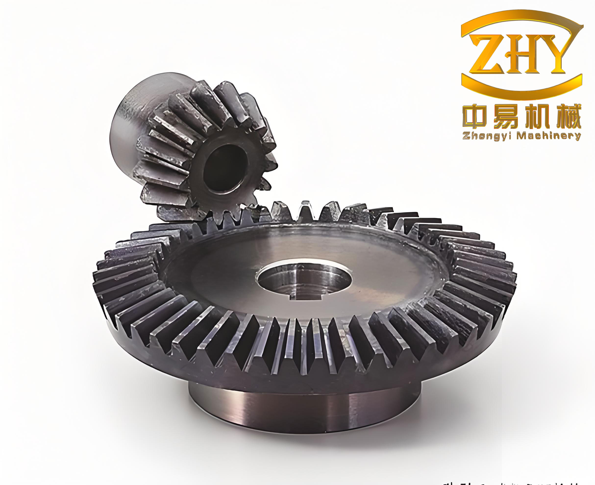
The central idea is that face gears should not be treated as an isolated geometry problem. Instead, I treat the skiving tool as an enveloping body generated by the same pinion that is conjugate to face gears. This choice removes the principle error that usually appears when a conventional cylindrical skiving tool is used directly on face gears. The skiving tool cutting edge lies on the theoretical tool tooth surface, so the edge itself carries the correct generating information. When this edge is moved relative to face gears according to the correct crossed-axis motion, the resulting envelope belongs to the theoretical tooth surface of face gears. I will describe this chain from the pinion tooth profile, to the skiving tool surface, to the cutting edge, to the face gear tooth surface, and finally to the numerical control machining law.
| Symbol | Meaning | Symbol | Meaning |
|---|---|---|---|
| \(z_1\) | Number of teeth of the pinion meshing with face gears | \(z_v\) | Number of teeth of the skiving tool |
| \(z_2\) | Number of teeth of face gears | \(m_n\) | Normal module |
| \(\alpha\) | Pressure angle | \(\beta_v\) | Helix angle of the skiving tool |
| \(\beta_2\) | Helix angle of face gears | \(\varepsilon\) | Crossing angle between tool and face gears |
| \(r_{b1}\) | Base radius of the pinion | \(r_{p1}\) | Pitch radius of the pinion |
| \(r_{pv}\) | Pitch radius of the skiving tool | \(\theta_1\) | Involute development parameter |
| \(\theta_{o1}\) | Tooth space half-angle on the base circle | \(u_1\) | Tooth width parameter of the pinion |
| \(\phi_1\) | Rotation angle of the pinion | \(\phi_v\) | Rotation angle of the skiving tool |
| \(\phi_2\) | Rotation angle of face gears | \(S\) | Feed distance along the face gear spiral |
| \(\eta\) | Rake angle of the skiving tool | \(\Delta\beta\) | Working relief angle |
| \(v_{01}\) | Feed speed along the face gear spiral | \(i_t\) | Transmission ratio between tool and face gears |
I begin with the meshing relation. Skiving of face gears can be regarded as a forced meshing motion between a tool and a face gear blank. The cutting speed is formed by several velocity components. I define the rotational linear velocity of the skiving tool as \(v_v\), the rotational linear velocity of face gears as \(v_g\), the component of \(v_v\) along the face gear spiral as \(v_{va}\), the component of \(v_v\) along the tooth tangent of face gears as \(v_{vt}\), and the feed speed along the face gear spiral as \(v_{01}\). The actual cutting speed is obtained from the combined velocity of face gears and the tangential component of the skiving tool, together with the spiral component of the skiving tool. The feed motion along the face gear spiral allows the full tooth width of face gears to be generated.
For the angular motion relation, I write the tool rotation and the face gear rotation in a form that includes the feed speed. When face gears provide the incremental motion, the relation can be written as
$$ \omega_v=\frac{z_2\omega_2}{z_v}+\frac{2v_{01}\sin\beta_2}{m_n z_v} $$
and when the tool provides the incremental motion, I use
$$ \omega_2=\frac{z_v\omega_v}{z_2}-\frac{2v_{01}\sin\beta_2}{m_n z_2} $$
Here, \(\omega_v\) is the angular velocity of the skiving tool, \(\omega_2\) is the angular velocity of face gears, \(z_v\) is the number of tool teeth, \(z_2\) is the number of face gear teeth, \(m_n\) is the normal module, and \(\beta_2\) is the helix angle of face gears. For orthogonal spur face gears, the helix angle of face gears is zero, so the axial force is absent. This makes orthogonal spur face gears especially suitable for skiving. The crossing angle between the tool axis and the face gear axis is determined by the tool helix angle and the face gear helix angle:
$$ \varepsilon=|\beta_v\pm\beta_2| $$
If the tool helix direction is opposite to the face gear helix direction, the plus sign is used. If the directions are the same, the minus sign is used. For orthogonal spur face gears, I set \(\beta_2=0\), so the crossing angle becomes
$$ \varepsilon=\beta_v $$
This simplification is important because it allows the skiving motion to be defined with a single helix angle while preserving the crossed-axis generating relation. I use this condition throughout the design of the skiving tool and the calculation of the face gear tooth surface.
My tool design begins with the pinion that is conjugate to face gears. I establish a coordinate system attached to the pinion. In this coordinate system, the involute tooth surface of the pinion is written as
$$ R_1(u_1,\theta_1)= \begin{bmatrix} r_{b1}[\sin(\theta_1+\theta_{o1})-\theta_1\cos(\theta_1+\theta_{o1})] \\ -r_{b1}[\cos(\theta_1+\theta_{o1})+\theta_1\sin(\theta_1+\theta_{o1})] \\ u_1 \end{bmatrix} $$
where \(r_{b1}\) is the base radius of the pinion, \(\theta_1\) is the involute development parameter, \(\theta_{o1}\) is the half-angle of the tooth space on the base circle, and \(u_1\) is the tooth width parameter. The base radius follows from the normal module, the tooth number, and the pressure angle:
$$ r_{b1}=\frac{m_n z_1\cos\alpha}{2} $$
The normal vector of the pinion tooth surface in the same coordinate system is
$$ n_1(u_1,\theta_1)=-\begin{bmatrix} \cos(\theta_1+\theta_{o1}) \\ \sin(\theta_1+\theta_{o1}) \\ 0 \end{bmatrix} $$
I use this involute pinion as the generating reference. The skiving tool is not an arbitrary cylindrical gear. Instead, its tooth surface is enveloped by the pinion tooth surface under the crossed-axis meshing motion. To describe this envelope, I introduce several coordinate systems: a pinion moving frame, a fixed frame for the pinion, a tool moving frame, a fixed frame for the tool, and an auxiliary frame. The center distance between the pinion and the tool is denoted by \(t_1\). The pinion also moves along its own axis with speed \(v_0\) and feed distance \(l\). The tool rotates about its axis by angle \(\phi_v\), while the pinion rotates about its axis by angle \(\phi_1\).
During the enveloping process, the angular velocities satisfy
$$ \omega_1=\frac{z_1\omega_v}{z_v}-\frac{v_0}{p} $$
where \(z_1\) is the pinion tooth number, \(z_v\) is the tool tooth number, \(\omega_1\) is the pinion angular velocity, \(\omega_v\) is the tool angular velocity, \(v_0\) is the axial velocity of the pinion, and \(p\) is the helical parameter. For my formulation I express the helical parameter as
$$ p=\frac{m_n z_v\sin\beta_v}{\cos^2\beta_v} $$
The first term in the angular velocity relation represents the rolling motion between the pinion and the tool. The second term represents the additional rotation caused by the axial feed of the pinion. This decomposition is useful because it separates the generating motion from the feed motion. The tool tooth surface is then obtained by coordinate transformation:
$$ R_v(u_1,\theta_1,\phi_1,l)=M_{v1}(\phi_1,l)R_1(u_1,\theta_1) $$
and the corresponding normal vector is
$$ n_v(u_1,\theta_1,\phi_1,l)=L_{v1}(\phi_1,l)n_1(u_1,\theta_1) $$
The transformation matrix is composed of several elementary transformations:
$$ M_{v1}=M_{v0}M_{0b}M_{ba}M_{a1} $$
where \(M_{ij}\) transforms coordinates from frame \(j\) to frame \(i\), and \(L_{ij}\) is the upper-left three-by-three submatrix of \(M_{ij}\). Because the pinion rotation and the axial feed are two independent generating parameters, the meshing conditions between the pinion and the tool consist of two equations:
$$ f_1=n_v(u_1,\theta_1,l,\phi_1)\frac{\partial R_v(u_1,\theta_1,l,\phi_1)}{\partial \phi_1}=0 $$
$$ f_2=n_v(u_1,\theta_1,l,\phi_1)\frac{\partial R_v(u_1,\theta_1,l,\phi_1)}{\partial l}=0 $$
Solving these equations together with the coordinate transformation gives the skiving tool tooth surface. The resulting surface has a helix angle \(\beta_v\) relative to the tooth width direction. Because this surface is generated from the conjugate pinion, it contains the correct geometric information for machining face gears. I do not need to add a separate profile correction to remove the principle error of skiving. Instead, the error-free tool structure comes directly from the envelope.
| Step | Equation | Role |
|---|---|---|
| Pinion position | $$R_1(u_1,\theta_1)$$ | Involute tooth surface of the reference pinion |
| Pinion normal | $$n_1(u_1,\theta_1)$$ | Normal vector of the reference pinion |
| Tool surface | $$R_v=M_{v1}R_1$$ | Enveloped tool tooth surface |
| Tool normal | $$n_v=L_{v1}n_1$$ | Normal vector of the tool tooth surface |
| Meshing condition 1 | $$f_1=n_v\cdot\partial R_v/\partial\phi_1=0$$ | Generating rotation condition |
| Meshing condition 2 | $$f_2=n_v\cdot\partial R_v/\partial l=0$$ | Axial feed condition |
To make the tool suitable for cutting, I add a rake angle \(\eta\) and a working relief angle \(\Delta\beta\). I construct a normal plane perpendicular to the tool tooth surface. This plane is rotated about the top edge by the rake angle to form an auxiliary plane. The intersection curve between the auxiliary plane and the tool tooth surface becomes the cutting edge. Because the auxiliary plane is defined in the normal section, the cutting edge remains on the theoretical tool tooth surface. I write the auxiliary plane as
$$ y_v-\tan\eta\,(x_v\sin\beta_v-z_v\cos\beta_v)=0 $$
The cutting edge is then obtained by solving the following system:
$$ R_c= \begin{cases} R_v=M_{v1}R_1 \\ y_v-\tan\eta\,(x_v\sin\beta_v-z_v\cos\beta_v)=0 \\ n_v\cdot\partial R_v/\partial\phi_1=0 \\ n_v\cdot\partial R_v/\partial l=0 \end{cases} $$
This system combines the tool tooth surface, the normal-section plane, and the two generating conditions. The first generating condition enforces the rolling relation. The second generating condition enforces the axial feed relation. The intersection is therefore not an arbitrary curve on the tool. It is the curve that carries the correct generating motion. I use this curve as the cutting edge. For a solid tool model, I create the rake face as an inward concave prismatic surface along the tool helix, which can be machined with a small-diameter milling cutter. The relief face is produced as a continuous negative-modified tooth surface, so the left and right flanks have the desired working relief angle.
| Feature | Mathematical treatment | Purpose |
|---|---|---|
| Tooth surface | $$R_v=M_{v1}R_1$$ | Carries the conjugate pinion information |
| Rake angle | $$\eta$$ | Provides cutting edge sharpness |
| Auxiliary plane | $$y_v-\tan\eta(x_v\sin\beta_v-z_v\cos\beta_v)=0$$ | Defines the normal-section cutting plane |
| Cutting edge | $$R_c$$ | Generates the face gear tooth surface |
| Relief angle | $$\Delta\beta$$ | Reduces flank interference and wear |
Before I use the cutting edge on face gears, I verify that it can regenerate the pinion tooth profile. I rotate the cutting edge about the tool axis and let it mesh with the pinion. At the same time, I move the cutting edge along the pinion axis. The envelope of the cutting edge forms the pinion tooth profile. I simulate this generating motion and compare the generated pinion profile with the standard pinion profile. The maximum residual error is about \(2.2\,\mu m\). This small error comes from model conversion and numerical interpolation in the simulation software. It is not a principle error of the cutting edge. The result confirms that my cutting edge can envelope the pinion tooth profile with sufficient accuracy.
After this regeneration check, I use the cutting edge to generate face gears. The skiving process for face gears combines two motions. First, the cutting edge generates the involute end section of the pinion. Second, the generated pinion is forced to mesh with face gears at a fixed transmission ratio. At the same time, the tool feeds along the face gear spiral to cover the full tooth width. I establish a coordinate system for skiving face gears. The cutting edge rotates about its axis by \(\phi_v\). Face gears rotate about their axis by \(\phi_2\). The angle between the tool axis and the face gear axis is \(\gamma\). The initial center distance between the tool and face gears is \(L_0\). I use an absolute frame for the tool, an absolute frame for face gears, a tool-fixed frame, a face-gear-fixed frame, and an auxiliary frame. The tool rotates with angular velocity \(\omega_v\), face gears rotate with angular velocity \(\omega_2\), and the tool feeds along the face gear spiral with speed \(v_{01}\).
The total tooth width generated by this feed motion is
$$ S=\left|\frac{v_{01}\phi_2}{\omega_2}\right|=\left|\frac{v_{01}\phi_v}{\omega_v}\right| $$
The rotation angles of the tool and face gears are related by
$$ \phi_2=\frac{\phi_v z_v}{z_2}=i_t\phi_v $$
where \(i_t\) is the transmission ratio between the tool and face gears. Using the coordinate transformations, I write the transformation from the tool fixed frame to the face gear moving frame as
$$ M_{2f}=M_{2p}M_{pm}M_{mf} $$
The cutting edge equation in the face gear moving frame is
$$ R_2=M_{2f}(S)M_{fv}[\phi_v(\phi_1)]R_c $$
This equation describes the family of cutting edge positions in the face gear space. The envelope of this family is the generated tooth surface of face gears. Because the skiving process has two independent motion parameters, the feed distance \(S\) and the tool rotation \(\phi_v\), the envelope is a double-parameter envelope. The contact lines on the face gear tooth surface are generated by two groups of curves. One group uses \(S\) as a constant and \(\phi_v\) as a variable. The other group uses \(S\) as a variable and \(\phi_v\) as a constant. The instantaneous contact point between the cutting edge and the face gear tooth surface is the intersection of these two contact lines.
To derive the normal vector of the generated face gear tooth surface, I differentiate the family equation. I write the normal vector as
$$ n_2=\left(\frac{\partial R_2}{\partial u_1}+\frac{\partial R_2}{\partial \theta_1}\frac{\partial \theta_1}{\partial u_1}\right)\times\left(\frac{\partial R_2}{\partial \phi_1}+\frac{\partial R_2}{\partial \theta_1}\frac{\partial \theta_1}{\partial \phi_1}\right) $$
The meshing conditions for the cutting edge and face gears are then
$$ n_2\cdot\frac{\partial R_2}{\partial \phi_v}=0 $$
$$ n_2\cdot\frac{\partial R_2}{\partial S}=0 $$
Combining the family equation and these two conditions gives the face gear tooth surface equation:
$$ \begin{cases} R_2=M_{2f}(S)M_{fv}[\phi_v(\phi_1)]R_c \\ n_2\cdot\partial R_2/\partial \phi_v=0 \\ n_2\cdot\partial R_2/\partial S=0 \end{cases} $$
This system is the core of my face gear calculation. It states that the face gear tooth surface is the envelope of the cutting edge under the correct two-parameter skiving motion. The first meshing condition removes the rotational degree of freedom. The second meshing condition removes the feed degree of freedom. Together they select the unique contact point for each position on the face gear tooth surface.
| Parameter | Meaning | Meshing condition |
|---|---|---|
| $$\phi_v$$ | Tool rotation angle | $$n_2\cdot\partial R_2/\partial\phi_v=0$$ |
| $$S$$ | Feed distance along the face gear spiral | $$n_2\cdot\partial R_2/\partial S=0$$ |
| $$R_2$$ | Face gear tooth surface family | $$R_2=M_{2f}M_{fv}R_c$$ |
I now compare the skiving-generated surface with the theoretical tooth surface of face gears. The theoretical surface is the one that meshes with the reference pinion. I set the rotation angle of the pinion to zero at the reference contact position. The contact line between the pinion and face gears is then computed. I discretize this contact line along the tooth width direction of face gears from the outer radius to the inner radius. In my calculation, I use thirteen discrete points. For each point, I calculate the corresponding tooth height and tooth width in the rotational projection plane of face gears. The relations are
$$ R_{2ak}(3)=H_k $$
$$ R_{2ak}(1)^2+R_{2ak}(2)^2=L_k^2 $$
Here, \(H_k\) is the tooth height of point \(k\), and \(L_k\) is the radial distance corresponding to the tooth width. I substitute these values into the face gear tooth surface system and solve for the tool motion parameters \(S\) and \(\phi_v\) at each contact point. This gives the feed distance and tool rotation angle that the skiving tool must follow when it reaches each contact point. The error between the theoretical face gear surface and the skiving-generated surface at the contact point is
$$ \delta_k=(R_{2ak}-R_{k2})\cdot n_2 $$
When I evaluate this error for the thirteen contact points, I find that it is extremely small. This means that the contact point between the cutting edge and face gears can lie on the same contact line that is produced by the reference pinion and face gears. In other words, the cutting edge of my skiving tool contains the correct contact information for face gears. The theoretical tooth surface of face gears can be obtained when the tool has no error.
| Parameter | Value | Parameter | Value |
|---|---|---|---|
| $$z_1$$ | 30 | $$z_v$$ | 27 |
| $$z_2$$ | 150 | $$\beta_v$$ | $$7^\circ$$ |
| $$\gamma$$ | $$90^\circ$$ | $$\varepsilon$$ | $$7^\circ$$ |
| $$m_n$$ | $$3.0\,\text{mm}$$ | $$\alpha$$ | $$25^\circ$$ |
| $$\Delta\beta$$ | $$5^\circ$$ | Inner radius | $$224\,\text{mm}$$ |
| Outer radius | $$249\,\text{mm}$$ | Number of contact points | 13 |
Using these parameters, I build a numerical model of the skiving-generated tooth surface of face gears. I compare this model with the standard theoretical tooth surface of face gears. The deviation is zero in the ideal case. This confirms that my tool design and my face gear tooth surface equations are consistent. The result is important because many conventional skiving methods for face gears produce a principle error even when the tool geometry is nominally correct. My method avoids that error by making the cutting edge lie on the enveloped tool surface rather than forcing a separate cylindrical tool profile onto face gears.
To connect the mathematical model to actual machining, I derive the numerical control motion law. I consider a six-axis numerical control machine for skiving face gears. The machine has three translational axes \(X\), \(Y\), and \(Z\), and two rotary axes: the tool rotation axis \(C\) and the face gear rotation axis \(B\). An additional axis \(A\) adjusts the crossing angle between the tool axis and the face gear spiral. The \(X\), \(Y\), and \(Z\) axes control the spatial position of the tool and the feed motion along the face gear spiral. The \(C\) axis controls the tool rotation. The \(B\) axis controls the face gear rotation. The \(A\) axis sets the crossing angle.
I define a machine coordinate system for the cutting edge and another for face gears. The tool rotation axis is fixed to the machine spindle. The face gear rotation axis is fixed to the \(B\) rotary axis. The transformation from the tool fixed frame to the face gear moving frame is
$$ M_{c2a}=M_{2h}M_{hb}M_{ba} $$
I choose the origin of the face gear fixed frame as the numerical control program zero point. The translational commands \(C_X\), \(C_Y\), and \(C_Z\) represent the tool displacements along the machine \(X\), \(Y\), and \(Z\) axes. The rotary commands \(C_B\) and \(C_C\) represent the face gear rotation and the tool rotation. The tool center must lie on the face gear fixed frame axis, and the tool pitch circle must be tangent to the face gear pitch circle. Using the equivalence between the theoretical transformation and the machine transformation, I obtain the numerical control law:
$$ C_X=L_0-S $$
$$ C_Y=0 $$
$$ C_Z=r_{pv}-r_{p1} $$
$$ C_C=\phi_v $$
$$ C_B=i_{2v}\phi_v $$
where \(i_{2v}=z_v/z_2\). These expressions give the tool position and rotation at every instant. The feed distance \(S\) changes continuously to cover the tooth width. The tool rotation \(\phi_v\) changes according to the meshing condition. The face gear rotation \(C_B\) follows the tool rotation through the tooth number ratio. The \(A\) axis is set to the crossing angle \(\varepsilon\). For orthogonal spur face gears, this crossing angle equals the tool helix angle.
| Machine command | Expression | Function |
|---|---|---|
| $$C_X$$ | $$L_0-S$$ | Feed along the face gear spiral |
| $$C_Y$$ | $$0$$ | Lateral position |
| $$C_Z$$ | $$r_{pv}-r_{p1}$$ | Radial tool position |
| $$C_C$$ | $$\phi_v$$ | Tool rotation |
| $$C_B$$ | $$i_{2v}\phi_v$$ | Face gear rotation |
| $$A$$ | $$\varepsilon=\beta_v$$ | Crossing angle for orthogonal spur face gears |
I verify the numerical control law through virtual machining. I use four tool models with different rake angles: zero degrees, five degrees, ten degrees, and fifteen degrees. In all four cases, the cutting edge lies on the skiving tool tooth surface. I do not apply an additional continuous negative modification to the cutting edge. I write the corresponding numerical control program and import the tool models and the face gear blank into the virtual machining environment. The simulation runs without interference. The generated face gear tooth surface is then extracted and compared with the theoretical tooth surface.
For the comparison, I divide the working tooth surface of face gears into a grid on the rotational projection plane. The measurement region is kept away from the tooth tip, the tooth root, and the large and small end faces. I use a grid of seven points in the tooth height direction and thirteen points in the tooth width direction. The tooth height boundary is contracted by five percent of the working tooth height, and the tooth width boundary is contracted by ten percent of the actual tooth width. The error at each grid point is calculated as
$$ e(i,j)=[R_m(i,j)-R_v(i,j)]\cdot n_m(i,j) $$
where \(R_m\) is the theoretical face gear tooth surface, \(R_v\) is the simulated machined tooth surface, and \(n_m\) is the normal vector of the theoretical surface at the same grid point. This definition projects the coordinate difference onto the normal direction, so it measures the true tooth surface deviation rather than a simple coordinate offset.
| Rake angle | Left flank maximum residual | Left flank maximum undercut | Right flank maximum residual | Right flank maximum undercut |
|---|---|---|---|---|
| $$0^\circ$$ | $$8.1\,\mu m$$ | $$2.6\,\mu m$$ | $$7.8\,\mu m$$ | $$1.7\,\mu m$$ |
| $$5^\circ$$ | $$7.3\,\mu m$$ | $$2.1\,\mu m$$ | $$7.7\,\mu m$$ | $$1.5\,\mu m$$ |
| $$10^\circ$$ | $$6.5\,\mu m$$ | $$2.1\,\mu m$$ | $$8.8\,\mu m$$ | $$1.4\,\mu m$$ |
| $$15^\circ$$ | $$6.0\,\mu m$$ | $$2.1\,\mu m$$ | $$9.4\,\mu m$$ | $$1.2\,\mu m$$ |
The simulation errors are all within ten micrometers. The error distribution shows a consistent trend. Positive errors, which appear as residual material, are dominant. The overall error increases gradually from the inner radius to the outer radius. For the left flank, the maximum residual decreases as the rake angle increases from zero to fifteen degrees. For the right flank, the maximum residual increases slightly with the rake angle. The maximum undercut remains small in all cases. These trends indicate that the rake angle changes the local cutting edge position and the contact condition, but it does not destroy the generating relation. The tool remains capable of producing the correct face gear tooth surface within a small tolerance.
I also perform a comparative simulation to understand how the small error in the regenerated pinion profile propagates. I take the pinion profile generated by the skiving tool cutting edge and use it as a shaping cutter. I then simulate shaping of face gears with this cutter. The resulting face gear tooth surface is compared with the theoretical tooth surface. In this comparative simulation, the maximum residual on the left flank is about \(11.7\,\mu m\), and the maximum undercut is about \(5.8\,\mu m\). On the right flank, the maximum residual is about \(10.4\,\mu m\), and the maximum undercut is about \(6.5\,\mu m\). These values are larger than the errors obtained by direct skiving with my precise tool. The reason is that the regenerated pinion profile already contains a small error of about \(2.2\,\mu m\). When this profile is used as a shaping cutter, the relative rotation between the cutter and face gears further amplifies the existing deviation. This comparison supports the advantage of using the cutting edge directly on face gears instead of using an intermediate pinion cutter.
| Process | Left flank residual | Left flank undercut | Right flank residual | Right flank undercut |
|---|---|---|---|---|
| Direct skiving with precise cutting edge | Within $$10\,\mu m$$ | Within $$2.6\,\mu m$$ | Within $$10\,\mu m$$ | Within $$1.7\,\mu m$$ |
| Shaping with regenerated pinion cutter | $$11.7\,\mu m$$ | $$5.8\,\mu m$$ | $$10.4\,\mu m$$ | $$6.5\,\mu m$$ |
There are two main causes of the residual error in my virtual machining results. The first cause is model conversion and numerical interpolation tolerance in the simulation software. This error is generated by the software itself and cannot be removed by changing the mathematical design. The second cause is the construction of the tool tooth surface from sampled coordinate points. When the tooth surface is imported into a three-dimensional modeling environment, the lofted curves between adjacent coordinate points differ slightly from the theoretical curves. Increasing the density of the sampling grid reduces this modeling error, but it does not eliminate it completely. Even with these practical numerical effects, the total error remains below ten micrometers. This is small enough to confirm the accuracy of my precise design method.
The importance of my method can be summarized through the chain of transformations that I use. I start from the involute pinion that meshes with face gears. I envelope the skiving tool surface from this pinion. I define the cutting edge on the tool surface through a normal-section auxiliary plane. I solve the double-parameter envelope between the cutting edge and face gears. I derive the numerical control law for a six-axis machine. I simulate the machining process and compare the result with the theoretical surface. Each step preserves the geometric information of the original conjugate pinion. Therefore, the final face gear tooth surface remains conjugate to the pinion when the tool is error-free.
In my formulation, the key equations for the entire process can be collected as follows. The pinion surface is
$$ R_1(u_1,\theta_1)= \begin{bmatrix} r_{b1}[\sin(\theta_1+\theta_{o1})-\theta_1\cos(\theta_1+\theta_{o1})] \\ -r_{b1}[\cos(\theta_1+\theta_{o1})+\theta_1\sin(\theta_1+\theta_{o1})] \\ u_1 \end{bmatrix} $$
The tool surface is
$$ R_v(u_1,\theta_1,\phi_1,l)=M_{v1}(\phi_1,l)R_1(u_1,\theta_1) $$
The cutting edge is
$$ R_c= \begin{cases} R_v=M_{v1}R_1 \\ y_v-\tan\eta(x_v\sin\beta_v-z_v\cos\beta_v)=0 \\ n_v\cdot\partial R_v/\partial\phi_1=0 \\ n_v\cdot\partial R_v/\partial l=0 \end{cases} $$
The face gear tooth surface is
$$ \begin{cases} R_2=M_{2f}(S)M_{fv}[\phi_v(\phi_1)]R_c \\ n_2\cdot\partial R_2/\partial\phi_v=0 \\ n_2\cdot\partial R_2/\partial S=0 \end{cases} $$
The numerical control law is
$$ C_X=L_0-S,\quad C_Y=0,\quad C_Z=r_{pv}-r_{p1},\quad C_C=\phi_v,\quad C_B=i_{2v}\phi_v $$
These equations form a complete design and machining model for face gears. The model does not rely on an approximate tool profile. It relies on the exact conjugate relation between the pinion and face gears. The cutting edge is a curve on the exact tool surface. The tool motion is defined by the exact crossed-axis meshing condition. The numerical control commands follow directly from the coordinate transformation. As a result, the generated face gear tooth surface matches the theoretical tooth surface when no manufacturing or numerical error is present.
I also note that the orthogonal spur face gear case is particularly favorable. Because the face gear helix angle is zero, there is no axial force. The crossing angle is simply the tool helix angle. This reduces the number of independent geometric parameters and simplifies the machine setup. The tool design method still retains the full conjugate relation. The cutting edge is not simplified to a straight profile. It is obtained from the normal section of the enveloped tool surface. This is the main reason why my method avoids the principle error that appears in some conventional skiving approaches for face gears.
For practical implementation, I recommend the following procedure. First, define the pinion that meshes with the target face gears. Second, compute the involute tooth surface and its normal vector. Third, set the crossing angle and the tool tooth number. Fourth, solve the two meshing conditions to envelope the tool tooth surface. Fifth, choose the rake angle and relief angle and compute the cutting edge from the auxiliary plane. Sixth, verify that the cutting edge regenerates the pinion profile. Seventh, solve the double-parameter envelope between the cutting edge and face gears. Eighth, derive the numerical control commands. Ninth, simulate the machining process and compare the generated surface with the theoretical surface. Tenth, adjust the sampling density and interpolation tolerances if the residual error needs further reduction.
| Step | Action | Result |
|---|---|---|
| 1 | Define the conjugate pinion for face gears | Pinion parameters and tooth surface |
| 2 | Compute the involute surface and normal | $$R_1$$ and $$n_1$$ |
| 3 | Set crossing angle and tool tooth number | Skiving tool kinematics |
| 4 | Solve tool envelope conditions | Tool tooth surface $$R_v$$ |
| 5 | Choose rake and relief angles | Cutting edge $$R_c$$ |
| 6 | Regenerate pinion profile | Verification of cutting edge |
| 7 | Solve face gear envelope conditions | Face gear tooth surface $$R_2$$ |
| 8 | Derive numerical control commands | $$C_X, C_Y, C_Z, C_C, C_B$$ |
| 9 | Simulate machining | Virtual face gear tooth surface |
| 10 | Compare with theoretical surface | Tooth surface error |
My numerical results show that the maximum tooth surface error remains below ten micrometers for all four rake angles. The error is dominated by positive residual material, and it increases from the inner radius to the outer radius. The left flank and right flank show slightly different sensitivities to the rake angle, but the differences are small. The maximum undercut is less than three micrometers. These values are acceptable for many applications and can be further reduced by improving the numerical modeling and interpolation quality. The fact that the error is already so small confirms that the geometric design itself is correct. The remaining error is mainly a numerical and manufacturing artifact rather than a principle error of the method.
When I compare my direct skiving result with the shaping result obtained from a regenerated pinion cutter, the advantage of the direct cutting edge becomes clear. The shaping process amplifies the small profile error of the regenerated pinion. The direct skiving process uses the cutting edge on the exact tool surface, so it does not introduce this intermediate error. This is the main practical reason for using my design method. It allows face gears to be machined with a skiving tool whose cutting edge is derived from the exact conjugate pinion, rather than from an approximate cylindrical tool.
In summary, I have developed a precise design method for skiving tools used on orthogonal spur face gears. I analyzed the crossed-axis meshing process, derived the tool tooth surface by enveloping the conjugate pinion, obtained the cutting edge from a normal-section auxiliary plane, solved the double-parameter meshing conditions between the cutting edge and face gears, derived the numerical control motion law, and verified the method by numerical calculation and virtual machining. The theoretical face gear tooth surface can be obtained when the tool has no error. The simulated tooth surface error remains within ten micrometers. My method provides a reliable basis for high-precision skiving of face gears and can be extended to other face gear configurations by adjusting the crossing angle and the helix angle relations.