
In my analysis, I examine how assembly errors influence the meshing performance of modified face gears. Face gears are increasingly used in transmissions where a compact layout, high gear ratio, and intersecting-axis motion are required. The meshing quality of face gears is governed not only by the geometric topology of the mating tooth surfaces but also by the accuracy of the assembly. When the pinion and the face gear are mounted with misalignments, the contact pattern can shift, the transmission error can change, and edge contact can become more likely. My objective is to derive the tooth surface equations of the face gear pair, apply a double parabolic modification to the cylindrical pinion, simulate the assembly relationship, and then evaluate how three types of assembly errors affect the contact path and transmission error of face gears.
Traditional face gears with involute profiles can produce line contact when the shaper cutter and the pinion have the same number of teeth. In that case, the contact path is perpendicular to the root cone, the transmission error is a linear function, and the contact zone is highly sensitive to assembly errors and elastic deformation. Such sensitivity often leads to edge contact and unstable transmission quality. A common improvement is to use a shaper cutter with one to three more teeth than the pinion, which creates local conjugation instead of full conjugation. However, this method alone does not completely eliminate the risk of edge contact. Other approaches introduce parabolic modification in the tooth profile direction, double crowning of the pinion, or inclined grinding wheel rotation to improve the contact imprint. These methods have shown benefits, but the influence of assembly errors on modified face gears still requires systematic investigation. In my work, I concentrate on the combined effect of pinion modification and assembly errors on the meshing behavior of face gears.
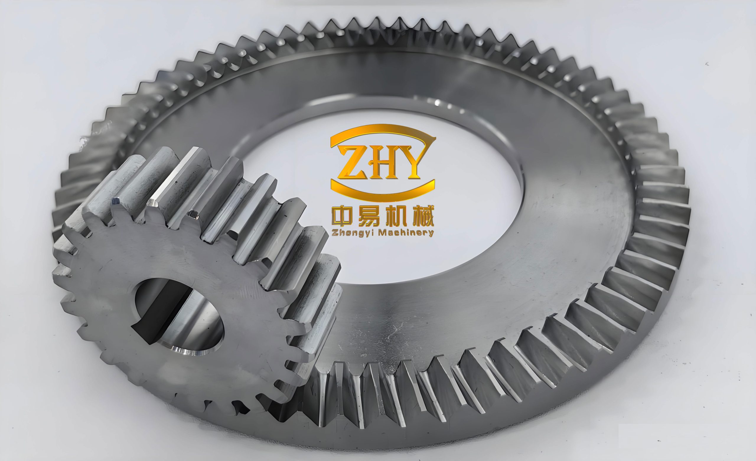
To evaluate the meshing performance of face gears, I use tooth contact analysis (TCA). The main indicators are the transmission error curve and the contact path on the face gear tooth surface. The transmission error reflects the smoothness of motion, while the contact path indicates the position, direction, and shape of the contact imprint. Assembly errors alter the relative position of the pinion and the face gear, so they directly affect these indicators. I consider three assembly error types: axial intersection displacement error, shaft angle error, and axial offset error. For each type, I calculate the contact path and transmission error for modified face gears and compare the results with the unmodified case. The findings provide a theoretical basis for the installation and application of face gear transmissions.
Tooth surface geometry of the face gear pair
The face gear pair consists of a face gear and a cylindrical pinion. The face gear is generated by a shaper cutter, while the pinion is generated by a rack cutter. In my derivation, the rack cutter is designed with a parabolic profile. The coordinate system for the rack profile is denoted by \(o_{ti}-x_{ti}y_{ti}z_{ti}\), and the rack coordinate system is \(o_{ri}-x_{ri}y_{ri}z_{ri}\). The subscript \(i\) takes the value 1 for the pinion and the value \(s\) for the shaper cutter. The pressure angle is \(\alpha_d\), and \(l_r\) is the distance between the origins of the two coordinate systems. The position vector of a point on the rack tooth surface in the profile coordinate system can be written as:
$$ \mathbf{r}_{ti}(u_{di},\theta_{di}) = \begin{bmatrix} u_{di} – u_{d0} \\ \alpha_{di} u_{di}^2 \\ \theta_{di} \\ 1 \end{bmatrix} $$
Here, \(\theta_{di}\) and \(u_{di}\) are the rack tooth surface variables, \(\alpha_{di}\) is the parabolic coefficient of the tooth profile, and \(u_{d0}\) is the offset distance from the base profile node. The rack vector in the rack coordinate system is obtained by a coordinate transformation:
$$ \mathbf{r}_{ri} = \mathbf{M}_{rt} \mathbf{r}_{ti}(u_{di},\theta_{di}) $$
where \(\mathbf{M}_{rt}\) is the transformation matrix from the profile coordinate system to the rack coordinate system. According to the generation principle, the cylindrical pinion tooth surface is the envelope of the rack tooth surface. For the pinion, the coordinate system \(o_1-x_1y_1z_1\) is fixed to the pinion, and \(o_n-x_ny_nz_n\) is an auxiliary coordinate system. The pinion rotation angle is \(\phi_1\), and the pitch radius of the pinion is \(r_{p1}\). The pinion tooth surface equation is:
$$ \mathbf{r}_1(u_{d1},\theta_{d1},\phi_1) = \mathbf{M}_{1n} \mathbf{M}_{nr}^{-1}(\phi_1) \mathbf{r}_{r1}(u_{d1},\theta_{d1}) $$
$$ f_1(u_{d1},\phi_1) = \mathbf{n}_{r1} \cdot \mathbf{v}_{r1} = 0 $$
In these equations, \(\mathbf{M}_{nr}^{-1}\) transforms from the rack coordinate system to the auxiliary coordinate system, \(\mathbf{M}_{1n}\) transforms from the auxiliary coordinate system to the pinion coordinate system, \(f_1\) is the meshing equation for the pinion, \(\mathbf{v}_{r1}\) is the relative velocity between the rack and the pinion, and \(\mathbf{n}_{r1}\) is the normal vector of the rack tooth surface. The same derivation applies to the face gear shaper cutter tooth surface. When \(i=s\), the equations produce the shaper cutter tooth surface, which is geometrically similar to the cylindrical pinion tooth surface.
The face gear tooth surface is generated by a grinding wheel that simulates the shaper cutter. During grinding, the grinding wheel rotates about its own axis, while the face gear rotates about its own axis. At the same time, the grinding wheel swings about the virtual shaper cutter axis. The two motions follow a fixed ratio. To derive the face gear tooth surface, I establish the coordinate systems shown in my analysis. The face gear coordinate system is \(o_2-x_2y_2z_2\), the shaper cutter coordinate system is \(o_s-x_sy_sz_s\), and the grinding wheel coordinate system is \(o_w-x_wy_wz_w\). Auxiliary coordinate systems \(o_a-x_ay_az_a\) and \(o_m-x_my_mz_m\) are used to simulate the positional relationship. The angle between the shaper cutter axis and the face gear axis is \(\gamma_m\), and \(E_w\) and \(R_s\) are the distances between the origins. The face gear tooth surface equation is:
$$ \mathbf{r}_2(u_{ds},\theta_{ds},\phi_s) = \mathbf{M}_{2m}\mathbf{M}_{ma}\mathbf{M}_{as}\mathbf{r}_s(u_{ds},\theta_{ds},\phi_s) $$
$$ f_2(u_{ds},\phi_s) = \mathbf{n}_{rs} \cdot \mathbf{v}_{rs} = 0 $$
Here, \(\mathbf{M}_{as}\) transforms from the shaper cutter coordinate system to the auxiliary coordinate system \(o_a-x_ay_az_a\), \(\mathbf{M}_{ma}\) transforms from \(o_a-x_ay_az_a\) to \(o_m-x_my_mz_m\), and \(\mathbf{M}_{2m}\) transforms from \(o_m-x_my_mz_m\) to the face gear coordinate system \(o_2-x_2y_2z_2\). \(f_2\) is the meshing equation for the face gear, \(\mathbf{v}_{rs}\) is the relative velocity between the shaper cutter and the face gear, and \(\mathbf{n}_{rs}\) is the normal vector of the shaper cutter tooth surface. These equations form the geometric foundation for the contact analysis of face gears.
Parabolic modification of the cylindrical pinion
The cylindrical pinion is ground by a forming wheel. The grinding wheel profile in the axial section is identical to the pinion tooth profile. The coordinate systems are \(o_1-x_1y_1z_1\) for the pinion and \(o_k-x_ky_kz_k\) for the grinding wheel. In the axial section, the pinion profile in the \(x_1y_1\) plane at \(z_1=0\) is:
$$ \mathbf{r}_{10} = [r_{1x}, r_{1y}, 0, 1]^T $$
where \(r_{1x}\) and \(r_{1y}\) are the components of the pinion tooth surface vector. By coordinate transformation, the axial profile of the grinding wheel is obtained as:
$$ \mathbf{r}_{k0} = \mathbf{M}_{k1} \mathbf{r}_{10} $$
where \(\mathbf{M}_{k1}\) is the transformation matrix from the pinion coordinate system to the grinding wheel coordinate system. The grinding wheel tooth surface is generated by rotating this axial profile about the wheel axis. Its vector expression is:
$$ \mathbf{r}_l = \mathbf{M}_{lk}\mathbf{M}_{k1}\mathbf{r}_{10} $$
where \(\mathbf{M}_{lk}\) transforms from the grinding wheel coordinate system to an auxiliary coordinate system. The tooth flank modification of the pinion is achieved by a parabolic motion of the grinding wheel center along the tooth width direction. After this modification, a crowning shape is formed in the tooth width direction. The auxiliary coordinate system \(o_g-x_gy_gz_g\) is fixed to the modified grinding wheel. The parabolic coefficient is \(\alpha_2\), the parabolic parameter is \(u_2\), the offset from the base node is \(u\), and \(\xi_k\) is the motion trajectory of the grinding wheel center in the \(y_1z_1\) plane. The modified pinion tooth surface is generated by the envelope of the modified grinding wheel surface:
$$ \mathbf{r}’_1 = \mathbf{M}_{1k}\mathbf{M}_{kg}\mathbf{r}_l $$
$$ f_k = \mathbf{n}_k \cdot \mathbf{v}_k = 0 $$
Here, \(\mathbf{r}’_1\) is the double-modified pinion tooth surface vector, \(\mathbf{M}_{kg}\) transforms from \(o_g-x_gy_gz_g\) to \(o_k-x_ky_kz_k\), \(\mathbf{M}_{1k}\) transforms from the grinding wheel coordinate system to the pinion coordinate system, \(f_k\) is the meshing equation, \(\mathbf{n}_k\) is the normal vector of the grinding wheel tooth surface, and \(\mathbf{v}_k\) is the relative velocity between the grinding wheel and the pinion tooth surface. The pinion tooth surface shape is determined by the profile parabolic coefficient \(\alpha_{d1}\), the base node offset \(u_{d0}\), the pressure angle \(\alpha_d\), the flank modification parabolic coefficient \(\alpha_2\), and the flank modification vertex offset \(u_d\). By changing these parameters, I can control the meshing performance of face gears.
Assembly error model and tooth contact analysis
To analyze the influence of assembly errors on the meshing performance of face gears, I establish a TCA coordinate system. The coordinate systems are \(o_h-x_hy_hz_h\) for the frame, \(o_2-x_2y_2z_2\) for the face gear, and \(o_1-x_1y_1z_1\) for the cylindrical pinion. The face gear and pinion rotate about \(z_2\) and \(z_1\), respectively. Auxiliary coordinate systems \(o_f-x_fy_fz_f\), \(o_q-x_qy_qz_q\), \(o_e-x_ey_ez_e\), and \(o_d-x_dy_dz_d\) are used to model the assembly relationship. The distance from \(o_f\) to \(o_1\) is \(R_f\), the pinion rotation angle is \(\phi’_1\), the face gear rotation angle is \(\phi’_2\), the angle between \(z_q\) and \(z_d\) is \(\gamma_f\), and the distance between \(z_q\) and \(z_f\) is \(B\). The assembly relations are:
$$ R_f = R_s + B \cot \gamma $$
$$ \gamma_f = \gamma_m + \Delta \gamma $$
In my model, \(\Delta E\) is the axial intersection displacement error, \(\Delta q\) is the axial offset error, and \(\Delta \gamma\) is the shaft angle error. To determine the contact condition, I transform both tooth surface equations into the frame coordinate system \(o_f-x_fy_fz_f\). For continuous contact of face gears, the position vectors and normal vectors must satisfy the following conditions:
$$ \mathbf{r}_{1f}(u_1,\theta_1,\phi’_1) = \mathbf{r}_{2f}(u_2,\theta_2,\phi’_2) $$
$$ \mathbf{n}_{1f} = \lambda \mathbf{n}_{2f} $$
$$ \mathbf{n}_{1f} \cdot \mathbf{v}_{12}^{(f)} = 0 $$
These equations yield five independent nonlinear equations with six unknown parameters. When \(\phi’_2\) is treated as the input parameter, the other five unknowns can be solved. This provides the complete data for a point contact of the meshing teeth. The transmission error is calculated from:
$$ \Delta \phi’_2 = \phi’_2 – \frac{z_1}{z_2}(\phi’_1 – \phi^{(0)}_1) $$
where \(z_1\) and \(z_2\) are the tooth numbers of the pinion and the face gear, respectively, and \(\phi^{(0)}_1\) is the value of \(\phi’_1\) when \(\phi’_2=0\). For my numerical study, I use the structural parameters of a face gear pair listed in Table 1.
| Number | Parameter | Symbol | Value | Unit |
|---|---|---|---|---|
| 1 | Cylindrical pinion tooth number | \(z_1\) | 22 | – |
| 2 | Face gear tooth number | \(z_2\) | 89 | – |
| 3 | Maximum outer radius | \(R_2\) | 151 | mm |
| 4 | Minimum inner radius | \(R_1\) | 129 | mm |
| 5 | Pressure angle | \(\alpha\) | 20 | degree |
| 6 | Shaft angle | \(\gamma_m\) | 90 | degree |
| 7 | Module | \(m\) | 3 | mm |
| 8 | Addendum coefficient of pinion | \(h_{a1}\) | 1.00 | – |
| 9 | Dedendum coefficient of pinion | \(h_{f1}\) | 1.25 | – |
Baseline behavior of unmodified face gears under combined assembly errors
Before evaluating modified face gears, I first calculate the meshing behavior of unmodified face gears with combined assembly errors. In most practical installations, all three errors can exist simultaneously. Therefore, I set the axial offset error \(\Delta q=0.2\) mm, the shaft angle error \(\Delta \gamma=0.02^\circ\), and the axial intersection displacement error \(\Delta E=0.2\) mm. The transmission error and contact path are computed by TCA. For unmodified face gears, the transmission error curve remains nearly a horizontal line, and its amplitude stays close to zero. This means the combined assembly errors have little effect on the transmission error of unmodified face gears. However, the contact path is strongly affected. Without assembly errors, the contact imprint is close to the inner end of the tooth surface, that is, near the minimum radius. With combined assembly errors, the contact imprint shifts along the tooth width direction toward the outer end. In both cases, the contact path is approximately perpendicular to the root cone, which indicates a high possibility of edge contact during operation. These results are summarized in Table 2.
| Configuration | Contact path position | Contact path direction | Transmission error shape | Edge contact risk |
|---|---|---|---|---|
| Unmodified, no assembly error | Near inner end | Perpendicular to root cone | Line, nearly zero amplitude | High |
| Unmodified, combined assembly error | Shifted toward outer end | Perpendicular to root cone | Line, nearly zero amplitude | Very high |
Modified face gears without assembly errors
To improve the meshing performance of face gears, I apply a double parabolic modification to the pinion tooth surface. The modification parameters are given in Table 3. Among these parameters, the pressure angle \(\alpha_d\) is selected during design, while the other parameters can be realized by numerical control machining. When assembly errors are not considered, the TCA results for modified face gears show a clear improvement. The contact imprint moves toward the middle of the face gear tooth surface. The contact path becomes tilted, which reduces the possibility of edge contact and increases the contact ratio. At the same time, the transmission error curve changes from a straight line into a parabolic curve. This parabolic shape helps reduce vibration and noise, because the motion error is smooth and continuous. These results confirm that double parabolic modification of the pinion is an effective way to improve the meshing behavior of face gears.
| Parameter | Symbol | Value | Unit |
|---|---|---|---|
| Profile parabolic coefficient | \(\alpha_{d1}\) | -0.03 | – |
| Flank parabolic coefficient | \(\alpha_2\) | 0.03 | – |
| Base profile node offset | \(u_{d0}\) | 0 | mm |
| Flank modification vertex offset | \(u_d\) | 0 | mm |
| Pressure angle | \(\alpha_d\) | 20 | degree |
Influence of axial intersection displacement error on modified face gears
I now analyze how each assembly error affects the modified face gears. The first case is the axial intersection displacement error \(\Delta E\). In this case, I set the shaft angle error and the axial offset error to zero. The axial intersection displacement error takes the values 0, 0.5 mm, and 1.0 mm, as shown in Table 4. The TCA results show that the axial intersection displacement error has little effect on the inclination of the contact path. Therefore, the contact ratio of face gears remains nearly unchanged. However, as the error increases, the contact imprint moves toward the tooth tip. The transmission error curve becomes steeper and discontinuous, and the transmission error amplitude increases. The larger the axial intersection displacement error, the higher the possibility of edge contact and the worse the meshing performance of face gears. This behavior is summarized in Table 5.
| Case | \(\Delta E\) (mm) | \(\Delta q\) (mm) | \(\Delta \gamma\) (rad) |
|---|---|---|---|
| I | 0 | 0 | 0 |
| II | 0.5 | 0 | 0 |
| III | 1.0 | 0 | 0 |
| Error type | Contact path position | Contact path inclination | Transmission error amplitude | Transmission error shape |
|---|---|---|---|---|
| Axial intersection displacement \(\Delta E\) | Moves toward tooth tip | Almost unchanged | Increases | Steep and discontinuous |
Influence of shaft angle error on modified face gears
The second case is the shaft angle error \(\Delta \gamma\). In this case, I set the axial intersection displacement error and the axial offset error to zero. The shaft angle error takes the values 0, 0.05 rad, and 0.10 rad, as shown in Table 6. The results show that the shaft angle error also has little effect on the inclination of the contact path. However, its effect on the contact position is opposite to that of the axial intersection displacement error. As the shaft angle error increases, the contact imprint moves toward the tooth root. The transmission error curve becomes steep and discontinuous, and the transmission error amplitude increases. This behavior is similar to the effect of the axial intersection displacement error in terms of transmission error amplitude. The larger the shaft angle error, the larger the transmission error amplitude and the worse the smoothness of face gear transmission. These results are summarized in Table 7.
| Case | \(\Delta E\) (mm) | \(\Delta q\) (mm) | \(\Delta \gamma\) (rad) |
|---|---|---|---|
| I | 0 | 0 | 0 |
| II | 0 | 0 | 0.05 |
| III | 0 | 0 | 0.10 |
| Error type | Contact path position | Contact path inclination | Transmission error amplitude | Transmission error shape |
|---|---|---|---|---|
| Shaft angle error \(\Delta \gamma\) | Moves toward tooth root | Almost unchanged | Increases | Steep and discontinuous |
Influence of axial offset error on modified face gears
The third case is the axial offset error \(\Delta q\). In this case, I set the axial intersection displacement error and the shaft angle error to zero. The axial offset error takes the values 0, 0.1 mm, and 0.2 mm, as shown in Table 8. The results show that the axial offset error does not affect the inclination of the contact path. However, as the axial offset error increases, the contact path moves toward the tooth root. The transmission error curve becomes an asymmetric parabola, and the transmission error amplitude increases. This indicates that the axial offset error has a relatively small effect on the contact path but a significant effect on the transmission error amplitude and the shape of the transmission error curve. These results are summarized in Table 9.
| Case | \(\Delta E\) (mm) | \(\Delta q\) (mm) | \(\Delta \gamma\) (rad) |
|---|---|---|---|
| I | 0 | 0 | 0 |
| II | 0 | 0.1 | 0 |
| III | 0 | 0.2 | 0 |
| Error type | Contact path position | Contact path inclination | Transmission error amplitude | Transmission error shape |
|---|---|---|---|---|
| Axial offset error \(\Delta q\) | Moves toward tooth root | Almost unchanged | Increases | Asymmetric parabola |
Comparison of unmodified and modified face gears under assembly errors
To make the influence of modification clear, I compare unmodified and modified face gears under assembly errors. The comparison is presented in Table 10. For unmodified face gears, the contact path is perpendicular to the root cone both with and without assembly errors. The transmission error remains a straight line, but the contact position is highly sensitive to assembly errors. In particular, combined assembly errors shift the contact imprint toward the outer end, increasing the risk of edge contact. For modified face gears, the contact path is tilted even without assembly errors, and the contact imprint is located near the middle of the tooth surface. When assembly errors are introduced, the contact path inclination is almost unchanged, and the contact position shifts only slightly. The transmission error curve remains parabolic, although its amplitude increases. This means that the double parabolic modification of the pinion reduces the sensitivity of face gears to assembly errors while maintaining favorable meshing characteristics.
| Configuration | Contact path position | Contact path inclination | Transmission error shape | Edge contact risk |
|---|---|---|---|---|
| Unmodified, no assembly error | Near inner end | Perpendicular to root cone | Line | High |
| Unmodified, combined assembly error | Shifted toward outer end | Perpendicular to root cone | Line | Very high |
| Modified, no assembly error | Middle of tooth surface | Tilted | Parabola | Low |
| Modified, combined assembly error | Small shift | Tilted | Parabola with increased amplitude | Low |
Summary of assembly error effects on modified face gears
The overall effects of the three assembly errors on modified face gears are summarized in Table 11. The axial intersection displacement error \(\Delta E\) moves the contact imprint toward the tooth tip and increases the transmission error amplitude. The shaft angle error \(\Delta \gamma\) moves the contact imprint toward the tooth root and also increases the transmission error amplitude. The axial offset error \(\Delta q\) moves the contact imprint toward the tooth root and changes the transmission error curve into an asymmetric parabola. In all three cases, the contact path inclination is only slightly affected. This is an important finding because it shows that the double parabolic modification of the pinion makes the contact path stable against assembly errors. The transmission error amplitude, however, still increases with the assembly error, which means that the smoothness of motion can deteriorate if the assembly errors become too large.
| Error type | Contact path shift | Transmission error amplitude | Transmission error shape | Sensitivity of face gears |
|---|---|---|---|---|
| Axial intersection displacement \(\Delta E\) | Toward tooth tip | Increases | Steep and discontinuous | Moderate |
| Shaft angle error \(\Delta \gamma\) | Toward tooth root | Increases | Steep and discontinuous | Moderate |
| Axial offset error \(\Delta q\) | Toward tooth root | Increases | Asymmetric parabola | Moderate |
Discussion of the meshing mechanism
The results I obtained can be explained by the geometric relationship between the modified pinion tooth surface and the face gear tooth surface. The double parabolic modification creates a localized contact region that is less sensitive to small changes in the relative position of the two members. The profile modification controls the contact along the tooth height, while the flank modification controls the contact along the tooth width. When the pinion and face gear are assembled with errors, the modification prevents the contact from moving abruptly to the tooth edges. Instead, the contact remains within the modified zone, and the transmission error changes gradually. This is why the contact path inclination remains nearly constant and the edge contact risk remains low. However, the modification cannot completely eliminate the effect of assembly errors on the transmission error amplitude. As the assembly error increases, the contact point moves away from the designed reference position, and the transmission error amplitude grows. This behavior is consistent with the nonlinear relationship between the contact point location and the transmission error.
For face gears, the axial intersection displacement error and the shaft angle error have opposite effects on the contact position. The axial intersection displacement error moves the contact toward the tooth tip, while the shaft angle error moves it toward the tooth root. If both errors exist simultaneously, their effects may partially cancel each other. This suggests that a careful adjustment of the assembly can be used to tune the contact position of face gears. The axial offset error, on the other hand, mainly changes the transmission error shape. It does not significantly change the contact path inclination, but it can make the transmission error curve asymmetric. An asymmetric transmission error curve may cause uneven loading and vibration, so the axial offset error should be controlled within a reasonable range in practical applications of face gears.
Implications for installation and application of face gears
My analysis provides several implications for the installation and application of face gears. First, the double parabolic modification of the pinion should be designed with appropriate coefficients so that the contact path is tilted and the transmission error is parabolic. This improves the baseline meshing performance of face gears and reduces the edge contact risk. Second, assembly errors should be controlled during installation. Although the modification reduces the sensitivity of the contact path to assembly errors, the transmission error amplitude still increases with the assembly error. Therefore, the axial intersection displacement error, shaft angle error, and axial offset error should be kept as small as possible. Third, if the contact position needs to be adjusted, the axial intersection displacement error and the shaft angle error can be used because they move the contact in opposite directions along the tooth height. This provides a practical way to fine-tune the contact pattern of face gears after assembly.
Mathematical summary of the contact and error relations
For completeness, I summarize the main mathematical relations used in my analysis. The pinion tooth surface is generated by the rack cutter:
$$ \mathbf{r}_1(u_{d1},\theta_{d1},\phi_1) = \mathbf{M}_{1n} \mathbf{M}_{nr}^{-1}(\phi_1) \mathbf{r}_{r1}(u_{d1},\theta_{d1}) $$
$$ f_1(u_{d1},\phi_1) = \mathbf{n}_{r1} \cdot \mathbf{v}_{r1} = 0 $$
The face gear tooth surface is generated by the shaper cutter or grinding wheel:
$$ \mathbf{r}_2(u_{ds},\theta_{ds},\phi_s) = \mathbf{M}_{2m}\mathbf{M}_{ma}\mathbf{M}_{as}\mathbf{r}_s(u_{ds},\theta_{ds},\phi_s) $$
$$ f_2(u_{ds},\phi_s) = \mathbf{n}_{rs} \cdot \mathbf{v}_{rs} = 0 $$
The modified pinion tooth surface is obtained by the parabolic motion of the grinding wheel:
$$ \mathbf{r}’_1 = \mathbf{M}_{1k}\mathbf{M}_{kg}\mathbf{r}_l $$
$$ f_k = \mathbf{n}_k \cdot \mathbf{v}_k = 0 $$
The contact condition for face gears is:
$$ \mathbf{r}_{1f}(u_1,\theta_1,\phi’_1) = \mathbf{r}_{2f}(u_2,\theta_2,\phi’_2) $$
$$ \mathbf{n}_{1f} = \lambda \mathbf{n}_{2f} $$
$$ \mathbf{n}_{1f} \cdot \mathbf{v}_{12}^{(f)} = 0 $$
The transmission error is:
$$ \Delta \phi’_2 = \phi’_2 – \frac{z_1}{z_2}(\phi’_1 – \phi^{(0)}_1) $$
These equations form the basis of the tooth contact analysis for face gears with assembly errors. By solving them numerically, I can obtain the contact path and transmission error for any combination of assembly errors and modification parameters.
Parametric study of modification coefficients
Although my main focus is on assembly errors, the modification coefficients also play an important role in the meshing performance of face gears. A larger profile parabolic coefficient \(\alpha_{d1}\) increases the curvature of the tooth profile, which can make the contact region narrower. A larger flank parabolic coefficient \(\alpha_2\) increases the crowning in the tooth width direction, which can reduce the edge contact risk but may also reduce the contact area. Therefore, the modification coefficients should be selected to balance the contact area and the sensitivity to assembly errors. In my analysis, the values \(\alpha_{d1}=-0.03\) and \(\alpha_2=0.03\) provide a good compromise for the given face gear pair. These values produce a tilted contact path, a parabolic transmission error, and a contact imprint near the middle of the tooth surface. If the assembly errors are expected to be large, the modification coefficients can be increased to further reduce the edge contact risk, but this may increase the transmission error amplitude.
Effect of tooth number difference
The tooth number difference between the shaper cutter and the pinion also affects the meshing performance of face gears. In my study, the pinion has 22 teeth and the face gear has 89 teeth. The shaper cutter is assumed to have a slightly different tooth number from the pinion, which creates local conjugation. The combination of local conjugation and double parabolic modification produces a contact pattern that is relatively stable against assembly errors. If the tooth number difference is too small, the contact may become too sensitive to assembly errors. If the tooth number difference is too large, the contact ratio may decrease. Therefore, the tooth number difference should be chosen according to the desired contact ratio and sensitivity. My results show that the double parabolic modification can compensate for the sensitivity caused by a small tooth number difference and improve the overall meshing performance of face gears.
Numerical solution procedure
The numerical solution procedure I use for the TCA of face gears is as follows. First, I define the geometric parameters of the pinion, the face gear, and the shaper cutter. Second, I derive the tooth surface equations for the pinion and the face gear using the coordinate transformations described above. Third, I apply the double parabolic modification to the pinion tooth surface by specifying the modification coefficients. Fourth, I introduce the assembly errors \(\Delta E\), \(\Delta q\), and \(\Delta \gamma\) into the TCA coordinate system. Fifth, I transform the tooth surface equations into the frame coordinate system and set up the contact equations. Sixth, I solve the nonlinear equations for a sequence of input rotation angles \(\phi’_2\). Finally, I compute the transmission error and the contact path from the solutions. This procedure allows me to evaluate the meshing performance of face gears under different assembly conditions and modification parameters.
Interpretation of transmission error curves
The transmission error curve is an important indicator of the smoothness of face gear transmission. For unmodified face gears, the transmission error curve is a straight line with nearly zero amplitude. This indicates that the motion transmission is theoretically perfect, but the contact is highly sensitive to assembly errors. For modified face gears without assembly errors, the transmission error curve is a parabola. The parabolic shape means that the transmission error changes smoothly with the rotation angle, which is beneficial for reducing vibration and noise. When assembly errors are introduced, the transmission error curve remains parabolic but its amplitude increases. For the axial intersection displacement error and the shaft angle error, the curve becomes steep and discontinuous. For the axial offset error, the curve becomes an asymmetric parabola. These changes indicate that the assembly errors degrade the smoothness of face gear transmission, even though the contact path inclination is not strongly affected.
Contact path and edge contact risk
The contact path is another important indicator of the meshing performance of face gears. For unmodified face gears, the contact path is perpendicular to the root cone, which means that the contact moves across the tooth width in a direction that is not favorable for avoiding edge contact. When assembly errors are present, the contact path shifts toward the outer end, increasing the edge contact risk. For modified face gears, the contact path is tilted. The tilt directs the contact away from the tooth edges and toward the middle of the tooth surface. This reduces the edge contact risk and improves the load distribution. When assembly errors are introduced, the contact path inclination remains nearly unchanged, which means that the modification maintains its beneficial effect. The contact position may shift slightly, but the edge contact risk remains low. This is one of the main advantages of the double parabolic modification for face gears.
Design recommendations
Based on my analysis, I recommend the following design and installation practices for face gears. The pinion should be modified with both profile and flank parabolic coefficients. The profile modification should be designed to control the contact along the tooth height, and the flank modification should be designed to control the contact along the tooth width. The modification coefficients should be selected so that the contact path is tilted and the transmission error is parabolic. During installation, the axial intersection displacement error, shaft angle error, and axial offset error should be measured and controlled. The axial intersection displacement error and shaft angle error should be kept small because they increase the transmission error amplitude and can cause discontinuous transmission error. The axial offset error should also be kept small because it can make the transmission error curve asymmetric. If fine adjustment is needed, the axial intersection displacement error and the shaft angle error can be used to move the contact position in opposite directions. This provides a practical method for optimizing the contact pattern of face gears after assembly.
Concluding remarks
In my study, I investigated the influence of assembly errors on the meshing performance of modified face gears. I derived the tooth surface equations for the pinion and the face gear, applied a double parabolic modification to the pinion, and simulated three types of assembly errors. The main conclusions are as follows. First, without assembly errors, the double parabolic modification moves the contact imprint toward the middle of the face gear tooth surface, tilts the contact path, and changes the transmission error from a straight line to a parabola. This reduces the edge contact risk and improves the smoothness of face gear transmission. Second, the three assembly errors have different effects on the contact position and transmission error. The axial intersection displacement error moves the contact toward the tooth tip, the shaft angle error moves it toward the tooth root, and the axial offset error moves it toward the tooth root. All three errors increase the transmission error amplitude. Third, the double parabolic modification reduces the sensitivity of the contact path to assembly errors. The contact path inclination remains nearly unchanged, and the edge contact risk remains low even when assembly errors are present. However, the transmission error amplitude still increases with the assembly error, so assembly errors should be controlled within a reasonable range. These findings provide a theoretical basis for the installation and application of face gears in practical transmissions.
Final summary tables
For quick reference, I provide two final summary tables. Table 12 summarizes the key equations used in my analysis. Table 13 summarizes the main qualitative effects of assembly errors on modified face gears.
| Quantity | Equation |
|---|---|
| Rack tooth surface | \(\mathbf{r}_{ti}(u_{di},\theta_{di}) = [u_{di}-u_{d0}, \alpha_{di}u_{di}^2, \theta_{di}, 1]^T\) |
| Pinion tooth surface | \(\mathbf{r}_1 = \mathbf{M}_{1n}\mathbf{M}_{nr}^{-1}\mathbf{r}_{r1}\), \(f_1 = \mathbf{n}_{r1}\cdot\mathbf{v}_{r1}=0\) |
| Face gear tooth surface | \(\mathbf{r}_2 = \mathbf{M}_{2m}\mathbf{M}_{ma}\mathbf{M}_{as}\mathbf{r}_s\), \(f_2 = \mathbf{n}_{rs}\cdot\mathbf{v}_{rs}=0\) |
| Modified pinion surface | \(\mathbf{r}’_1 = \mathbf{M}_{1k}\mathbf{M}_{kg}\mathbf{r}_l\), \(f_k = \mathbf{n}_k\cdot\mathbf{v}_k=0\) |
| Contact condition | \(\mathbf{r}_{1f}=\mathbf{r}_{2f}\), \(\mathbf{n}_{1f}=\lambda\mathbf{n}_{2f}\), \(\mathbf{n}_{1f}\cdot\mathbf{v}_{12}^{(f)}=0\) |
| Transmission error | \(\Delta\phi’_2 = \phi’_2 – \frac{z_1}{z_2}(\phi’_1-\phi^{(0)}_1)\) |
| Assembly relation | \(R_f = R_s + B\cot\gamma\), \(\gamma_f = \gamma_m + \Delta\gamma\) |
| Error type | Contact position | Contact path tilt | Transmission error amplitude | Transmission error shape | Overall effect on face gears |
|---|---|---|---|---|---|
| Axial intersection displacement \(\Delta E\) | Toward tooth tip | Nearly unchanged | Increases | Steep and discontinuous | Degrades smoothness |
| Shaft angle error \(\Delta \gamma\) | Toward tooth root | Nearly unchanged | Increases | Steep and discontinuous | Degrades smoothness |
| Axial offset error \(\Delta q\) | Toward tooth root | Nearly unchanged | Increases | Asymmetric parabola | Degrades smoothness |
In summary, my first-person investigation shows that the double parabolic modification of the pinion is an effective method for improving the meshing performance of face gears. It reduces the sensitivity of the contact path to assembly errors, lowers the edge contact risk, and produces a smooth parabolic transmission error. Nevertheless, assembly errors still increase the transmission error amplitude and can change the shape of the transmission error curve. Therefore, precise assembly remains important for face gears. The equations, tables, and qualitative trends presented here can be used as a guide for the design, analysis, and installation of face gear transmissions.