
I approached this study as a practical design, analysis, and verification task for the drive axle of a mini car. My central object was the hypoid bevel gear pair used in the main reducer, because hypoid bevel gears dominate the transmission quality, load capacity, vibration behavior, and acoustic performance of a rear-drive mini-car axle. I wanted to move beyond a purely empirical axle design method and combine parameter calculation, gear design software, system-level transmission analysis, and fault detection. In my work, the hypoid bevel gears were not treated as isolated parts. Instead, I treated them as the core of a coupled mechanical system that includes shafts, bearings, the housing, lubricant, and the vehicle load spectrum. This first-person account describes the design logic, the mathematical background, the optimization decisions, the simulation results, and the test system I developed for quality verification.
The motivation for focusing on hypoid bevel gears is straightforward. A drive axle transfers engine torque to the wheels while providing the final speed reduction and differential action. In a mini car, the main reducer usually uses a single-stage hypoid bevel gear set. These gears allow the pinion axis and the ring gear axis to be offset, which gives the vehicle layout greater freedom, lowers the driveline tunnel, increases ground clearance when the offset is upward, and improves the strength of the pinion when the offset is downward. The offset also increases the spiral angle of the pinion, which can raise the contact ratio and reduce contact stress. At the same time, hypoid bevel gears introduce relative sliding along both the tooth length and tooth height, so lubrication, heat generation, and surface durability must be considered carefully. My design therefore had to balance strength, life, noise, and manufacturability.
I began with the vehicle-level inputs. The mini car had a maximum engine torque, several transmission ratios, a final drive ratio, a wheel rolling radius, axle loads, and a wheelbase. These values defined the torque seen by the hypoid bevel gears and the structural envelope of the axle. I first computed the torque on the ring gear under the worst low-gear condition and then compared it with the torque limit set by tire adhesion. This comparison prevented me from sizing the hypoid bevel gears only for engine torque while ignoring the traction limit. In my calculation, the maximum engine torque was used together with the first-gear ratio, the final drive ratio, an overload factor, and a transmission efficiency.
$$T_{je}=T_{e\max} i_{g1} i_0 K_0 \eta_T$$
In this expression, \(T_{e\max}\) is the maximum engine torque, \(i_{g1}\) is the first-gear ratio, \(i_0\) is the main reduction ratio, \(K_0\) is an overload factor, and \(\eta_T\) is the transmission efficiency. For the mini-car axle I studied, the first-gear ratio was high enough that the hypoid bevel gears had to be checked against a torque significantly larger than the nominal engine torque. I also calculated the adhesion-limited torque transmitted to the ring gear, because a drive axle should not be designed for a torque that the tires cannot actually transmit. This is especially important for mini cars, whose rear axle load changes considerably with passenger and cargo conditions.
$$T_{j\varphi}=\frac{G_2 \varphi r \eta_{LB}}{i_{LB}}$$
Here \(G_2\) is the rear axle load, \(\varphi\) is the road adhesion coefficient, \(r\) is the wheel rolling radius, \(\eta_{LB}\) is the efficiency from the ring gear to the driven wheels, and \(i_{LB}\) is the corresponding reduction ratio. I took the design torque as the smaller of the engine-limited and adhesion-limited values. This gave me a rational starting point for the pitch diameter of the ring gear and for the subsequent sizing of the hypoid bevel gears.
| Vehicle or axle input | Value used in my study |
| Maximum engine output torque | 131 N·m |
| First-gear ratio | 3.857 |
| Second-gear ratio | 2.176 |
| Third-gear ratio | 1.419 |
| Fourth-gear ratio | 1.000 |
| Fifth-gear ratio | 0.808 |
| Reverse ratio | 4.128 |
| Main reduction ratio | 4.889 |
| Rear wheel track | 1440 mm |
| Wheelbase | 2720 mm |
| Front and rear axle loads | 700 kg / 1200 kg |
| Wheel rolling radius | 289 mm |
| Loaded center-of-gravity height | 700 mm |
After establishing the load case, I moved to the preliminary geometry of the hypoid bevel gears. The ring gear pitch diameter is the single most important envelope parameter because it controls the size of the main reducer, the ground clearance, and the available space for the axle housing. I used an empirical cube-root relationship to estimate the ring gear pitch diameter from the design torque.
$$d_2=K_{d2}\sqrt[3]{T_j}$$
In my first estimate, the diameter coefficient \(K_{d2}\) was allowed to vary between 13 and 16. This range produced two candidate ring gear diameters. I compared those candidates with the existing axle platform and the available housing dimensions. Because the mini car needed a compact axle with adequate ground clearance, I selected a diameter that balanced strength and package space. This decision was not based only on stress. It also considered the bearing span, the differential size, the half-shaft layout, and the manufacturing capability for the hypoid bevel gears.
| Diameter coefficient | Estimated ring gear pitch diameter |
| 13 | approximately 169.7 mm |
| 16 | approximately 208.8 mm |
| Selected design direction | compact diameter with adequate load capacity |
I then fixed the gear ratio at 9:44, which corresponds to a main reduction ratio of 4.889. The 9-tooth pinion is small, so I paid special attention to undercut, root strength, and the effect of the offset on the pinion spiral angle. The face width of the ring gear was another critical parameter. A wider face can reduce bending deflection and noise, but an excessively wide face can make the tooth slot too narrow at the small end, reduce cutter life, and amplify the influence of misalignment. I used an empirical relation for the face width and then checked it against the cone distance.
$$F=0.155 d_2$$
For the first layout, this produced a face width of approximately 31 mm. Later, during optimization, I reduced it to 28 mm to improve the ratio of face width to cone distance and to achieve a better life balance between the pinion and the ring gear. I found that the hypoid bevel gears behaved better when the face width was not pushed to the maximum possible value. The offset distance was also limited by the ring gear diameter. For a passenger-car or light commercial vehicle, I used the guideline that the offset should not exceed about 20 percent of the ring gear pitch diameter.
$$E\le 0.2 d_2$$
In my first design, I considered an offset near 30 mm. During optimization, I reduced the offset to 25 mm. This change lowered the relative sliding of the hypoid bevel gears, reduced heat generation, and made the contact pattern more stable under load. The smaller offset also made the axle package slightly more compact, although it required me to recheck the pinion strength and the contact ratio.
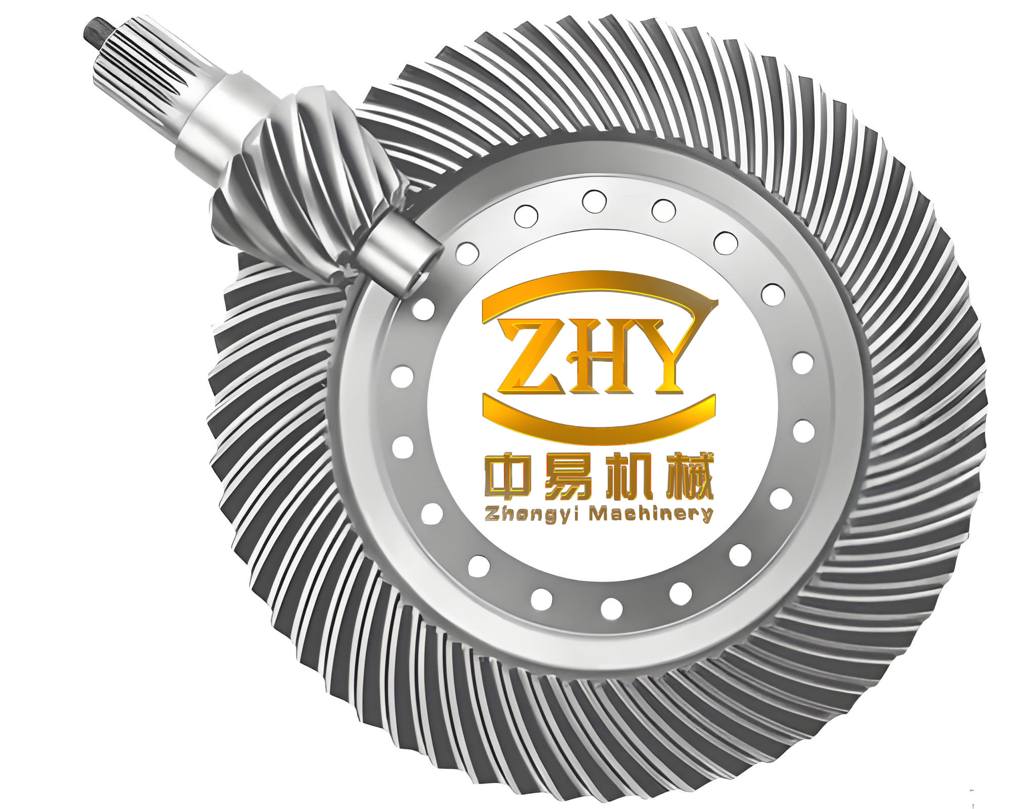
The spiral angle of the pinion is one of the most influential parameters in a hypoid bevel gear set. A larger spiral angle increases the contact ratio and the pinion diameter, but it also increases axial force, sliding velocity, and manufacturing difficulty. I used a recommended relationship that combines the number of teeth, the offset, and the ring gear diameter.
$$\beta_p=25.0+5.0\sqrt{\frac{N}{n}}+90.0\frac{E}{D}$$
Here \(N\) is the number of ring gear teeth, \(n\) is the number of pinion teeth, \(E\) is the offset, and \(D\) is the ring gear diameter. My initial estimate gave a pinion spiral angle slightly above 51 degrees. I then adjusted it to approximately 50 degrees for the first design and later to 49 degrees 15 minutes for the optimized design. This reduction improved the manufacturing feasibility of the hypoid bevel gears while maintaining a sufficiently high contact ratio. I also selected a left-hand spiral for the pinion and a right-hand spiral for the ring gear, which is a common arrangement for a rear-drive axle with a downward offset.
| Parameter | Initial design | Optimized design |
| Number of pinion teeth | 9 | 9 |
| Number of ring gear teeth | 44 | 44 |
| Main reduction ratio | 4.889 | 4.889 |
| Ring gear pitch diameter | about 178 mm | about 178 mm |
| Ring gear face width | 31 mm | 28 mm |
| Offset distance | 30 mm | 25 mm |
| Pinion spiral angle | about 50° | 49°15′ |
| Pressure angle | 38° combined | 38° combined |
| Pinion hand | left-hand | left-hand |
| Ring gear hand | right-hand | right-hand |
For the material and heat treatment of the hypoid bevel gears, I selected a carburizing alloy steel. The pinion and ring gear must resist bending fatigue, contact fatigue, wear, and occasional shock loads. The surface hardness must be high, while the core must retain enough toughness to prevent tooth breakage. I specified a case-hardened surface in the range of 58 to 64 HRC and a core hardness that depends on the module. I also considered shot peening and phosphating as surface treatments. Shot peening can improve fatigue life, while phosphating can improve running-in behavior and reduce the risk of scuffing in the early life of the hypoid bevel gears.
| Material and treatment item | Requirement in my design |
| Steel type | carburizing alloy steel |
| Surface hardness | 58–64 HRC |
| Core hardness | 32–45 HRC for small module, 29–45 HRC for larger module |
| Case depth | approximately 0.9–1.6 mm depending on module |
| Surface treatment | phosphating and possible shot peening |
| Main failure risks | pitting, wear, scuffing, bending fatigue, tooth breakage |
My design theory for the hypoid bevel gears followed a quasi-conjugate approach rather than strict theoretical conjugacy. A perfectly conjugate gear pair is sensitive to manufacturing and assembly errors, and such errors can destroy the intended contact pattern. In practical axle production, I needed a contact pattern that is tolerant to small misalignments. Therefore, I used a reference point where the cutter surface and the tooth surface are tangent, while other points have controlled mismatch. This is the basis of the local conjugate method and the tooth contact analysis used for hypoid bevel gears.
I described the cutter surface mathematically in the cutter coordinate system. For the pinion cutter and ring gear cutter, the surface position and the unit normal can be written as functions of cutter radius, cutter angle, and a surface parameter.
$$r_I=r_I(S_I,\theta_I)$$
$$n_I=n_I(\theta_I)$$
$$r_{II}=r_{II}(S_{II},\theta_{II})$$
$$n_{II}=n_{II}(\theta_{II})$$
For a cutter with radius \(r_c\), pressure angle \(\alpha\), and angular parameter \(\theta\), the position vector can be expressed in a form similar to the following.
$$r(S,\theta)=
\begin{bmatrix}
(r_c-S\sin\alpha)\cos\theta\\
(r_c-S\sin\alpha)\sin\theta\\
-S\cos\alpha\\
1
\end{bmatrix}$$
The corresponding normal vector is obtained from the derivatives of the surface with respect to the two surface parameters. I then transformed these surfaces from the cutter coordinate system to the gear coordinate system. This transformation involves a rotation matrix and a translation matrix. In symbolic form, the transformation can be written as follows.
$$r_M=P_{MI} r_I$$
$$n_M=Q_{MI} n_I$$
$$r_S=P_{SII} r_{II}$$
$$n_S=Q_{SII} n_{II}$$
For the meshing condition of the hypoid bevel gears, the position vectors and normal vectors of the two tooth surfaces must be equal at the instantaneous contact point when expressed in the same fixed coordinate system.
$$r_{Mh}=r_{Sh}$$
$$n_{Mh}=n_{Sh}$$
The instantaneous transmission ratio is not constant for a quasi-conjugate hypoid bevel gear pair. It is defined by the derivative of the ring gear rotation with respect to the pinion rotation.
$$i=\frac{d\varphi_S}{d\varphi_M}$$
I preferred a transmission ratio curve that is symmetric about the contact point rather than one that is symmetric about the center of the contact path. The symmetric-about-contact-point form allows the entry and exit transmission ratios to be equal, which reduces impact at the beginning and end of meshing. This detail is important for the acoustic quality of hypoid bevel gears because a sudden change in transmission ratio can excite the axle housing and produce whine.
| Design theory item | What I used it for |
| Quasi-conjugate tooth surface | tolerance to manufacturing and assembly errors |
| Reference point tangency | controlled contact pattern |
| Tooth contact analysis | contact path and transmission error prediction |
| Loaded tooth contact analysis | contact pattern and stress under torque |
| Transmission ratio curve | reduction of impact at mesh entry and exit |
| Undercut check | verification of the 9-tooth pinion |
I used a dedicated hypoid bevel gear design environment to calculate the basic parameters, the tooth proportions, the cutter settings, the machine settings, and the contact analysis. The design process was iterative. I first entered the required data, such as the product type, gear ratio, offset, face width, spiral angle, pressure angle, cutter diameter, and tooth depth coefficients. I then examined the calculated tooth proportions, sliding coefficients, contact ratio, and undercut risk. After that, I adjusted the contact coefficients and the vertical and horizontal wheel positions to move the contact pattern to a favorable location.
For the stress check, I used allowable bending stress and allowable contact stress as constraints. In my first design, the pinion bending stress was about 457 MPa and the contact stress was about 2502 MPa. Both were below the limits I had set. However, the first design still had three weaknesses. The life of the pinion and the life of the ring gear were not balanced. The ratio of face width to cone distance was about 0.4, which was higher than the desired value. The pinion spiral angle was slightly above 51 degrees, which increased manufacturing difficulty and heat treatment distortion. These findings led me to optimize the hypoid bevel gears rather than accept the first feasible design.
| Check item | First design result | Acceptance target |
| Pinion bending stress | about 457 MPa | below 690 MPa |
| Contact stress | about 2502 MPa | below 2800 MPa |
| Undercut | no undercut | no undercut |
| Face width to cone distance | about 0.40 | about 0.30 |
| Pinion spiral angle | above 51° | about 49°–50° |
| Life balance | not balanced | balanced pinion and ring gear life |
I then built a transmission system model to analyze the hypoid bevel gears in their real support and housing environment. A gear pair that looks acceptable in a standalone tooth contact analysis can still perform poorly when the shafts, bearings, and housing deflect under load. I used a system-level transmission analysis tool to include shaft stiffness, bearing stiffness, housing stiffness, and load distribution. The model contained the pinion, the ring gear, the differential, the bearings, and the housing. I applied the measured or estimated load spectrum at the pinion input and calculated the misalignment of the hypoid bevel gears under torque.
| Load spectrum item | First gear | Second gear | Third gear | Fourth gear | Fifth gear |
| Input torque (N·m) | 259.96 | 132.77 | 72.71 | 59.55 | 67.20 |
| Input speed (rpm) | 1637.88 | 2960.17 | 4504.50 | 5500.00 | 6823.82 |
| Operating time (h) | 40.60 | 67.40 | 59.05 | 60.46 | 68.22 |
| Durability bench load case | Value |
| Input torque | 400 N·m |
| Input speed | 500 rpm |
| Number of cycles | 500,000 |
| Equivalent running time | 16.67 h |
The system-level analysis gave me the misalignment of the hypoid bevel gears under load. I expressed the misalignment in terms of an angular deviation and three linear deviations. These values were then fed back into the tooth contact analysis so that I could see how the contact pattern and transmission error changed when the axle deflected. This feedback loop was essential. Without it, I would have optimized the hypoid bevel gears only for a rigid theoretical condition that does not exist in a real vehicle.
| Misalignment component | Reference value |
| Angular deviation | 0.001 mrad |
| Offset deviation | 292.81 μm |
| Pinion axial deviation | −266.69 μm |
| Wheel axial deviation | 384.41 μm |
I also examined the dynamic behavior of the axle. The transmission error of the hypoid bevel gears is a major excitation source for gear whine. I calculated the transmission error curve, applied a Fourier transform, and used the resulting harmonic content as an excitation input to the housing model. The first-order transmission error usually carries the largest energy, so I paid particular attention to it. In my analysis, the housing response showed that the first-order excitation was dominant, and the response peaks were concentrated at a low frequency that could produce a whine point. This told me that reducing the transmission error amplitude of the hypoid bevel gears would be more effective than simply increasing the housing stiffness everywhere.
$$E_{TE}(\varphi)=\varphi_S(\varphi_M)-i_0\varphi_M$$
In this equation, \(E_{TE}\) is the transmission error, \(\varphi_S\) is the actual ring gear rotation, \(\varphi_M\) is the pinion rotation, and \(i_0\) is the nominal ratio. I used the peak-to-peak value and the first harmonic amplitude of \(E_{TE}\) as NVH indicators. A smaller first harmonic generally means lower whine excitation from the hypoid bevel gears. I also used the contact pattern position as an indicator of robustness. A contact pattern that stays within the tooth surface under the full load spectrum is more desirable than a pattern that is perfectly centered only at a single load.
After the first simulation round, I changed three design variables. I reduced the ring gear face width from 31 mm to 28 mm. I reduced the offset from 30 mm to 25 mm. I changed the pinion spiral angle to 49 degrees 15 minutes. I then recalculated the tooth proportions, the contact pattern, the transmission error, and the stresses. The new design achieved a better balance between the pinion life and the ring gear life. The ratio of face width to cone distance became about 0.31, which was close to the target. The contact stress increased slightly compared with the first design, but it remained within the allowable range. The bending stress also remained acceptable. Most importantly, the new hypoid bevel gears had a more stable contact pattern under the system misalignment produced by the axle housing and bearings.
| Optimization variable | First design | Optimized design | Effect I observed |
| Ring gear face width | 31 mm | 28 mm | better face width to cone distance ratio |
| Offset distance | 30 mm | 25 mm | lower sliding and heat generation |
| Pinion spiral angle | about 50° | 49°15′ | easier manufacturing and heat treatment |
| Life balance | unbalanced | more balanced | improved durability potential |
| Contact stability | moderate | improved | better tolerance to misalignment |
I did not stop at simulation. I also developed a test system for the hypoid bevel gears so that the manufactured gears could be checked against the design intent. The test system was based on vibration measurement during a running-in test. The purpose was to detect abnormal meshing, local defects, and excessive noise excitation before the axle was assembled into the vehicle. The system included a test platform, sensors, a data acquisition card, a logic controller, a host computer, and signal analysis software. I chose a virtual instrument environment because it allowed me to integrate acquisition, display, and analysis in one interface.
| Test system part | Function |
| Test platform | supports the axle and applies running-in load |
| Vibration sensors | measure meshing vibration of the hypoid bevel gears |
| Data acquisition card | converts analog vibration signals into digital data |
| Logic controller | controls the test sequence and safety interlocks |
| Host computer | runs the analysis software and stores data |
| Signal analysis software | performs time-domain, frequency-domain, and wavelet analysis |
The test software contained four main modules: initialization, time-domain analysis, frequency-domain analysis, and fault judgment. In the initialization module, I set the sampling frequency, the number of samples, the data storage path, and the threshold values. The system could run in online mode for direct measurement or in offline mode for reanalysis of saved data. In the time-domain module, I calculated the root mean square, peak value, kurtosis, crest factor, and other statistical indicators. These indicators helped me detect impulsive events and abnormal vibration energy.
$$x_{rms}=\sqrt{\frac{1}{N}\sum_{i=0}^{N-1}x_i^2}$$
$$x_p=\max |x_i|$$
$$C_p=\frac{x_p}{x_{rms}}$$
$$K=\frac{\sum_{i=0}^{N-1}(x_i-\bar{x})^4}{N\sigma^4}$$
In my test results for the optimized hypoid bevel gears, the time-domain signal was relatively smooth and did not show large repetitive impacts. The root mean square was about 30.29, the peak value was about 131.97, the kurtosis was about 3.3, and the crest factor was about 4.33. These values indicated that the meshing was stable. A kurtosis close to 3 is typical of a signal without strong impulsive components, so the optimized hypoid bevel gears did not show obvious local tooth damage or severe meshing impact.
| Time-domain indicator | Measured value for optimized hypoid bevel gears |
| Root mean square | 30.29 |
| Peak value | 131.97 |
| Kurtosis | 3.30 |
| Crest factor | 4.33 |
| Signal character | smooth, low impact, stable meshing |
For frequency-domain analysis, I used the discrete Fourier transform to convert the vibration signal into the frequency domain. The amplitude spectrum and power spectrum revealed the mesh frequency and its sidebands. The mesh frequency of the hypoid bevel gears is determined by the pinion speed and the number of pinion teeth.
$$f_m=\frac{n_p n}{60}$$
In this expression, \(f_m\) is the mesh frequency, \(n_p\) is the pinion speed in revolutions per minute, and \(n\) is the number of pinion teeth. I also calculated the pinion rotation frequency and the ring gear rotation frequency because sidebands around the mesh frequency often indicate modulation caused by eccentricity, misalignment, or local tooth defects.
$$f_p=\frac{n_p}{60}$$
$$f_g=\frac{n_p}{60 i_0}$$
I used power spectrum analysis, zoom spectrum analysis, envelope demodulation, and wavelet packet decomposition. The power spectrum showed the energy distribution of the vibration signal. A well-designed hypoid bevel gear set should have a dominant mesh frequency but relatively low sideband amplitudes. In my measurements, the power spectrum had a clear mesh frequency peak, while the surrounding frequency components were low. This was a good indicator that the contact pattern and the running-in process were correct.
| Frequency-domain method | Purpose in my test system |
| Power spectrum | identify mesh frequency and dominant energy |
| Zoom spectrum | increase resolution near the mesh frequency |
| Envelope demodulation | extract modulation caused by local faults |
| Wavelet packet decomposition | analyze non-stationary and transient components |
| Sideband analysis | detect eccentricity and misalignment of hypoid bevel gears |
For envelope demodulation, I used the Hilbert transform. The analytic signal is formed by combining the real vibration signal with its Hilbert transform. The envelope is the magnitude of the analytic signal.
$$x_a(t)=x(t)+j\hat{x}(t)$$
$$A(t)=\sqrt{x^2(t)+\hat{x}^2(t)}$$
$$\phi(t)=\arctan\frac{\hat{x}(t)}{x(t)}$$
In the envelope spectrum, I found a component near the pinion rotation frequency. This did not indicate a severe fault because the amplitude was small, but it did show that the test system could detect low-frequency modulation. If the amplitude at the pinion or ring gear rotation frequency becomes large, I would interpret it as a sign of eccentricity, unbalance, or a local tooth defect in the hypoid bevel gears. This makes the test system useful not only for pass/fail inspection but also for guiding design improvements.
I also implemented wavelet packet decomposition for the vibration signal. The Fourier transform is global, so it is not ideal for transient events that occur over a short time interval. Wavelet packet decomposition can separate the signal into multiple frequency bands and preserve time localization. This is valuable for hypoid bevel gears because a small pit or a local contact error may produce a short impact that is hidden in the overall spectrum.
$$p_j^{2i}(t)=\sum_k H(k-2t)p_{j-1}^{i}(t)$$
$$p_j^{2i+1}(t)=\sum_k G(k-2t)p_{j-1}^{i}(t)$$
For reconstruction, the wavelet packet coefficients are upsampled and convolved with the reconstruction filters. I used this method to produce an envelope for selected frequency bands and then analyzed the envelope spectrum. In my test interface, I displayed the time waveform, the power spectrum, and the envelope demodulation result for each selected band. This gave me a practical way to distinguish between a global mesh problem and a local tooth problem in the hypoid bevel gears.
| Analysis domain | Indicator I monitored | Interpretation for hypoid bevel gears |
| Time domain | RMS, peak, kurtosis, crest factor | overall energy, impact severity, local damage risk |
| Power spectrum | mesh frequency amplitude, sidebands | meshing quality and modulation |
| Zoom spectrum | fine structure near mesh frequency | closely spaced sidebands and modulation sources |
| Envelope demodulation | rotation frequency amplitude | eccentricity, misalignment, local defects |
| Wavelet packet | band-limited transient energy | short impacts and non-stationary faults |
From the design side, I found that the most important parameters for the hypoid bevel gears were the offset, the spiral angle, the face width, the pressure angle, and the contact pattern. The offset changes the sliding condition and the pinion diameter. The spiral angle changes the contact ratio and the axial force. The face width changes the load distribution and the sensitivity to misalignment. The pressure angle changes the bending stress and the contact stress. The contact pattern determines whether the load is concentrated at the tooth ends or distributed across the tooth surface. I therefore evaluated these parameters together rather than optimizing them one by one.
| Parameter | Main effect on hypoid bevel gears | Risk if too large | Risk if too small |
| Offset | changes sliding, pinion diameter, layout | high sliding, heat, scuffing | less layout freedom, lower pinion strength |
| Spiral angle | changes contact ratio and axial force | high axial load, manufacturing difficulty | low contact ratio, noisy mesh |
| Face width | changes load capacity and deflection | narrow tooth slot, cutter problems | high bending deflection, lower strength |
| Pressure angle | changes bending and contact stress | higher separation force | lower bending strength, undercut risk |
| Contact pattern | changes stress distribution and noise | edge contact, early failure | insufficient contact area, high stress |
My final design used a 9-tooth left-hand pinion and a 44-tooth right-hand ring gear. The main reduction ratio was 4.889. The ring gear pitch diameter was kept within the compact axle envelope. The ring gear face width was 28 mm, the offset was 25 mm, and the pinion spiral angle was 49 degrees 15 minutes. The combined pressure angle was 38 degrees. The material was a carburizing alloy steel with a hard surface and a tough core. The contact analysis and loaded contact analysis showed that the contact pattern was acceptable under the system misalignment, and the stress levels were below the allowable limits. The optimized hypoid bevel gears also had a better life balance than the first design.
| Final design parameter | Value |
| Gear type | hypoid bevel gears |
| Pinion teeth | 9 |
| Ring gear teeth | 44 |
| Reduction ratio | 4.889 |
| Pinion hand | left-hand |
| Ring gear hand | right-hand |
| Ring gear face width | 28 mm |
| Offset | 25 mm |
| Pinion spiral angle | 49°15′ |
| Combined pressure angle | 38° |
| Material | carburizing alloy steel |
| Surface hardness | 58–64 HRC |
| Core hardness | 32–45 HRC depending on module |
| Main verification | TCA, LTCA, stress check, undercut check, system misalignment, NVH |
I also used the test system to compare the optimized hypoid bevel gears with the expected behavior. The time-domain waveform was smooth, the power spectrum was dominated by the mesh frequency, and the envelope spectrum had only a small low-frequency component. The zoom spectrum showed that the sidebands around the mesh frequency were weak. These results agreed with the design prediction. I interpreted this as evidence that the optimized hypoid bevel gears had a stable contact pattern, low impact energy, and acceptable noise excitation. If the test had shown strong sidebands or high kurtosis, I would have revised the contact pattern, the spiral angle, or the face width and repeated the design and test cycle.
In my view, the most important lesson from this work is that hypoid bevel gears must be designed as part of a system. The gear tooth geometry determines the theoretical contact and stress, but the shaft and housing deflection determine the actual contact under load. The manufacturing process determines whether the theoretical contact can be produced consistently. The test system determines whether the manufactured hypoid bevel gears match the design intent. I therefore used a closed loop: parameter calculation, tooth contact analysis, loaded tooth contact analysis, system-level misalignment analysis, NVH evaluation, manufacturing, and vibration testing. This loop allowed me to improve the hypoid bevel gears step by step instead of relying on a single calculation.
For the mini-car drive axle, the optimized hypoid bevel gears provided a compact layout, adequate load capacity, acceptable stress levels, and better acoustic behavior than the first design. The offset of 25 mm reduced sliding while preserving the layout advantage. The face width of 28 mm improved the face width to cone distance ratio. The spiral angle of 49 degrees 15 minutes reduced manufacturing difficulty and heat treatment distortion. The contact pattern remained stable under the calculated system misalignment. The test system confirmed that the meshing vibration had low impulsive content and that the dominant energy was concentrated at the mesh frequency rather than at fault-related sidebands. These results support the use of the optimized hypoid bevel gears in the drive axle.
| Verification area | Method I used | Result for optimized hypoid bevel gears |
| Tooth geometry | parameter calculation and undercut check | no undercut, acceptable proportions |
| Contact pattern | TCA and LTCA | stable and centered under load |
| Strength | bending and contact stress check | within allowable limits |
| System deflection | shaft, bearing, and housing stiffness model | misalignment within tolerant range |
| NVH | transmission error and housing response | first-order excitation reduced and controlled |
| Manufactured quality | vibration test and signal analysis | smooth time signal, low sidebands |
I conclude that the design and analysis of hypoid bevel gears for a mini-car drive axle should combine empirical sizing, mathematical tooth surface modeling, computer-aided tooth contact analysis, system-level deflection analysis, and experimental verification. Each step reduces uncertainty. The empirical formulas give a safe starting point. The tooth surface equations describe the geometric meshing condition. The contact analysis predicts the contact pattern and transmission error. The system model predicts the misalignment under real load. The vibration test confirms the final quality. By using all of these steps, I was able to design hypoid bevel gears that meet the functional requirements of the drive axle while improving durability, reducing noise excitation, and maintaining manufacturability.