
In my work I focus on hypoid bevel gears with a very small pinion tooth number and a large reduction ratio. The pinion may have only two, three, or four teeth, while the gear may have forty or more teeth. This class of hypoid bevel gears lies between ordinary hypoid bevel gears and worm gearing. It keeps the smoothness, high overlap, and strong load capacity of hypoid bevel gears, but it also offers a much larger single-stage ratio. For many mechanical systems, a single pair of hypoid bevel gears can replace two or three stages of ordinary gearing. This is important for miniaturization, high speed, low energy consumption, and compact layout. I have studied the geometric design, the limiting conditions, the tooth surface equations, the three-dimensional simulation, and the cutting experiment of such hypoid bevel gears.
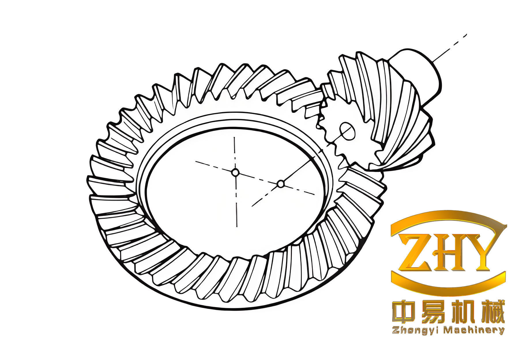
The main advantage of hypoid bevel gears is that their axes are offset. This offset allows the pinion axis to pass below or above the gear axis. As a result, the pinion can be made larger in diameter and stronger than a comparable spiral bevel pinion. The contact ratio is high, the transmission is steady, and the axial installation error is less sensitive than in many other gear types. When the ratio becomes very large, the pinion pitch angle becomes very small. The pinion then behaves partly like a worm and partly like a bevel pinion. This is exactly the region I explore. I have found that with a suitable combination of spiral angle, radial modification, and tangential modification, hypoid bevel gears with four, three, or even two pinion teeth can be designed without tooth profile deterioration.
My design procedure starts from the basic meshing condition of hypoid bevel gears. For a pair of hypoid bevel gears, the two pitch cones are tangent at the pitch point, and the relative velocity at that point is directed along the instantaneous screw axis. The shaft angle is usually \(90^\circ\), but the offset distance \(E\) is not zero. The gear and pinion rotate about crossed axes. The pitch point is not necessarily at the middle of the face width. I introduced a longitudinal position factor \(k_{b2}\) so that the pitch point can be placed at a chosen location along the gear face width. This gives more freedom in the design of few-tooth hypoid bevel gears.
The geometric limits of few-tooth hypoid bevel gears are severe. If the pinion has fewer than five teeth, the classical design charts and programs often cannot be used directly. I therefore established a set of constraints that must be checked for every candidate design. These constraints include undercut, addendum sharpening, tooth surface interference, face cone size, and the direction of the force components. The design must also avoid a cutter interference with the gear face cone. For large ratios, the gear face cone angle can approach \(85^\circ\), so the clearance between the cutter and the gear blank becomes critical.
The first design limitation is undercut. For a pinion with a small pitch angle, the equivalent tooth number is approximately
$$
z_{v1} \approx \frac{z_1}{\cos^3\beta_{m1}}.
$$
Here \(z_1\) is the pinion tooth number and \(\beta_{m1}\) is the pinion middle spiral angle. A larger spiral angle increases the equivalent tooth number and reduces the risk of undercut. In my design examples I used a large spiral angle for the pinion. For a four-tooth pinion I used about \(59^\circ\), and for a three-tooth or two-tooth pinion I used about \(72^\circ\). These values are not arbitrary. They follow from the need to keep the equivalent tooth number above about twenty and to keep the contact path acceptable.
The second limitation is addendum sharpening. The pinion addendum thickness is influenced by both radial and tangential modification. The gear is cut by the Formate method, so the cutter top width controls the pinion addendum thickness. The gear cutter top width \(W_2\) can be written as
$$
W_2 = s_{n1} – 2h_{f2}\tan\alpha_{f1} – 2h_{f2}\tan\alpha_{f2},
$$
where \(s_{n1}\) is the normal circular tooth thickness of the pinion at the pitch point, \(h_{f2}\) is the gear dedendum, and \(\alpha_{f1}\), \(\alpha_{f2}\) are the pressure angles on the two sides. The pinion addendum width \(b_1\) can be estimated from
$$
b_1 = r_{a1}\left[\frac{s_{m1}^*}{r_1} + \mathrm{inv}\,\alpha_{11} – \mathrm{inv}\,\alpha_{12} – \mathrm{inv}\,\alpha_{a1} + \mathrm{inv}\,\alpha_{a2}\right],
$$
where \(r_{a1}\) is the pinion tip radius, \(r_1\) is the pinion pitch radius, and the involute functions refer to the two flanks. I required both \(W_2\) and \(b_1\) to be no less than \(0.4m_n\), where \(m_n\) is the normal module at the middle of the face width. This rule prevented the pinion tip from becoming too sharp.
The third limitation is the minimum tooth space width. If the tooth space at the inner end is too narrow, the cutter cannot enter properly and the cutting force becomes excessive. I used the following estimate:
$$
L_i = W_2 – (h_{f1} + h_{f2})\tan\alpha_{f1} – (h_{f1} + h_{f2})\tan\alpha_{f2} + j_{\min},
$$
where \(j_{\min}\) is the normal backlash and \(h_{f1}\), \(h_{f2}\) are the dedenda. The inner normal pitch \(p_{in}\) is
$$
p_{in} = \frac{2\pi R_i \cos\beta_i}{z_i \sin\delta_i}.
$$
I also required the minimum tooth space width to be at least \(0.4m_n\). This prevented cutter breakage and poor chip removal.
The fourth limitation is the gear face cone angle. When the ratio is large, the gear face cone angle increases. The gear face cone must not interfere with the cutter plane. In my calculations I limited the gear face cone angle to less than \(85^\circ\). This limit becomes the decisive constraint when the ratio is greater than about thirty. For a ratio of thirty, the gear face cone angle can already reach \(84.4^\circ\), so the cutter and the gear blank must be checked very carefully.
The fifth limitation is the force direction. The working flank of hypoid bevel gears should be subjected to a separating force, not a jamming force. I calculated the tangential, axial, and radial forces for both the working side and the coast side. If the axial force is positive, it acts away from the pitch cone apex, which is a separating condition. If it is negative, it acts toward the apex, which may cause jamming. I required the working flank to have positive axial forces for both members. This is an important check for large-ratio hypoid bevel gears because the spiral angle is large and the axial force can change sign easily.
To determine the pitch cone, I first estimate the gear pitch angle. A useful starting approximation is
$$
\tan\delta_2′ = \frac{\sin\Sigma}{\frac{z_1}{z_2} + \cos\Sigma},
$$
where \(\Sigma\) is the shaft angle, \(z_1\) is the pinion tooth number, and \(z_2\) is the gear tooth number. This estimate is then corrected by the offset and the spiral angle. The gear pitch radius at the pitch point is
$$
r_2 = \frac{d_2}{2} – k_{b2}b_2\sin\delta_2,
$$
where \(d_2\) is the gear outer pitch diameter, \(b_2\) is the gear face width, and \(k_{b2}\) is the longitudinal position factor. When \(k_{b2}=0.5\), the pitch point is at the middle of the face width. When \(k_{b2}\) is smaller or larger, the pitch point moves toward the inner or outer end. This is helpful for few-tooth hypoid bevel gears because the strength balance between the pinion and the gear can be adjusted.
The limit pressure angle is another important quantity. I used
$$
\alpha_{\lim} = \arctan\left[\frac{\cos\epsilon}{\sin\Sigma}\left(\frac{\tan\beta_{m1}}{R_{m1}} + \frac{\tan\beta_{m2}}{R_{m2}}\right) – \frac{\tan\delta_1}{R_{m1}} + \frac{\tan\delta_2}{R_{m2}}\right],
$$
where \(\epsilon\) is the offset angle in the axial section, \(\beta_{m1}\) and \(\beta_{m2}\) are the middle spiral angles, and \(R_{m1}\), \(R_{m2}\) are the middle cone distances. The limit curvature radius is
$$
\rho_{\lim} = \frac{\sec^2\beta_{m1}\tan\alpha_{\lim}}{\tan\beta_{m1}\left(\frac{1}{R_{m1}} – \frac{1}{R_{m2}}\right) + \frac{\tan\beta_{m1}}{R_{m1}} + \frac{\tan\beta_{m2}}{R_{m2}}}.
$$
I iterated these equations until the relative change of the limit curvature radius was less than \(0.01\). The final pitch cone parameters were then used to calculate the blank dimensions.
For the gear blank, the outer cone distance is
$$
R_e = \frac{d_2}{2\sin\delta_2}.
$$
The working depth at the middle of the face width is
$$
h = \frac{f r_2 \cos\beta_2}{z_2},
$$
where \(f\) is a coefficient related to the tooth form. The full depth is
$$
h_m = h + c,
$$
and the clearance is
$$
c = 0.15h + 0.05.
$$
The gear addendum and dedendum at the middle are
$$
h_a = \frac{h}{2},\qquad h_f = h – h_a + c.
$$
The gear addendum angle and dedendum angle are
$$
\theta_a = \arctan\frac{h_a}{R_e},\qquad \theta_f = \arctan\frac{h_f}{R_e}.
$$
Therefore the gear face cone angle and root cone angle are
$$
\delta_a = \delta_2 + \theta_a,\qquad \delta_f = \delta_2 – \theta_f.
$$
The gear outer addendum, outer dedendum, and outer full depth are
$$
h_{ae} = h_a + (R_e – R_e)\tan\theta_a,
$$
$$
h_{fe} = h_f + (R_e – R_e)\tan\theta_f,
$$
$$
h_t = h_{ae} + h_{fe}.
$$
In practice these are evaluated at the outer and inner ends. The gear outer diameter is
$$
d_e = d_2 + 2h_{ae}\cos\delta_2.
$$
The distance from the gear crown to the crossing point is
$$
X = Z_G + (R_e – h_{ae}\sin\delta_2) \cos\delta_2.
$$
For the pinion blank, I treated the gear root cone and the pinion face cone as a new pair of pitch cones, and the gear face cone and the pinion root cone as another pair. The pinion middle addendum and dedendum are
$$
h_a’ = h_f – c,\qquad h_f’ = h_a + c.
$$
The pinion face cone angle is obtained from
$$
\sin\delta_{a1} = \frac{\cos\delta_{f2}\sin\Sigma – \sin\delta_{f2}\cos\Sigma}{\cos\epsilon_f}.
$$
The pinion crown distance and inner crown distance follow from the same geometric relations. I used these equations to generate the complete blank dimensions for each candidate design.
The undercut check for the pinion is based on the height modification coefficient. For a check point at cone distance \(R_{x1}\), I computed the corresponding gear cone distance \(R_{x2}\), the spiral angle \(\beta_{x2}\), the offset angle \(\zeta_{xp}\), and the pinion spiral angle \(\beta_{x1}\). The normal module at the check point is
$$
m_x = \frac{d_{x2}\cos\beta_{x2}}{z_2}.
$$
The effective pinion diameter is
$$
d_{Ex1} = d_{x1}\frac{z_2}{z_1}\frac{\cos\beta_{x2}}{\cos\beta_{x1}}.
$$
The limit pressure angle at the check point is
$$
\alpha_{\lim x} = \arctan\left[\frac{\cos\zeta_{mp}}{\sin\Sigma}\left(\frac{\tan\beta_{x1}}{R_{x1}} + \frac{\tan\beta_{x2}}{R_{x2}}\right) – \frac{\tan\delta_1}{R_{x1}} + \frac{\tan\delta_2}{R_{x2}}\right].
$$
The effective pressure angle on the working side is
$$
\alpha_{eDx} = \alpha_{nD} – \alpha_{\lim x},
$$
and on the coast side it is
$$
\alpha_{eCx} = \alpha_{nC} – \alpha_{\lim x}.
$$
I selected the smaller of the two for the minimum height modification coefficient:
$$
x_{hm\min x1} = x_{hx1} + \frac{(d_1 – d_{Ex1})\cos\delta_1}{2m_{mn}}.
$$
If the actual height modification coefficient \(x_{hm1}\) is larger than this minimum, the pinion will not undercut. For my four-to-forty-one example, I used \(R_{x1}=130\), addendum coefficient \(0.05\), and whole depth coefficient \(3.5\). The calculated values were \(x_{hm1}=1.53\) and \(x_{hm\min x1}=0.83\). Since \(1.53>0.83\), the pinion did not undercut. I also checked the gear. The gear is less likely to undercut, but because the height modification is negative, I still checked it. For a check point at \(R_{x2}=35\), the maximum allowable height modification coefficient was \(1.26\). The actual value was \(1.53\), so the gear did not undercut either.
Interference between the fillet and the mating tooth tip is another important check. For cylindrical gears, the condition for no fillet interference can be written as
$$
\tan\alpha_f’ \le \tan\alpha_a – \frac{4(xh_a^* – x)}{z\sin 2\alpha}(\tan\alpha_a – \tan\alpha’).
$$
For hypoid bevel gears I applied this condition separately to the convex and concave flanks, using the normal pressure angle and the equivalent tooth numbers. If the contact start point falls outside the involute start point, the fillet does not participate in meshing. In my examples the interference check was satisfied after radial and tangential modification were included.
The force analysis was performed to ensure that the working flanks always receive a separating force. The gear tangential force is
$$
F_{mt2} = \frac{2000T_2}{d_{m2}},
$$
where \(T_2\) is the gear torque and \(d_{m2}\) is the gear middle pitch diameter. The pinion tangential force is
$$
F_{mt1} = F_{mt2}\frac{\cos\beta_{m2}}{\cos\beta_{m1}}.
$$
For the loaded working side, the pinion axial force is
$$
F_{ax1D} = F_{mt1}\left(\frac{\tan\alpha_{nD}\sin\delta_1}{\cos\beta_{m1}} + \tan\beta_{m1}\cos\delta_1\right),
$$
and the gear axial force is
$$
F_{ax2D} = F_{mt2}\left(\frac{\tan\alpha_{nD}\sin\delta_2}{\cos\beta_{m2}} + \tan\beta_{m2}\cos\delta_2\right).
$$
For the unloaded coast side, the corresponding expressions use the coast-side normal pressure angle \(\alpha_{nC}\). The radial forces are
$$
F_{rad1D} = F_{mt1}\left(\frac{\tan\alpha_{nD}\cos\delta_1}{\cos\beta_{m1}} – \tan\beta_{m1}\sin\delta_1\right),
$$
$$
F_{rad2D} = F_{mt2}\left(\frac{\tan\alpha_{nD}\cos\delta_2}{\cos\beta_{m2}} – \tan\beta_{m2}\sin\delta_2\right).
$$
In my four-to-forty-one example, with a gear torque of \(50\,\mathrm{N\cdot m}\), I obtained the following force values. Positive axial force means the force acts away from the pitch cone apex. Positive radial force means the force acts away from the mating gear.
| Force component | Value | Direction interpretation |
|---|---|---|
| \(F_{ax1D}\) | \(1740.56\,\mathrm{N}\) | Positive, separating |
| \(F_{ax2D}\) | \(814.13\,\mathrm{N}\) | Positive, separating |
| \(F_{ax1C}\) | \(-1576.5\,\mathrm{N}\) | Negative, toward apex |
| \(F_{ax2C}\) | \(598.63\,\mathrm{N}\) | Positive |
| \(F_{rad1D}\) | Positive | Separating |
| \(F_{rad2D}\) | Positive | Separating |
| \(F_{rad1C}\) | Positive | Separating |
| \(F_{rad2C}\) | Negative | Pulling toward mate |
The working side forces were therefore acceptable. This is essential for hypoid bevel gears with a large spiral angle. If the working side axial force were negative, the gear pair could jam under load, and the efficiency would drop sharply.
To understand which geometric parameters most strongly affect the pitch cone angle, I used an orthogonal trial method. The pitch cone angle of the pinion is a good indicator of the design severity. A larger pinion pitch angle increases the equivalent tooth number and the pinion strength. It also reduces the gear face cone angle. I selected four factors: middle spiral angle, cutter diameter, whole depth coefficient, and addendum coefficient. Each factor was assigned three levels.
| Level | Spiral angle \(A\) (deg) | Cutter diameter \(B\) (mm) | Whole depth coefficient \(C\) | Addendum coefficient \(D\) |
|---|---|---|---|---|
| 1 | 56 | 82.9 | 2.5 | -0.1 |
| 2 | 59 | 88.9 | 3.0 | 0.0 |
| 3 | 62 | 94.9 | 3.5 | 0.1 |
Because I did not include interactions in this first orthogonal trial, the four factors occupied four columns. I ran nine trials and computed the pitch cone angle and the middle addendum thickness for each trial.
| Trial | \(A\) | \(B\) | \(C\) | \(D\) | Pitch cone angle | Middle addendum thickness |
|---|---|---|---|---|---|---|
| 1 | 1 | 1 | 1 | 1 | \(7^\circ28’40”\) | 1.911 |
| 2 | 1 | 2 | 2 | 2 | \(6^\circ42’24”\) | 1.526 |
| 3 | 1 | 3 | 3 | 3 | \(6^\circ2’1”\) | 1.177 |
| 4 | 2 | 1 | 2 | 3 | \(7^\circ31’22”\) | 1.719 |
| 5 | 2 | 2 | 3 | 1 | \(6^\circ34’56”\) | 0.978 |
| 6 | 2 | 3 | 1 | 2 | \(5^\circ45’42”\) | 2.027 |
| 7 | 3 | 1 | 3 | 2 | \(7^\circ36’11”\) | 1.269 |
| 8 | 3 | 2 | 1 | 3 | \(6^\circ25’13”\) | 2.098 |
| 9 | 3 | 3 | 2 | 1 | \(5^\circ24’14”\) | 1.564 |
For factor \(A\), the sums at the three levels were \(k_{A1}’=20.218^\circ\), \(k_{A2}’=19.867^\circ\), and \(k_{A3}’=19.427^\circ\). The averages were \(k_{A1}=6.739^\circ\), \(k_{A2}=6.622^\circ\), and \(k_{A3}=6.476^\circ\). Since \(k_{A1}>k_{A2}>k_{A3}\), level \(A1\) gave the largest pitch cone angle. The range was
$$
R_A = 6.739^\circ – 6.476^\circ = 0.264^\circ.
$$
For factor \(B\), the averages were \(k_{B1}=7.535^\circ\), \(k_{B2}=6.57^\circ\), and \(k_{B3}=5.733^\circ\). The range was
$$
R_B = 7.535^\circ – 5.733^\circ = 1.801^\circ.
$$
For factor \(C\), the averages were \(k_{C1}=6.553^\circ\), \(k_{C2}=6.544^\circ\), and \(k_{C3}=6.74^\circ\). The range was
$$
R_C = 6.74^\circ – 6.544^\circ = 0.196^\circ.
$$
For factor \(D\), the averages were \(k_{D1}=6.488^\circ\), \(k_{D2}=6.691^\circ\), and \(k_{D3}=6.659^\circ\). The range was
$$
R_D = 6.691^\circ – 6.488^\circ = 0.203^\circ.
$$
The order of influence was therefore \(B>A>D>C\). The cutter diameter had the strongest effect on the pitch cone angle, followed by the spiral angle, the addendum coefficient, and the whole depth coefficient. This means that for few-tooth hypoid bevel gears, the cutter radius and the spiral angle must be chosen jointly. The best combination in this trial was \(A1B1C3D2\). I used this result as a guide when selecting the final design parameters.
I then completed a full design example with a ratio of \(4:41\). The pinion had four teeth, the gear had forty-one teeth, the offset was \(30\,\mathrm{mm}\), and the shaft angle was \(90^\circ\). I used a middle spiral angle of \(59^\circ\) for the pinion. The main blank parameters are listed below.
| Parameter | Gear | Pinion |
|---|---|---|
| Number of teeth | 41 | 4 |
| Face width | 20 mm | 20 mm |
| Outer addendum | 0.236 mm | — |
| Outer dedendum | 5.247 mm | — |
| Outer full depth | 5.483 mm | 5.647 mm |
| Pitch cone angle | \(81.877^\circ\) | \(6.582^\circ\) |
| Face cone angle | \(82.1^\circ\) | \(10.669^\circ\) |
| Root cone angle | \(76.915^\circ\) | \(6.402^\circ\) |
| Offset distance | 30 mm | — |
| Pitch diameter | 120 mm | — |
| Mean pressure angle | \(22.5^\circ\) | — |
| Shaft angle | \(90^\circ\) | — |
| Middle spiral angle | — | \(59^\circ\) |
| Hand | Right | Left |
The limiting checks for this design are summarized below. I compared the actual values with the limiting or estimated values.
| Check item | Actual value | Limit or estimate |
|---|---|---|
| Pinion middle spiral angle estimate | \(59^\circ\) | \(63.497^\circ\) |
| Gear face cone angle | \(82.1^\circ\) | \(85^\circ\) |
| Equivalent tooth number | 45 | 20 |
| Gear cutter top width | 0.88 mm | 0.8 mm |
| Pinion minimum tooth space width | 2.804 mm | 0.8 mm |
The design passed the undercut, sharpening, interference, and force checks. I then derived the tooth surface equations for both members. The gear is cut by the Formate method. In this method the cutter does not roll relative to the gear blank. The gear tooth surface is therefore a copy of the cutter surface. I established a fixed machine coordinate system, a cutter coordinate system, and a gear coordinate system. For a point on the cutter surface, the position vector is
$$
\mathbf{r}_c =
\begin{bmatrix}
(r_0 – u_g\sin\alpha)\cos\theta_g\\
(r_0 – u_g\sin\alpha)\sin\theta_g\\
-u_g\cos\alpha
\end{bmatrix},
$$
and the unit normal vector is
$$
\mathbf{n}_c =
\begin{bmatrix}
\cos\alpha\cos\theta_g\\
\cos\alpha\sin\theta_g\\
\sin\alpha
\end{bmatrix}.
$$
Here \(r_0\) is the cutter radius, \(u_g\) and \(\theta_g\) are surface parameters, and \(\alpha\) is the cutter profile angle. For the inner cutter, which cuts the gear convex flank, \(\alpha\) is positive. For the outer cutter, which cuts the gear concave flank, \(\alpha\) is negative. The cutter tip radius is
$$
r_0 = \frac{W_2}{2} \pm \frac{W_2}{2},
$$
where the sign depends on the inner or outer cutter. The transformation from the cutter system to the gear system is
$$
\mathbf{r}_2 = \mathbf{M}_{2m}\mathbf{M}_{mG}\mathbf{r}_c + \mathbf{R}_2,
$$
$$
\mathbf{n}_2 = \mathbf{L}_{2m}\mathbf{L}_{mG}\mathbf{n}_c.
$$
The matrix from the cutter system to the machine system is a translation. The matrix from the machine system to the gear system includes the machine root angle \(\gamma_m\) and the axial setting \(x_{g2}\). After expanding the matrix product, the gear tooth surface can be written as
$$
x_2 = \sin\gamma_m\left[H_2 + (r_0 – u_g\sin\alpha)\cos\theta_g\right] + \cos\gamma_m\left[V_2 + (r_0 – u_g\sin\alpha)\sin\theta_g\right] + x_{g2}\cos\gamma_m,
$$
$$
y_2 = V_2 + (r_0 – u_g\sin\alpha)\sin\theta_g,
$$
$$
z_2 = \cos\gamma_m\left[H_2 + (r_0 – u_g\sin\alpha)\cos\theta_g\right] – \sin\gamma_m\left[V_2 + (r_0 – u_g\sin\alpha)\sin\theta_g\right] – x_{g2}\sin\gamma_m.
$$
Here \(H_2\) is the horizontal cutter position, \(V_2\) is the vertical cutter position, and \(x_{g2}\) is the axial gear setting. The gear tooth surface normal in the gear system is
$$
n_{x2} = \sin\gamma_m\cos\alpha\cos\theta_g + \cos\gamma_m\cos\alpha\sin\theta_g,
$$
$$
n_{y2} = \cos\alpha\sin\theta_g,
$$
$$
n_{z2} = \cos\gamma_m\cos\alpha\cos\theta_g – \sin\gamma_m\cos\alpha\sin\theta_g.
$$
The pinion is generated by the gear tooth surface. I established a generating coordinate system in which the gear and pinion rotate about their own axes with the ratio \(i_{12}\). The pinion tooth surface is the envelope of the gear tooth surface. The coordinate transformation from the gear system to the pinion system is
$$
\mathbf{r}_1 = \mathbf{M}_{12}\mathbf{r}_2 + \mathbf{E},
$$
where
$$
\mathbf{M}_{12} = \mathbf{M}_{1’1}\mathbf{M}_{12′}\mathbf{M}_{2’2}.
$$
The matrix \(\mathbf{M}_{2’2}\) rotates the gear by \(\phi_2\), and \(\mathbf{M}_{1’1}\) rotates the pinion by \(\phi_1\). The offset vector is
$$
\mathbf{E} =
\begin{bmatrix}
a\cos\phi_1\\
a\sin\phi_1\\
0
\end{bmatrix}.
$$
The meshing equation during pinion generation is
$$
\mathbf{n}_2\cdot\mathbf{v}_{21}=0,
$$
where \(\mathbf{v}_{21}\) is the relative velocity between the gear and the pinion. I wrote it as
$$
\mathbf{v}_{21} = (\boldsymbol{\omega}_1 – \boldsymbol{\omega}_2)\times\mathbf{r}_2 – \boldsymbol{\omega}_1\times\mathbf{E}.
$$
With \(\omega_1=1\) and \(\omega_2=1/i_{12}\), the expanded relative velocity components are
$$
v_x = -y_2 – \frac{1}{i_{12}} z_2\sin\phi_2,
$$
$$
v_y = x_2 + \frac{1}{i_{12}} z_2\cos\phi_2,
$$
$$
v_z = \frac{1}{i_{12}}(x_2\sin\phi_2 – y_2\cos\phi_2).
$$
Substituting the gear surface position and normal into the meshing equation gives a scalar equation in \(u_g\), \(\theta_g\), and \(\phi_2\). This equation is the generating condition for the pinion. I combined it with the coordinate transformation to eliminate \(\phi_2\) and obtain the pinion tooth surface \(\mathbf{r}_1(u_g,\theta_g)\). The final pinion surface equations are lengthy, but they have the same structure as the gear equations. They include the cutter parameters, the offset, the machine root angle, and the generating ratio. I used these equations in the numerical solution of the tooth surface points.
For the three-dimensional simulation, I first divided the tooth surface into a grid on the rotation projection plane. The projection plane uses the coordinates
$$
X = x,
$$
$$
Y^2 = y^2 + z^2.
$$
I divided the tooth surface into five points in the tooth height direction and nine points in the tooth length direction. This gave forty-five grid points. The four boundary vertices were computed from the blank geometry. For example, the outer addendum vertex is
$$
X_2 = R_e\cos\delta_a – h_{ae}\sin\delta_a,
$$
$$
Y_2 = R_e\sin\delta_a + h_{ae}\cos\delta_a.
$$
The inner dedendum vertex is
$$
X_3 = R_i\cos\delta_f + h_{fe}\sin\delta_f,
$$
$$
Y_3 = R_i\sin\delta_f – h_{fe}\cos\delta_f.
$$
The other two vertices were obtained by moving along the face width. The boundary points were then linearly interpolated, and the interior points were found from the intersection of two families of lines. For any interior grid point \((X_{ij},Y_{ij})\), I solved
$$
X_{ij} = \frac{Y_{ij} – S X_{i1} + Q X_{1j} – Y_{1j}}{Q – S},
$$
$$
Y_{ij} = Y_{i1} + S(X_{ij} – X_{i1}),
$$
where
$$
S = \frac{Y_{15}-Y_{11}}{X_{15}-X_{11}},\qquad Q = \frac{Y_{i9}-Y_{i1}}{X_{i9}-X_{i1}}.
$$
Once the projection grid was known, I solved the nonlinear tooth surface equations for the three-dimensional coordinates. I used MATLAB for this step. The gear and pinion surface points were written into a data file and imported into a three-dimensional CAD environment. I created the tooth surface patches by lofting the point grids, added the root surface, trimmed the blank, and patterned the tooth space around the axis. The resulting models allowed me to inspect undercut, sharpening, and tooth profile distortion directly.
I built models for ratios of \(4:41\), \(3:60\), and \(2:60\). The four-tooth pinion had a middle spiral angle of \(59^\circ\). The three-tooth and two-tooth pinions used a middle spiral angle of \(72^\circ\). The main parameters of the three-to-sixty design are listed below.
| Parameter | Gear | Pinion |
|---|---|---|
| Number of teeth | 60 | 3 |
| Face width | 20 mm | 20 mm |
| Outer addendum | 0.143 mm | — |
| Outer dedendum | 3.194 mm | — |
| Outer full depth | 3.337 mm | 3.391 mm |
| Pitch cone angle | \(84.005^\circ\) | \(5.666^\circ\) |
| Face cone angle | \(84.176^\circ\) | \(7.386^\circ\) |
| Root cone angle | \(81.25^\circ\) | \(4.91^\circ\) |
| Offset distance | 30 mm | — |
| Pitch diameter | 130 mm | — |
| Mean pressure angle | \(22.5^\circ\) | — |
| Shaft angle | \(90^\circ\) | — |
| Middle spiral angle | — | \(72^\circ\) |
| Hand | Right | Left |
| Check item | Actual value | Limit or estimate |
|---|---|---|
| Pinion middle spiral angle estimate | \(72^\circ\) | \(68.13^\circ\) |
| Gear face cone angle | \(84.176^\circ\) | \(85^\circ\) |
| Equivalent tooth number | 102 | 20 |
| Gear cutter top width | 1.2 mm | 0.8 mm |
| Pinion minimum tooth space width | 2.239 mm | 0.8 mm |
The three-tooth pinion model showed a continuous root and a proper tip thickness. There was no undercut and no sharpening. The gear also had a sound tooth profile. The face cone angle was close to the limit, but it remained below \(85^\circ\). I then increased the ratio to \(2:60\). The main parameters are listed below.
| Parameter | Gear | Pinion |
|---|---|---|
| Number of teeth | 60 | 2 |
| Face width | 20 mm | 20 mm |
| Outer addendum | 0.147 mm | — |
| Outer dedendum | 3.293 mm | — |
| Outer full depth | 3.440 mm | 3.492 mm |
| Pitch cone angle | \(84.311^\circ\) | \(4.938^\circ\) |
| Face cone angle | \(84.431^\circ\) | \(7.273^\circ\) |
| Root cone angle | \(81.629^\circ\) | \(4.835^\circ\) |
| Offset distance | 30 mm | — |
| Pitch diameter | 140 mm | — |
| Mean pressure angle | \(22.5^\circ\) | — |
| Shaft angle | \(90^\circ\) | — |
| Middle spiral angle | — | \(72^\circ\) |
| Hand | Right | Left |
| Check item | Actual value | Limit or estimate |
|---|---|---|
| Pinion middle spiral angle estimate | \(72^\circ\) | \(71.672^\circ\) |
| Gear face cone angle | \(84.431^\circ\) | \(85^\circ\) |
| Equivalent tooth number | 68 | 20 |
| Gear cutter top width | 1.8 mm | 0.8 mm |
| Pinion minimum tooth space width | 1.962 mm | 0.8 mm |
The two-tooth pinion also had a continuous root and a sound tip. There was no undercut and no sharpening. The gear face cone angle reached \(84.431^\circ\), which is very close to the \(85^\circ\) limit. This means that for ratios above thirty, the gear face cone and the cutter interference become the primary design concerns. The pinion tooth number can be reduced further in principle, but the cutter clearance and the blank stiffness must be checked carefully. In my models, however, the two-tooth hypoid bevel gears were geometrically feasible.
After the three-dimensional simulation, I calculated the machine settings for a \(4:41\) pair and performed a tooth contact analysis. The gear was cut by the Formate method, and the pinion was cut by the tilt method. The gear machine settings are listed below.
| Parameter | Value |
|---|---|
| Blank mounting angle | \(76.915^\circ\) |
| Vertical cutter position | 49.084 mm |
| Horizontal cutter position | 26.094 mm |
| Axial setting correction | 44.21 mm |
| Cradle angle | \(96.242^\circ\) |
| Eccentric angle | \(43.504^\circ\) |
The pinion machine settings are listed below. The convex and concave flanks were cut separately, so two sets of parameters are given.
| Parameter | Convex flank | Concave flank |
|---|---|---|
| Blank mounting angle | \(-3.314^\circ\) | \(-3.456^\circ\) |
| Radial cutter position | 54.161 mm | 55.708 mm |
| Angular cutter position | \(91.204^\circ\) | \(83.209^\circ\) |
| Axial setting correction | -0.324 mm | 0.536 mm |
| Work head setting | 0.077 mm | -0.685 mm |
| Vertical offset | 27.346 mm | 32.046 mm |
| Roll ratio | 9.732 | 10.299 |
| Basic cutter rotation | \(-36.718^\circ\) | \(-46.073^\circ\) |
| Basic cutter tilt | \(11.941^\circ\) | \(0.129^\circ\) |
| Machine cutter rotation | \(8.82^\circ\) | \(357.753^\circ\) |
| Machine cutter tilt | \(47.392^\circ\) | \(48.183^\circ\) |
| Eccentric angle | \(42.333^\circ\) | \(43.602^\circ\) |
| Cradle angle | \(194.67^\circ\) | \(196.29^\circ\) |
I used these settings in a tooth contact analysis program. The contact pattern had a small internal diagonal, and the transmission error curve was nearly symmetric. This indicated that the machine settings were accurate enough for a cutting trial. The contact path was not concentrated at the tooth edges, and the contact ellipse stayed within the tooth surface. The maximum transmission error was small, which is beneficial for smooth operation of hypoid bevel gears.
The cutting experiment was performed on a spiral bevel gear milling machine. The machine was a cradle-type milling machine with a three-axis numerical control system. The original change gears were replaced by servo drives, which improved the indexing accuracy and made the setup more flexible. I used a double-sided finish cutter for both the gear and the pinion. The cutter had one reference inner blade and one reference outer blade. The remaining blades were adjusted with shims so that all blades of the same name had the same diameter. This is important for maintaining a uniform tooth thickness in hypoid bevel gears.
For the gear, the main cutting risk was interference between the cutter and the gear face cone. Because the gear face cone angle was close to \(85^\circ\), I checked the extreme positions of the machine, the cutter, and the blank before cutting. The gear was cut by the Formate method. I adjusted the cutter diameters, set the blank mounting angle, entered the cradle angle and eccentric angle, and fed the cutter to the full depth. After the first cut, I measured the chordal tooth height and chordal tooth thickness. These measurements were used to set the final feed. The gear cutting was completed without interference.
For the pinion, the main risks were undercut, tip sharpening, and machine interference. The pinion had only four teeth, which is below the usual limit of five. I designed special fixtures and a locating sleeve to mount the pinion blank on the machine. These fixtures avoided interference among the cutter, the cradle, the machine bed, and the work head. I set the pinion mounting angle, horizontal setting, eccentric angle, and vertical offset. For the concave flank, I cut to the full depth in one pass. For the convex flank, I corrected the tooth thickness by adjusting the machine \(Y\)-axis feed. The pinion was completed without undercut and without a sharp tip.
The finished gear and pinion were placed together for inspection. The actual tooth shapes agreed with the three-dimensional models. The gear had a smooth root and a sound face cone. The pinion had four well-formed teeth with continuous roots and proper tip thickness. The tooth contact pattern was close to the predicted pattern from the tooth contact analysis. This confirmed that my geometric design, tooth surface equations, and machine settings were consistent with the real cutting process. The experiment also confirmed that hypoid bevel gears with four pinion teeth and a ratio of \(4:41\) can be manufactured by the Formate and tilt methods.
From this work I draw several conclusions. First, few-tooth hypoid bevel gears with ratios of ten to thirty can be designed successfully if radial and tangential modifications are used together. The pinion spiral angle must be large enough to avoid undercut and tip sharpening. The gear face cone angle must be kept below \(85^\circ\) to avoid cutter interference. Second, the tooth surface equations of the gear and pinion can be derived from the Formate cutting geometry and the generating enveloping principle. The gear surface is a direct copy of the cutter surface, while the pinion surface is the envelope of the gear surface. Third, the three-dimensional simulation is a powerful tool for evaluating few-tooth hypoid bevel gears. It allows undercut, sharpening, and tooth profile distortion to be inspected before cutting. Fourth, the cutting experiment verified that a \(4:41\) hypoid bevel gear pair can be produced with the calculated machine settings. The actual tooth shapes matched the theoretical models.
There are still many areas to explore. I limited the ratio to about thirty in my study. A ratio larger than thirty, with a pinion tooth number of one, may be possible, but it requires further study of the face cone limit, cutter interference, and blank stiffness. The orthogonal trial I used did not include interactions among the geometric parameters. Future work should include a full factorial or optimization study of the spiral angle, cutter diameter, pressure angle, whole depth coefficient, and modification coefficients. The three-dimensional models I built did not include the fillet and tip transition surfaces in full detail. More accurate modeling of the root fillet and tip chamfer would improve the prediction of stress concentration and contact behavior. Finally, more cutting experiments and loaded contact tests are needed for three-tooth and two-tooth hypoid bevel gears. These tests will provide the data needed for industrial application of few-tooth, high-ratio hypoid bevel gears.
In summary, my study shows that few-tooth hypoid bevel gears are a promising solution for compact, high-ratio, high-efficiency transmissions. They combine the smoothness and load capacity of hypoid bevel gears with the large single-stage ratio of worm gearing. With careful geometric design, accurate tooth surface equations, three-dimensional verification, and proper machine settings, hypoid bevel gears with four, three, or even two pinion teeth can be designed and manufactured. I believe this work provides a useful foundation for further research and application of few-tooth, large-ratio hypoid bevel gears.