
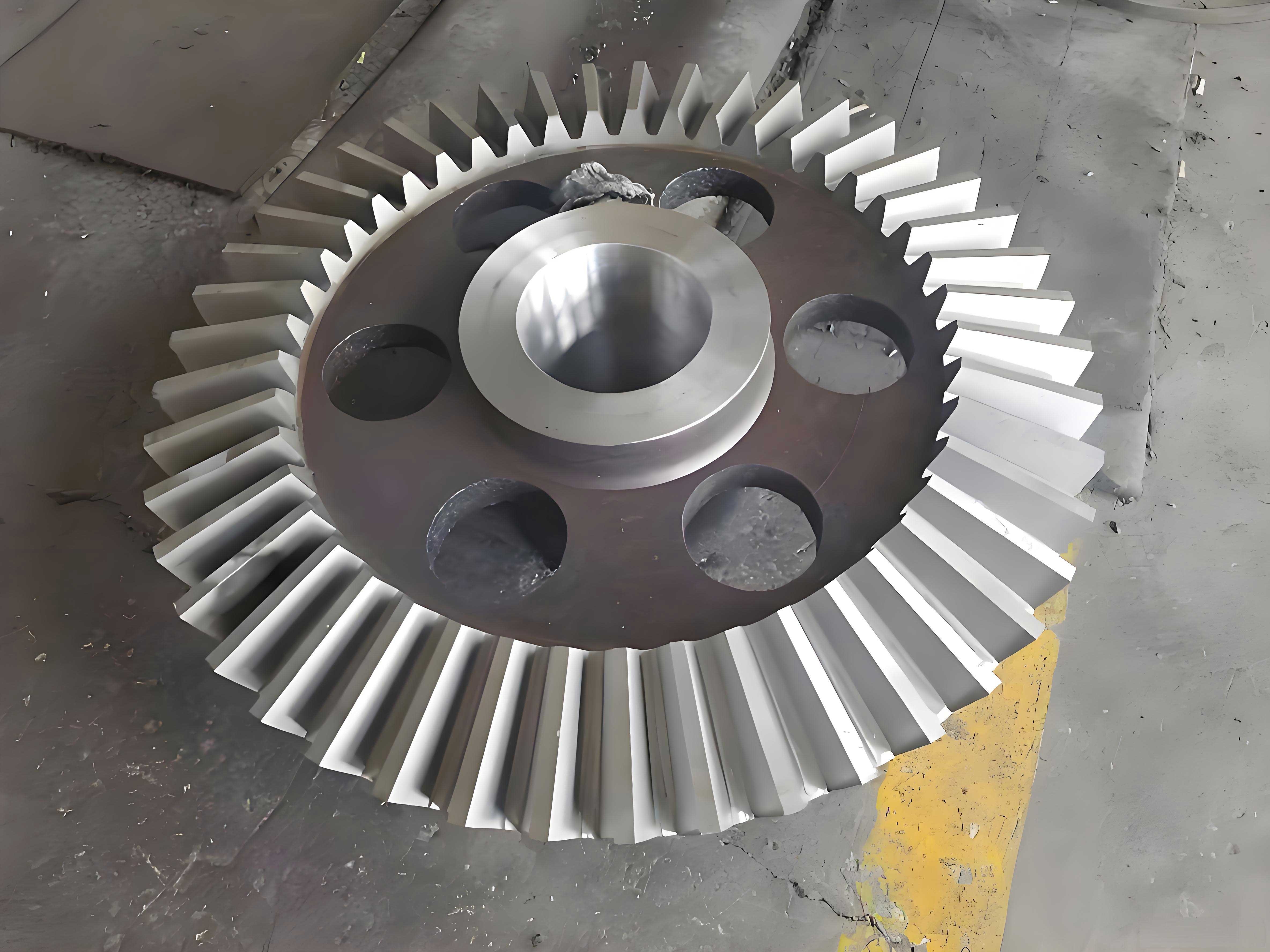
In my research, I focus on the meshing behavior of a miter gear, which is a double-helical gear composed of two symmetric helical gear sections separated by a central relief groove. The miter gear offers high load capacity, smooth operation, and self-cancellation of axial forces, making it widely applicable in high-speed, heavy-duty, and high-power transmission systems. However, because the left and right helical sections of a miter gear are machined separately, unavoidable manufacturing errors prevent perfect symmetry between the two tooth flanks. This asymmetry gives rise to a unique characteristic called symmetry error, which strongly affects vibration, noise, and load-sharing uniformity. In this work, I define symmetry error according to form errors, develop a tooth contact analysis (TCA) model and a loaded tooth contact analysis (LTCA) model for a miter gear pair with symmetry error, and verify the models through finite element simulations and experiments. The main goal is to reveal how symmetry error influences the meshing characteristics of a miter gear and to propose an effective error compensation method.
The miter gear studied here is an aviation power miter gear. I treat the left and right helical gear sections as two separate helical gear pairs. The symmetry error is defined as the distance from the actual intersection point of the left and right helices on the pitch cylinder to the theoretical central plane. This error is a key parameter that determines the initial gap between the left and right tooth flanks. When the symmetry error is present, the load distribution between the left and right sections becomes uneven, leading to biased contact and reduced transmission stability. Therefore, I systematically investigate the influence of symmetry error on the miter gear meshing performance.
To establish the theoretical foundation, I first derive the tooth surface equations for a helical gear based on the gear meshing principle. The helical gear tooth surface is generated by a rack cutter. The rack cutter profile is shown in my derivation, where the parabolic modification is introduced to convert line contact into point contact. The position vector and unit normal vector of the rack cutter are expressed as follows:
$$ \mathbf{r}_{ai} = [u_i, a_i u_i^2, l_i]^T $$
$$ \mathbf{n}_{ai} = \frac{\frac{\partial \mathbf{r}_{ai}}{\partial u_i} \times \frac{\partial \mathbf{r}_{ai}}{\partial l_i}}{\left| \frac{\partial \mathbf{r}_{ai}}{\partial u_i} \times \frac{\partial \mathbf{r}_{ai}}{\partial l_i} \right|} = \frac{[-2a_i u_i, 1, 0]^T}{\sqrt{1 + 4a_i^2 u_i^2}} $$
Here, \(u_i\) and \(l_i\) are the surface parameters of the cutter, and \(a_i\) is the parabolic modification coefficient. By applying coordinate transformations, I obtain the position vector and normal vector of the cutter in the coordinate system \(S_{ti}\):
$$ \mathbf{r}_{ti} = \mathbf{M}_{tn} \mathbf{M}_{na} \mathbf{r}_{ai} $$
$$ \mathbf{n}_{ti} = \mathbf{L}_{tn} \mathbf{L}_{na} \mathbf{n}_{ai} $$
The transformation matrices \(\mathbf{M}_{tn}\) and \(\mathbf{M}_{na}\) involve the normal pressure angle \(\alpha\) and the helix angle \(\beta_i\). The meshing equation between the rack cutter and the gear blank is given by:
$$ f_i(u_i, l_i, \theta_i) = \mathbf{n}_{ti} \cdot \mathbf{V}_{ti}^{(i)} = 0 $$
where \(\mathbf{V}_{ti}^{(i)}\) is the relative velocity between the cutter and the gear. Solving this equation yields the relation for the gear tooth surface. The final tooth surface position and normal vectors are:
$$ \mathbf{r}_i(u_i, \theta_i) = \mathbf{M}_{it} \mathbf{r}_{ti} $$
$$ \mathbf{n}_i(u_i, \theta_i) = \mathbf{L}_{it} \mathbf{n}_{ti} $$
With these equations, I can describe the helical gear tooth surface precisely. For a miter gear, I combine two helical gear pairs: one left pair and one right pair. The TCA model for a standard miter gear pair is established by solving the contact equations for each helical pair and then assembling the results. The contact equations for the left and right pairs are:
$$ \mathbf{r}_f^{(1)}(u_1, \theta_1, \phi_1) = \mathbf{r}_f^{(2)}(u_2, \theta_2, \phi_2) $$
$$ \mathbf{n}_f^{(1)}(u_1, \theta_1, \phi_1) = \mathbf{n}_f^{(2)}(u_2, \theta_2, \phi_2) $$
Since the normal vectors are unit vectors, these equations provide five independent scalar equations. With the input rotation angle \(\phi_1\) given, the remaining five unknowns can be solved. By varying \(\phi_1\) step by step, I obtain the contact path and the geometric transmission error. The geometric transmission error is defined as:
$$ \delta\phi_2 = \left( \phi_2 – \phi_2^{(0)} \right) – \frac{Z_1}{Z_2} \left( \phi_1 – \phi_1^{(0)} \right) $$
For a miter gear pair, the left and right sections may have a phase difference due to manufacturing errors. I introduce a relative phase angle \(\Delta\phi = \Xi_e / (r_b \cos\beta_b)\), where \(\Xi_e\) is the relative machining error, \(r_b\) is the base radius, and \(\beta_b\) is the base helix angle. Thus, the left and right pinion rotation angles are related by \(\phi_{1L} = \phi_{1R} – \Delta\phi\). The geometric transmission errors for the left and right sections are computed separately and then combined.
Next, I establish the LTCA model. The loaded tooth contact analysis considers the displacement compatibility, force equilibrium, and non-embedding contact conditions. The initial tooth surface gap consists of the inter-tooth gap and the normal gap. The inter-tooth gap is determined by the geometric transmission error, while the normal gap is computed along the instantaneous contact ellipse. For a point \(q\) on the contact ellipse, the normal gap \(b_q\) is the distance between the two tooth surfaces along the common normal. The flexibility matrix of the gear pair is obtained by finite element interpolation. The displacement compatibility equation after loading is:
$$ \mathbf{F}_k \mathbf{P}_k + \mathbf{w}_k = \mathbf{Z}_k + \mathbf{d}_k, \quad k = \mathrm{I}, \mathrm{II}, \mathrm{III}, \mathrm{IV} $$
where \(\mathbf{F}_k\) is the normal flexibility matrix, \(\mathbf{P}_k\) is the normal load vector, \(\mathbf{w}_k\) is the initial gap vector, \(\mathbf{Z}_k\) is the normal displacement vector, and \(\mathbf{d}_k\) is the residual gap vector. The force equilibrium condition for a miter gear pair is:
$$ \sum_{j=1}^{n} p_j^{\mathrm{I}} + \sum_{j=1}^{n} p_j^{\mathrm{II}} + \sum_{j=1}^{n} p_j^{\mathrm{III}} + \sum_{j=1}^{n} p_j^{\mathrm{IV}} = P_L + P_R = P $$
The non-embedding contact condition is:
$$ \text{if } p_{jk} > 0, \text{ then } d_{jk} = 0; \quad \text{if } p_{jk} = 0, \text{ then } d_{jk} > 0 $$
Using mathematical programming, I solve these equations to obtain the loaded transmission error, the load distribution along the contact ellipse, and the residual gaps. The meshing stiffness is then calculated from the instantaneous total normal force \(p\) and the total deformation \(\delta\):
$$ k = \frac{p}{\delta} $$
For a miter gear pair, the left and right meshing stiffnesses are:
$$ k_L = \frac{T}{r_{b2} \cos\alpha_n \cos\beta \left( Z_L – TE_L \right)}, \quad k_R = \frac{T}{r_{b2} \cos\alpha_n \cos\beta \left( Z_R – TE_R \right)} $$
Now I define the symmetry error of a miter gear. The symmetry error \(\Delta T\) is the distance from the actual intersection point \(H\) of the left and right helices to the central plane. Projecting this error onto the center line and converting to radians gives:
$$ a = \frac{\Delta T \tan\beta}{r} $$
To model the symmetry error, I rotate the right pinion tooth surface by an angle \(a\) around its axis. The transformed position and normal vectors are:
$$ \mathbf{r}_1′ = \mathbf{M} \mathbf{r}_1, \quad \mathbf{n}_1′ = \mathbf{L} \mathbf{n}_1 $$
where \(\mathbf{M}\) is the rotation matrix:
$$ \mathbf{M} = \begin{bmatrix} \cos a & \sin a & 0 & 0 \\ -\sin a & \cos a & 0 & 0 \\ 0 & 0 & 1 & 0 \\ 0 & 0 & 0 & 1 \end{bmatrix} $$
With this modification, the TCA and LTCA models for a miter gear pair with symmetry error are established. The initial gap vector for the right section becomes \(\mathbf{w}_k = \mathbf{b}_k + \boldsymbol{\delta}_k + \Delta T \tan\beta\), while for the left section it is \(\mathbf{w}_k = \mathbf{b}_k + \boldsymbol{\delta}_k – \Delta T \tan\beta\). The force equilibrium and non-embedding conditions remain the same, but the load distribution \(P_L\) and \(P_R\) are no longer equal.
To verify my models, I built a three-dimensional finite element model of a miter gear pair with symmetry error. The basic parameters of the gear pair are listed in Table 1. I used a commercial software to create the involute tooth profile and the helical gear solid model. The finite element mesh was refined in the contact region. The contact and boundary conditions were set with a torque of 2000 N·m on the pinion and a fixed large gear. The finite element results were compared with my LTCA results.
| Parameter | Large gear | Pinion |
|---|---|---|
| Number of teeth \(z\) | 81 | 27 |
| Normal module \(m_n\) (mm) | 3.5 | 3.5 |
| Normal pressure angle \(\alpha_n\) (deg) | 20 | 20 |
| Helix angle \(\beta\) (deg) | 30 | 30 |
| Face width \(b\) (mm) | 30×2 | 30×2 |
| Relief groove length \(H\) (mm) | 55 | 55 |
| Symmetry error \(\Delta T\) (mm) | 0.01 | 0.01 |
For the contact pattern comparison, the TCA method and the finite element method gave similar results. The contact pattern became longer and then shorter during the meshing cycle. Due to symmetry error, the contact points on the left and right flanks shifted slightly, but the overall contact remained good. The loaded transmission errors for the left and right flanks are shown in Table 2. The LTCA method gave slightly smaller mean values and fluctuation amplitudes than the finite element method, with mean errors of 3.12% for the left flank and 5.21% for the right flank. This validates the correctness of my LTCA model.
| Method | Left mean (arcsec) | Left amplitude (arcsec) | Right mean (arcsec) | Right amplitude (arcsec) |
|---|---|---|---|---|
| Finite element | -4.9554 | 10.711 | -4.1588 | 9.332 |
| LTCA | -4.8008 | 8.659 | -3.9423 | 7.537 |
The meshing stiffness comparison is shown in Table 3. Again, the LTCA results were slightly lower than the finite element results, with mean errors of 2.48% for the left flank and 3.46% for the right flank. These comparisons confirm the accuracy of my proposed method for miter gear analysis with symmetry error.
| Method | Left mean (N/m) | Left amplitude (N/m) | Right mean (N/m) | Right amplitude (N/m) |
|---|---|---|---|---|
| Finite element | 6.529×10^8 | 1.260×10^8 | 5.334×10^8 | 1.207×10^8 |
| LTCA | 6.367×10^8 | 1.233×10^8 | 5.149×10^8 | 1.191×10^8 |
After validating the models, I investigated the influence of symmetry error on the miter gear meshing characteristics. I considered four cases: \(\Delta T = 0\), 0.01, 0.02, and 0.03 mm. For each case, I performed TCA and LTCA under a fixed pinion condition. The contact point coordinates for the left and right flanks are summarized in Table 4 for \(\Delta T = 0.01\) mm. As the symmetry error increases, the right flank contact points move toward the tooth root, while the left flank remains unchanged. The geometric transmission error on the right side increases with symmetry error. For example, at \(\Delta T = 0.01\) mm, the right geometric transmission error is from -8.062 to -7.275 arcsec; at \(\Delta T = 0.02\) mm, it is from -15.337 to -14.551 arcsec; at \(\Delta T = 0.03\) mm, it is from -22.614 to -21.827 arcsec. This increasing transmission error causes impact and vibration during operation.
| Left X (mm) | Left Y (mm) | Right X (mm) | Right Y (mm) |
|---|---|---|---|
| -15.000000 | 6.333924 | — | — |
| -15.000000 | 5.740138 | 15.000000 | 5.740386 |
| -15.000000 | 5.049065 | 15.000000 | 5.049397 |
| -15.000000 | 4.264508 | 15.000000 | 4.264934 |
| -14.472214 | 3.500000 | 14.482214 | 3.500000 |
| -10.073984 | 3.500000 | 10.083984 | 3.500000 |
| -5.675754 | 3.500000 | 5.685754 | 3.500000 |
| -1.277525 | 3.500000 | 1.287525 | 3.500000 |
| 3.120705 | 3.500000 | -3.110705 | 3.500000 |
| 7.518935 | 3.500000 | -7.508935 | 3.500000 |
| 11.917164 | 3.500000 | -11.907164 | 3.500000 |
| 15.000000 | 3.224925 | -15.000000 | 3.225473 |
| 15.000000 | 2.251030 | -15.000000 | 2.251690 |
| 15.000000 | 1.197154 | -15.000000 | 1.197933 |
| 15.000000 | 0.067706 | -15.000000 | 0.068611 |
The load distribution results show that when \(\Delta T = 0\), the load is equally shared between the left and right flanks. As \(\Delta T\) increases, the left flank carries more load and the right flank carries less. At \(\Delta T = 0.03\) mm, the load is mostly concentrated on the left side, indicating severe biased contact. The loaded transmission error curves also change: the left loaded transmission error increases with symmetry error, while the right loaded transmission error decreases. The meshing stiffness of both sides decreases as symmetry error increases, with the right side showing a more pronounced reduction. These results clearly demonstrate that symmetry error degrades the miter gear meshing stability.
I also studied the case where the pinion is axially floating. In this condition, the pinion can move along its axis to balance the axial forces. Under a symmetry error of 0.01 mm, the contact pattern of the floating pinion is uniform, and the load distribution becomes nearly equal on both sides. The inter-tooth load distribution coefficients are close to each other, meaning that the floating pinion can achieve load sharing between the left and right gear pairs. However, the tooth surface load on each individual tooth still exhibits some bias. The axial displacement of the pinion is periodic and increases with symmetry error. For \(\Delta T = 0.01\), 0.02, and 0.03 mm, the axial displacement amplitudes are approximately 5, 10, and 15 μm, respectively.
To further improve the load distribution, I proposed a tooth flank modification method. The modification includes both profile and lead modifications. The profile modification is applied to the pinion root to avoid edge contact. The lead modification is applied along the tooth width. For a standard miter gear without symmetry error and without axial floating, the modification reduces the loaded transmission error amplitude by 32.77% and the meshing stiffness amplitude by 10.36%. The mean values also decrease. However, when symmetry error exists, a uniform modification is not sufficient. Therefore, I developed an error compensation method based on lead compensation modification. The principle is to apply a larger modification amount where the initial gap is smaller and a smaller modification amount where the initial gap is larger. This compensates for the symmetry error and equalizes the load distribution.
For a miter gear with \(\Delta T = 0.01\) mm, after error compensation, the contact pattern and geometric transmission error become uniform on both sides. The load distribution is almost equal on the left and right flanks, similar to the ideal case. The loaded transmission error amplitudes for the left and right flanks become equal at 6.28 arcsec. Compared with the uncompensated case, the left amplitude decreases by 27.47%, while the right amplitude increases by 4.03%. The meshing stiffness also becomes equal on both sides, with amplitudes of \(1.168 \times 10^8\) N/m. The left amplitude decreases by 5.27%, and the right amplitude decreases by 1.95%. This error compensation method effectively achieves uniform loading and improves the miter gear meshing performance.
Finally, I conducted experimental verification. I designed and machined a pair of miter gears according to an aviation power transmission requirement. The symmetry error was measured using a CNC gear measuring center with the full-tooth helix method. The measured symmetry error was about 0.010 mm. I built a miter gear transmission system test rig. The test rig included a drive motor, a load motor, torque sensors, and a control system. I tested the contact pattern under low-speed quasi-static conditions with two support configurations: axially fixed pinion and axially floating pinion. The contact pattern results showed that when the pinion was axially fixed, the left and right contact patterns were not symmetric and were unevenly distributed. When the pinion was axially floating, the contact patterns became basically symmetric. These experimental results agree with my simulation results and validate the correctness of my theoretical models.
I also measured the axial displacement of the pinion under the floating condition. The experimental results showed a periodic axial displacement with a sudden increase at the beginning of meshing due to symmetry error. The trend of the experimental curve matched the simulation curve well, although the experimental values were slightly larger due to machining errors and environmental factors. This further confirms the accuracy of my simulation method.
In summary, my research provides a comprehensive analysis of miter gear meshing with symmetry error. I established TCA and LTCA models, defined and modeled symmetry error, verified the models with finite element analysis, investigated the influence of symmetry error on load distribution, transmission error, and meshing stiffness, proposed an error compensation method, and validated the findings through experiments. The main conclusions are as follows: symmetry error causes uneven contact patterns and load distribution, increases geometric transmission error, and reduces meshing stiffness. Axial floating of the pinion can achieve load sharing between left and right gear pairs but cannot eliminate tooth surface bias. Lead compensation modification can effectively compensate for symmetry error and achieve uniform loading. Experimental results confirm the feasibility and accuracy of the proposed methods. This work provides a theoretical basis for the design, manufacturing, and measurement of miter gears with symmetry error.
| Symmetry error \(\Delta T\) (mm) | Right geometric TE range (arcsec) | Left load share (%) | Right load share (%) |
|---|---|---|---|
| 0 | 0 | 50 | 50 |
| 0.01 | -8.062 to -7.275 | ~55 | ~45 |
| 0.02 | -15.337 to -14.551 | ~60 | ~40 |
| 0.03 | -22.614 to -21.827 | ~65 | ~35 |
For future work, I plan to consider the variation of symmetry error among individual teeth, because in actual machining the error between adjacent teeth is not constant. I also intend to explore new measurement methods to obtain more accurate symmetry error values. The miter gear remains a key component in high-performance transmission systems, and my research contributes to improving its reliability and stability.