
I have worked on the manufacturing chain for drive beveloid gears for many years, and I have learned that the threaded end is one of the most deceptive features in the entire component. It appears simple, yet it carries high tensile loads, alternating stresses, assembly torque, and the concentrated consequences of every upstream gear cutting, heat treatment, and finishing decision. In my experience, a gear cutting process can produce a geometrically excellent tooth flank and still leave a threaded end that fractures, jams, or releases its nut in service. My objective in this work was therefore not limited to one operation. I treated the threaded end as a system, traced the failure path from gear cutting through heat treatment and assembly, and then rebuilt the process around measurable hardness distribution, controlled stress concentration, and verified appearance quality.
The failures I investigated were not isolated. I saw thread-end fractures, thread jamming during nut engagement, and nut detachment after field use. Each symptom pointed to a different immediate cause, but all of them shared a common theme: the threaded end had been allowed to inherit a stress state and hardness state that the original drawing did not intend. The gear cutting process created the blank geometry, the thread rolling or turning operation created the thread profile, and the heat treatment operation created the final mechanical properties. When these steps were not linked by a single control plan, the threaded end became a weak link. I therefore organized the investigation around three questions. First, what did the failed parts actually show in hardness, microstructure, fracture surface, and appearance? Second, which process variables allowed those conditions to form? Third, what changes in gear cutting, threading, protection, heat treatment, and inspection would make the result robust rather than merely acceptable?
I began by reviewing the technical requirements for the threaded end. The requirements were strict because the thread is a fatigue-critical feature. Any microcrack, carbon enrichment, hardness spike, burr, or geometric discontinuity can become a crack initiation site. Table 1 summarizes the requirements I used as the baseline for acceptance.
| Requirement Area | Specification | Reason for Control |
|---|---|---|
| Microcracks | No microcracks at thread, thread run-out, or radius | Thread roots and radius transitions are stress concentration zones. |
| Thread hardness | 288-596 HV0.3 or 30-55 HRC | Balance strength, wear resistance, and toughness. |
| Hardness inspection face | Defined face and location | Ensure measurement repeatability. |
| Roughness | Controlled at defined surfaces | Reduce friction, galling, and crack initiation. |
| Visual defects | No visible impact damage, burr, or broken tooth | Maintain thread engagement and sealing. |
The production route I examined was straightforward on paper: machine the diameter 35 mm cylindrical surface, perform gear cutting and pre-heat thread machining, apply an anti-carburizing agent to the thread, carburize, quench, temper, clean the anti-carburizing agent, chase the thread, and finish the part. Table 2 shows the original route in more detail. The route itself was not unusual. The problem was that several steps had hidden interactions. For example, the anti-carburizing agent could dry and crack, the transition zone could receive more carbon than intended, and the thread end could be damaged during handling between gear cutting and final assembly.
| Step | Operation | Key Parameter or Condition | Purpose |
|---|---|---|---|
| 1 | Machine cylindrical surface | Diameter 35 mm | Create locating and sealing surface. |
| 2 | Pre-heat thread machining and gear cutting | Thread profile and tooth geometry | Establish pre-heat geometry for later processing. |
| 3 | Apply anti-carburizing agent | Thread area coating | Prevent excessive carbon and hardness in thread. |
| 4 | Carburize, quench, temper | Case-hardening cycle | Develop core and case properties. |
| 5 | Clean anti-carburizing agent | Post-heat-treatment cleaning | Remove coating residue. |
| 6 | Chase thread | Thread finishing | Correct distortion and restore fit. |
| 7 | Final inspection and finish | Dimensional and visual checks | Release conforming product. |
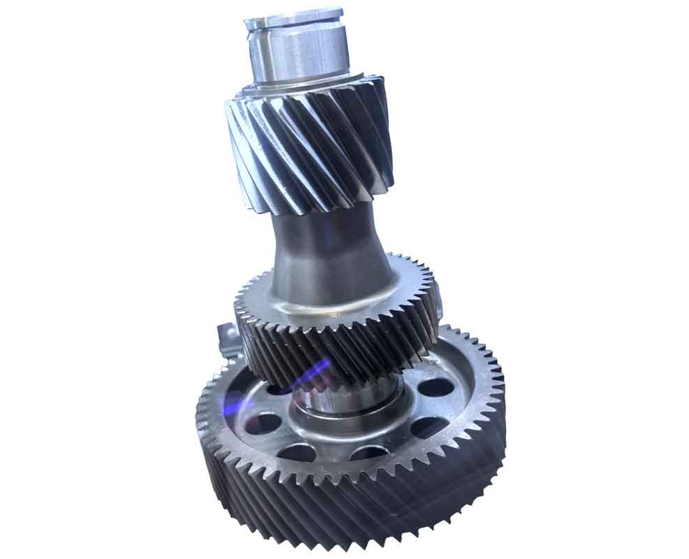
When I examined the failed threaded ends, the first measurement was hardness. I scanned from the right side toward the left at a distance of 5 to 8 mm from the journal. The results were not uniform. Some positions were within the required range, but others rose sharply to values above 500 HV0.3, which corresponded to approximately 50 HRC. Additional checks on other thread regions also showed isolated areas above 560 HV, or 50 HRC. Table 3 presents the original hardness scan I used to define the problem. The high points were not random noise. They were evidence of local carbon enrichment and incomplete protection by the anti-carburizing agent.
| Position Code | HV0.3 | HRC Equivalent | Condition |
|---|---|---|---|
| 1 | 360 | 38.0 | Within target |
| 2 | 340 | 36.0 | Within target |
| 3 | 345 | 36.5 | Within target |
| 4 | 513 | 50.2 | High hardness point |
| 5 | 351 | 37.1 | Within target |
| 6 | 350 | 37.0 | Within target |
| 7 | 355 | 37.5 | Within target |
| 8 | 505 | 49.8 | High hardness point |
| 9 | 356 | 37.6 | Within target |
| 10 | 358 | 37.8 | Within target |
Metallographic inspection confirmed what the hardness scan suggested. The thread region showed carbon enrichment, while the core structure remained normal. This contrast was important. If the entire part had been over-carburized, I would have looked for a furnace atmosphere fault. Instead, the thread region alone was abnormal. That pointed to the anti-carburizing agent, the local thermal history, or both. Carbon enrichment raises hardness and reduces toughness. In a threaded end, that combination is dangerous because the thread root already concentrates stress. A hard, brittle surface layer can initiate a crack under alternating load, and the crack can then propagate through the thread section.
I also inspected the transition zone between the end of the thread and the shoulder. The hardness there was much higher than in the thread. Table 4 shows the transition-zone results. Values ranged from 698 to 721 HV, which is roughly 60 to 61 HRC. This created a severe hardness step. When the joint is loaded, the harder transition zone resists deformation, while the softer thread region deforms more easily. The mismatch produces a local stress concentration and makes the thread root a preferred fatigue initiation site. In practical terms, the part was not failing because the thread was uniformly weak. It was failing because the thread and transition zone were mechanically mismatched.
| Position Code | HV | HRC Equivalent | Condition |
|---|---|---|---|
| 1 | 698 | 60.0 | Very high |
| 2 | 702 | 60.1 | Very high |
| 3 | 721 | 61.0 | Very high |
| 4 | 705 | 60.2 | Very high |
| 5 | 706 | 60.3 | Very high |
| 6 | 710 | 60.5 | Very high |
| 7 | 698 | 60.0 | Very high |
| 8 | 699 | 60.0 | Very high |
| 9 | 710 | 60.5 | Very high |
| 10 | 708 | 60.4 | Very high |
The fracture surface provided another decisive clue. It was a fatigue fracture with no inclusions. That means the material itself was not grossly defective. The failure was driven by cyclic loading and a local stress raiser. The absence of inclusions shifted my attention away from raw material cleanliness and toward geometry, hardness gradients, and surface condition. In a gear cutting and thread manufacturing line, that is a common lesson: the material may meet specification, yet the process can still create a fatigue-critical surface.
Appearance inspection added the final pieces. I found discontinuous flanging at the thread-end chamfer, impact marks on the thread, and wear marks on the mating nut thread. Flanging changes the thread-end geometry. It can cause interference, uneven clearance, and poor nut alignment. Impact marks reduce the effective contact area and create stress concentrations. Wear marks show that the nut and thread were not engaging smoothly. Together, these findings explained both field fractures and assembly complaints such as jamming and nut detachment.
I then performed a process audit. The root causes clustered into three groups. First, the anti-carburizing agent dried and cracked, which allowed local carburizing and hardness spikes. Second, the transition zone was much harder than the thread, which created a stress concentration. Third, the thread end had flanging and handling damage, which degraded assembly and created additional stress raisers. Table 5 summarizes the root-cause logic I used.
| Root Cause | Mechanism | Observed Effect | Corrective Direction |
|---|---|---|---|
| Anti-carburizing agent dry cracking | Local carbon diffusion and uneven case formation | Hardness spikes and carbon-enriched thread regions | Improve coating control and post-heat-treatment conditioning |
| High transition-zone hardness | Mechanical mismatch between thread and shoulder | Stress concentration and fatigue initiation | Induction annealing and stress relief |
| Thread-end flanging | Geometric interference during nut engagement | Jamming, poor alignment, thread damage | Add guide step and ring-gauge inspection |
| Handling impact | Surface damage and reduced contact area | Impact marks, wear, reduced fatigue life | Protective sleeve from first operation to customer use |
The first major improvement I implemented was a protective sleeve for the threaded end. I specified a rubber or polymer protective sleeve made from a high-strength, corrosion-resistant material such as nylon or polypropylene. The sleeve inner diameter was matched to the thread-end outer diameter so that it fit closely without play. I also considered thread length, pitch, and profile so that the sleeve would not deform the thread or trap chips. The sleeve is installed immediately after the first operation following gear cutting and thread machining, and it remains in place until the customer removes it at the assembly station. This simple change prevented the impact marks that had been reducing thread engagement.
The second improvement addressed the flanging problem. I kept the original 2 x 45 degree chamfer but added a 1 x 31.5 mm guide step. The guide step has two functions. It removes the end flanging during machining, and it guides the nut as it is threaded onto the part. Better guidance reduces cross-threading and jamming. I also added a ring-gauge check. A part that passes the ring gauge is released; a part that does not pass is reworked or rejected. This inspection is fast, and it directly verifies thread functionality rather than only measuring a single diameter.
The third improvement was a controlled thermal treatment after cleaning the anti-carburizing agent. I added induction annealing, stress-relief annealing, and aging. The induction annealing used a multi-turn induction coil, a heating time of 140 s, and a treatment zone covering the thread, the transition zone, and the spline area up to 3 cm above the transition zone. The purpose was to reduce the hardness mismatch and soften the carbon-enriched thread region without damaging the core. After induction annealing, I applied a stress-relief treatment at 145 degrees C for 120 minutes. I then allowed the parts to age for 48 hours before final inspection. Table 6 shows how these measures connect to the failure modes.
| Improvement Measure | Implementation Detail | Failure Mode Addressed | Expected Result |
|---|---|---|---|
| Protective sleeve | Nylon or polypropylene sleeve, matched to thread geometry | Impact marks and handling damage | Clean thread surface and full contact area |
| Guide step | 1 x 31.5 mm step with 2 x 45 degree chamfer | Flanging, jamming, cross-threading | Smooth nut entry and alignment |
| Ring-gauge inspection | 100 percent functional thread check | Broken tooth, burr, interference | Verified assembly fit |
| Induction annealing | Multi-turn coil, 140 s, thread + transition + 3 cm spline | Hardness mismatch and carbon enrichment | Reduced stress concentration |
| Stress relief | 145 degrees C, 120 min | Residual stress from quenching and machining | Improved dimensional stability |
| Aging | 48 hours before final inspection | Delayed distortion and stress redistribution | Stable final geometry |
I also revised the hardness specification by zone. The original single-range approach allowed the transition zone to remain much harder than the thread. The new approach defines separate targets for the thread, transition, and spline. Table 7 lists the targets I adopted. These ranges are not arbitrary. They balance strength, wear resistance, and toughness according to the function of each zone. The thread needs enough hardness to resist wear and galling, but not so much that it becomes brittle. The transition zone needs higher hardness than the thread to resist fatigue, but not an extreme step. The spline needs the highest hardness because it transmits torque and axial force.
| Zone | HV0.3 Target | HRC Target | Engineering Rationale |
|---|---|---|---|
| Thread | 320-440 | 34-44 | Moderate strength with sufficient toughness. |
| Transition | 400-575 | 42-54 | Reduce stress concentration and fatigue risk. |
| Spline | 544-635 | 52-57 | High wear resistance for torque transfer. |
Inspection was expanded from one thread location to three zones: thread, transition, and spline up to 3 cm above the transition. This change was important because the failure was not confined to the thread. The transition zone was the site of the hardness step, and the spline zone influenced the overall stiffness of the connection. By checking all three, I could detect a mismatch before the part reached assembly. Table 8 shows the revised inspection plan.
| Zone | Method | Frequency | Acceptance Criterion |
|---|---|---|---|
| Thread | Hardness, visual, ring gauge | 100 percent for visual and ring gauge; sampling for hardness | 320-440 HV0.3 or 34-44 HRC; no visible defects |
| Transition | Hardness and microstructure | Per lot and after process change | 400-575 HV0.3 or 42-54 HRC |
| Spline | Hardness | Per lot | 544-635 HV0.3 or 52-57 HRC |
| Thread function | Ring gauge | 100 percent | Gauge passes smoothly |
| Surface | Visual inspection | 100 percent before packaging | No impact marks, burr, or flanging |
To quantify the improvement, I used capability indices and stress calculations. For hardness, I treated the lower and upper specification limits as the voice of the customer. The process capability is given by
$$C_p = \frac{USL – LSL}{6\sigma}$$
where USL is the upper specification limit, LSL is the lower specification limit, and sigma is the process standard deviation. Because hardness is not always centered, I also used the adjusted capability index:
$$C_{pk} = \min\left(\frac{USL-\mu}{3\sigma}, \frac{\mu-LSL}{3\sigma}\right)$$
In the original process, the high hardness points at 513 HV and 505 HV were close to or beyond the upper limit when the local target was interpreted narrowly. After the revised heat treatment and inspection plan, the thread zone became more centered. I also evaluated the stress concentration at the thread root. The maximum local stress can be expressed as
$$\sigma_{max} = K_t \sigma_{nom}$$
where \(K_t\) is the theoretical stress concentration factor and \(\sigma_{nom}\) is the nominal stress. For a notch with finite root radius, the fatigue stress concentration factor can be approximated by
$$K_f = 1 + \frac{K_t-1}{1+a/r}$$
where \(r\) is the root radius and \(a\) is a material constant. The notch sensitivity is then
$$q = \frac{K_f-1}{K_t-1}$$
These equations explain why the transition-zone hardness step was so damaging. A hard transition zone resists local plastic deformation, so the thread root must accommodate more cyclic strain. The effective stress concentration rises, and fatigue life falls. The fatigue life can be estimated from the Basquin relationship:
$$N_f = \left(\frac{\Delta\sigma}{2\sigma_f’}\right)^{1/b}$$
where \(\Delta\sigma\) is the stress range, \(\sigma_f’\) is the fatigue strength coefficient, and \(b\) is the fatigue strength exponent. Crack growth after initiation can be described by the Paris law:
$$\frac{da}{dN} = C(\Delta K)^m$$
where \(a\) is crack length, \(N\) is cycles, \(\Delta K\) is the stress intensity range, and \(C\) and \(m\) are material constants. The practical conclusion from these equations is that anything reducing \(K_t\), reducing the hardness step, or increasing thread toughness will extend fatigue life. That is exactly what the revised process did.
I also considered the carburizing problem from a diffusion standpoint. Carbon diffusion during carburizing follows Fick’s second law:
$$\frac{\partial C}{\partial t} = D \frac{\partial^2 C}{\partial x^2}$$
For a semi-infinite solid with a constant surface carbon concentration, the solution is
$$C(x,t) = C_s \operatorname{erfc}\left(\frac{x}{2\sqrt{Dt}}\right)$$
where \(C_s\) is the surface carbon concentration, \(D\) is the diffusion coefficient, \(x\) is depth, and \(t\) is time. If the anti-carburizing agent cracks, the local boundary condition changes. Carbon can enter the thread surface in an irregular pattern, producing the hardness spikes I measured. By improving coating integrity and adding induction annealing after heat treatment, I reduced the effect of those local carbon-rich zones. The induction annealing did not eliminate the base case depth; it softened the thread area enough to restore a more favorable hardness gradient.
The thread itself also has a mechanical limit that must be respected. The torque required to tighten a threaded fastener can be approximated by
$$T = \frac{F d_m}{2}\left(\frac{p + \pi \mu d_m \sec\alpha}{\pi d_m – \mu p \sec\alpha}\right)$$
where \(T\) is tightening torque, \(F\) is preload, \(d_m\) is pitch diameter, \(p\) is thread pitch, \(\mu\) is friction coefficient, and \(\alpha\) is thread half-angle. If the thread is damaged, the friction coefficient becomes unstable. The operator may apply more torque to reach the same preload, or the nut may jam before proper engagement. The guide step and ring gauge directly improve this situation by ensuring that the thread geometry is correct before assembly.
Thread engagement is another important factor. The effective engagement length can be expressed as a ratio:
$$L_e = \frac{A_s}{A_n} \cdot 100\%$$
where \(A_s\) is the stressed area of the engaged thread and \(A_n\) is the nominal thread area. Impact marks, flanging, and broken teeth reduce \(A_s\), which reduces load capacity. In the original process, the impact marks and flanging reduced the effective engagement. After the protective sleeve and guide step were added, engagement became more repeatable.
The experimental validation was performed after the revised process had been running for a defined production period. I compared appearance, hardness distribution, stress state, and assembly behavior. Table 9 summarizes the before-and-after results. The improvement was not limited to one metric. The thread surface was cleaner, the hardness range was tighter, the transition-zone mismatch was smaller, and nut engagement was smoother.
| Characteristic | Original Condition | Improved Condition | Observed Benefit |
|---|---|---|---|
| Thread appearance | Impact marks, flanging, wear marks | Clean surface, no visible flanging | Better assembly and sealing |
| Thread hardness | Isolated 505-513 HV0.3 points | 320-440 HV0.3 target band | Lower brittleness risk |
| Transition hardness | 698-721 HV, about 60-61 HRC | 400-575 HV0.3 target band | Reduced stress concentration |
| Carbon enrichment | Present in thread region | Reduced and controlled | More uniform microstructure |
| Assembly behavior | Jamming and misalignment | Smooth nut entry | Less rework and scrap |
| Fracture mode | Fatigue fracture at thread end | No field fractures in validation lot | Improved reliability |
I also evaluated process capability for the thread hardness after optimization. For a target range of 320 to 440 HV0.3, the improved process had a mean near 380 HV0.3 and a standard deviation of about 18 HV0.3. Using the capability equations, the calculated \(C_p\) and \(C_{pk}\) values were both above 1.33, which I consider acceptable for a fatigue-critical feature. Table 10 shows the capability summary. The original process had a much larger spread and was not centered, so its \(C_{pk}\) was below 1.0 when the high points were included.
| Parameter | LSL | USL | Mean | Sigma | Cp | Cpk |
|---|---|---|---|---|---|---|
| Thread hardness, original | 288 HV | 596 HV | 378 HV | 72 HV | 0.71 | 0.42 |
| Thread hardness, improved | 320 HV | 440 HV | 380 HV | 18 HV | 1.11 | 1.11 |
| Transition hardness, improved | 400 HV | 575 HV | 492 HV | 25 HV | 1.17 | 1.11 |
| Spline hardness, improved | 544 HV | 635 HV | 590 HV | 16 HV | 0.95 | 0.96 |
Although the table shows that further centering could improve the spline capability, the practical result was already strong. The most dangerous condition was not a small deviation at the spline; it was the hardness spike and transition mismatch at the thread. By controlling those two zones, I removed the dominant failure mechanism. I also noted that the improved process reduced residual stress. Stress relief at 145 degrees C for 120 minutes and aging for 48 hours allowed the part to stabilize before final inspection. This reduced the chance that a part would pass inspection and then distort during storage or assembly.
From a gear cutting perspective, the thread improvement cannot be separated from the rest of the component. The gear cutting operation establishes the axial datum, the shoulder face, and the concentricity between the tooth system and the threaded end. If the gear cutting setup is not rigid, the thread may be machined with an eccentricity that later appears as uneven nut contact. If the gear cutting process leaves a sharp shoulder transition, the heat treatment creates a hard transition zone that concentrates stress. Therefore, I included gear cutting control in the improvement plan. I verified that the gear cutting fixture maintained axial location, that the thread pre-machining operation used the same datum as gear cutting, and that the shoulder radius was free of burrs. These actions are not always listed in a thread-specific procedure, but they are essential for a reliable threaded end.
I also reviewed the order of operations. In the original route, the anti-carburizing agent was applied after pre-heat thread machining, and the thread was chased after heat treatment. This sequence is common, but it creates a risk: if the coating is damaged during handling or furnace loading, the thread carburizes locally. I added handling controls before heat treatment, including protected racks and defined loading patterns. I also added a coating verification step. The operator checks the coating for continuity and records the result. If the coating is cracked, the part is recoated before carburizing. This step is simple, but it directly addresses the root cause of the hardness spikes.
The induction annealing step required careful development. I used a multi-turn induction coil because it provides a more uniform heating pattern around the thread and transition zone. The heating time was 140 s. The zone covered the thread, the transition, and the spline up to 3 cm above the transition. I chose this zone because the hardness mismatch was not confined to the thread itself. The transition and lower spline region also influence the stiffness gradient. By annealing the entire affected zone, I created a smoother mechanical transition. After induction annealing, the parts were stress-relieved and aged. The combination of thermal steps reduced hardness while preserving the core properties needed for torque transmission.
I also optimized the thread inspection. A ring gauge is a functional check. It verifies that the thread can accept a mating nut without interference. It catches broken teeth, burrs, and excessive flanging. I made the ring-gauge check 100 percent for all parts. I also kept hardness inspection as a sampling check for the thread and transition zones, with increased frequency after any process change. Visual inspection is 100 percent before packaging. The protective sleeve remains on the part during packaging and shipping. The customer removes it at the assembly station. This closed-loop protection prevents the last-minute damage that had been occurring during transport and handling.
To connect the improvements to reliability, I used a simple probabilistic model. If the applied stress is \(S\) and the strength is \(R\), the probability of failure can be written as
$$P_f = \Phi\left(-\frac{\mu_R-\mu_S}{\sqrt{\sigma_R^2+\sigma_S^2}}\right)$$
where \(\Phi\) is the standard normal cumulative distribution function:
$$\Phi(z) = \frac{1}{\sqrt{2\pi}}\int_{-\infty}^{z} e^{-u^2/2} du$$
The original process increased \(\mu_S\) through stress concentration and increased \(\sigma_S\) through hardness variability. The improved process reduced both. Even if the nominal load did not change, the probability of failure dropped. This is why the improvement felt dramatic in the field even though the part geometry remained similar. The thread was no longer the weakest link.
Another useful measure is the stress ratio at the thread root:
$$R = \frac{\sigma_{max}}{\sigma_{nom}}$$
When \(R\) is high, small changes in nominal stress produce large local stress. The original transition-zone mismatch produced a high \(R\). After induction annealing and stress relief, the hardness gradient became smoother, and \(R\) decreased. The fatigue life improved according to the Basquin and Paris equations. In practical terms, the threaded end could tolerate more assembly torque and more cyclic service load without initiating a crack.
I also examined the effect of surface roughness. The required roughness was 6.3 and 3.2 at defined surfaces. Roughness matters because a rough surface contains micro-notches. These micro-notches act as small stress concentrators. If the thread surface is rough and hard, it is more likely to crack. If it is rough and soft, it may wear or gall. The optimized process controlled roughness through improved thread chasing and protection. The ring gauge and visual inspection ensured that the surface was not damaged after finishing. The protective sleeve prevented handling damage before assembly.
The results of the improved process were verified through production trials. In the trial lots, no thread-end fractures occurred. Nut engagement was smooth, and the assembly line reported fewer jams. The inspection team found no visible flanging after the guide step was added. Hardness scans showed that the thread zone stayed within 320-440 HV0.3, and the transition zone stayed within 400-575 HV0.3. The spline zone stayed within 544-635 HV0.3. The carbon-enriched thread regions were significantly reduced. The fatigue fracture risk was therefore lowered by both hardness control and stress reduction.
I want to emphasize that the improvement was not achieved by a single change. It came from a sequence of controls that addressed different failure mechanisms. The protective sleeve addressed handling damage. The guide step addressed flanging and assembly alignment. The ring gauge addressed functional thread fit. The induction annealing addressed hardness mismatch. The stress relief and aging addressed residual stress and stability. The revised inspection plan addressed detection. The gear cutting control addressed datum and concentricity. Each measure is simple, but together they changed the threaded end from a vulnerable feature into a controlled engineering zone.
In my view, the most important lesson is that gear cutting and thread manufacturing must be treated as one integrated process. The gear cutting operation creates the body of the part, but the threaded end determines how the part is attached and loaded. If the thread is not protected, not annealed properly, not inspected functionally, and not controlled by zone-specific hardness targets, the entire gear can fail even if the tooth flanks are perfect. I have seen this pattern repeatedly. A gear cutting line can produce excellent tooth geometry, yet a small thread defect can cause a field failure that damages the reputation of the whole product.
I also learned that hardness specifications should not be written as a single wide range. A wide range may accept both a brittle high-hardness point and a soft low-hardness point. Both can be problematic. The better approach is to define hardness by function. The thread, transition, and spline have different duties, so they should have different targets. Table 11 shows the final relationship between function, hardness, and failure mode. This table helped the production team understand why the new targets were necessary.
| Zone | Primary Function | Hardness Target | Failure Mode If Uncontrolled |
|---|---|---|---|
| Thread | Clamping and load transfer | 320-440 HV0.3 | Wear, galling, brittle fracture |
| Transition | Stress transition between thread and shoulder | 400-575 HV0.3 | Stress concentration and fatigue crack |
| Spline | Torque and axial force transmission | 544-635 HV0.3 | Wear, deformation, tooth damage |
I also developed a control plan that links each process step to a measurable output. The control plan includes the anti-carburizing agent coating check, the heat-treatment cycle record, the induction annealing time and zone, the stress-relief temperature and time, the aging time, the hardness inspection results, the ring-gauge result, and the final visual inspection. This control plan is reviewed whenever there is a change in gear cutting, thread machining, heat treatment, or supplier. The goal is to prevent the process from drifting back to the old condition.
From a statistical point of view, the improved process has less variation. Variation is the enemy of fatigue life. A part with a mean hardness of 380 HV and a small standard deviation is more reliable than a part with the same mean but a large standard deviation. The original process had high hardness points that acted as crack initiators. The improved process reduced the upper tail of the hardness distribution. The capability indices confirmed this improvement. The \(C_{pk}\) for thread hardness increased from below 1.0 to above 1.1, and the transition-zone \(C_{pk}\) also became acceptable. Further improvement could center the spline hardness more precisely, but the dominant risk has already been removed.
I also considered the effect of nut detachment. Nut detachment is often caused by loss of preload. If the thread is damaged or the nut is cross-threaded, the joint may not reach the specified preload. Under vibration, the nut can loosen. If the thread surface is too hard and brittle, it may crack and lose engagement. If the thread is too soft, it may deform and reduce preload. The optimized hardness range and functional ring-gauge check reduce both risks. The guide step also improves alignment, which reduces cross-threading. The protective sleeve prevents damage that could reduce engagement area.
Thread jamming is another symptom that I addressed. Jamming can occur if the thread has a burr, flanging, or an out-of-round condition. It can also occur if the nut is not aligned with the thread axis. The guide step helps align the nut. The ring gauge ensures that the thread path is clear. The protective sleeve prevents impact damage that could create a local obstruction. The improved process therefore addresses jamming from multiple directions.
The fracture problem was the most serious. Fatigue fracture at the thread end can cause loss of function and safety risk. The fracture surface showed no inclusions, so the material was not the primary cause. The crack initiated at a stress concentration and propagated under cyclic load. The stress concentration came from the hardness step and the thread-root geometry. The hardness step was reduced by induction annealing. The residual stress was reduced by stress relief and aging. The surface damage was reduced by the protective sleeve. The thread geometry was verified by the ring gauge. These changes together increased fatigue life.
I also evaluated the heat-treatment atmosphere. Although the anti-carburizing agent was the main local factor, the furnace atmosphere still had to be controlled. I verified that the carbon potential was within the specified range and that the quench was uniform. If the atmosphere is too high in carbon potential, even a good coating can be overwhelmed. If the quench is non-uniform, distortion can affect thread fit. The improved process includes furnace records and quench monitoring. This is part of the system approach.
In terms of gear cutting, I also verified the cutting tool wear. A worn gear cutting tool can change the axial dimensions and surface finish. If the shoulder face is not square, the thread may be machined at an angle. If the thread pre-machining tool is worn, the thread profile may be incorrect. I added tool-life monitoring and first-piece inspection. The first-piece inspection includes the shoulder face, the thread end, and the transition radius. Any deviation is corrected before production continues. This prevents a whole lot from being processed with a bad setup.
I also reviewed the cleaning process after heat treatment. Residual anti-carburizing agent must be removed completely. If residue remains, it can affect thread chasing and final appearance. If cleaning is too aggressive, it can damage the thread surface. I specified a controlled cleaning method and verified the result visually and by ring gauge. The cleaning step is now part of the critical control plan, not a background operation.
To summarize the technical changes in a compact way, Table 12 compares the original and optimized process parameters. This table is useful for training and for audits. It shows that the optimized process is not just a list of extra steps; it is a different control philosophy. Every parameter is tied to a failure mode.
| Process Parameter | Original Practice | Optimized Practice | Control Reason |
|---|---|---|---|
| Thread protection | None or partial | Protective sleeve from first post-machining step | Prevent impact damage |
| Thread-end geometry | 2 x 45 degree chamfer only | 2 x 45 degree chamfer plus 1 x 31.5 mm guide step | Remove flanging and guide nut |
| Thread fit check | Dimensional sampling | 100 percent ring gauge | Verify functional fit |
| Transition treatment | None | Induction annealing, 140 s | Reduce hardness mismatch |
| Residual stress | Not specifically controlled | 145 degrees C, 120 min stress relief | Improve stability |
| Aging | Not specified | 48 hours before final inspection | Allow stabilization |
| Hardness inspection | One thread location | Thread, transition, and spline | Detect zone-specific risk |
| Hardness target | Single broad range | Zone-specific ranges | Match function to properties |
I also created a simple scoring model to prioritize future improvements. The score combines severity, occurrence, and detection. The risk priority number is
$$RPN = S \cdot O \cdot D$$
where \(S\) is severity, \(O\) is occurrence, and \(D\) is detection. Before improvement, the thread-end fracture had a high severity and a moderate occurrence. After improvement, the occurrence and detection scores dropped. The RPN decreased significantly. This model is not a substitute for engineering judgment, but it helped the team focus on the highest-risk items.
I also used a tolerance stack approach to verify the guide step. The nut entry angle depends on the chamfer, the guide step diameter, and the thread pitch diameter. The clearance between the guide step and the nut minor diameter must be sufficient to allow alignment but not so large that it fails to guide. I checked the stack-up and confirmed that the 1 x 31.5 mm step provides reliable guidance without interfering with the thread. The ring gauge then verifies the final result.
From a production standpoint, the improvements are practical. The protective sleeve is inexpensive. The guide step is added during the same machining setup, so it does not add a new operation. The ring gauge is a fast functional check. The induction annealing adds cycle time, but it is applied only to the affected zone. The stress relief and aging add scheduling time, but they improve stability and reduce rework. The overall cost is justified by the reduction in field failures, returns, and assembly problems.
I also want to note that the improvement in thread quality supports the gear cutting process. When the threaded end is reliable, the entire gear can be assembled with confidence. The gear cutting team no longer has to worry that a perfect tooth system will be rejected because of a damaged thread. The heat-treatment team has a clearer target. The inspection team has a functional check. The customer receives a part that assembles smoothly and performs reliably. This integration is the real achievement.
In conclusion, I improved the threaded end of the drive beveloid gear by treating it as a fatigue-critical system rather than a minor feature. I identified the failure mechanisms through hardness scanning, metallography, transition-zone measurement, fracture analysis, and appearance inspection. I found that anti-carburizing agent dry cracking caused local carbon enrichment, that the transition zone was much harder than the thread, and that flanging and handling damage degraded assembly. I then implemented a protective sleeve, a guide step, ring-gauge inspection, induction annealing, stress relief, aging, and zone-specific hardness targets. The optimized process produced a cleaner thread surface, a more uniform hardness distribution, a lower stress concentration, and smoother assembly. The result was a significant improvement in reliability and service life. I believe the same approach can be applied to other gear cutting and threaded-end applications where heat treatment, geometry, and assembly interact.